Amarex®N S 32-160
22
6.1.4 Operating voltage
Maximum admissible deviation of operating voltage:
+10 % for explosion-proof models
The maximum permissible voltage difference between the
individual phases is 1 %.
6.1.5 Densitiy of the fluid pumped
Max. density: 1.1. For higher densities please contact KSB.
6.2 Shutdown/storage/preservation
6.2.1 Storage of new pumps
-- Store the pump in a dry location in upright position and in its
original packaging. Support the electric cable at the cable
entry to prevent permanent deformation.
-- Spray-coat with oil the inside wall of the pump casing and in
particular the impeller clearance areas, and close the pump
nozzles (e.g. with plastic caps or similar).
6.2.2 Measures to be taken for prolonged shutdown
6.2.2.1 The pump remains installed
In order to make sure that the pump is always ready for instant
start-up, start the pump set regularly once every 3 months for a
short time (approx. 1 minute). Before doing so, make sure that
the fluid level in the sump or tank is above R1/R2.
6.2.2.2 The pump is removed from the sump and stored
Before putting the pump into storage, carry out all checks and
maintenance work specified in sections 7.1 and 7.2. Then apply
preservatives as described in section 6.2.1.
7 Servicing/maintenance
7.1 General instructions
A regular maintenance schedule will help avoid expensive
repairs and contribute to trouble-free, reliable operation of the
pump with a minimum of maintenance expenditure and work.
Work on the unit must only be carried out with
the electrical connections disconnected (incl.
control cable).
Pumps handling fluids posing health hazards must be
decontaminated. When draining the fluid see to it that
there is no risk to persons or the environment. All relevant laws
must be heeded.
7.2 Servicing/inspection
Servicing and maintenance work shall include the measu-
res listed in the table below. The work shall be performed
by qualified personnel only!
§Servicing operations Service interval
7.2.1 Insulation resistance test
7.2.2 Checking the power cable
7.2.3 Checking the monitoring de-
vices Every 4000 h, but at
7.2.4
7.4.3 Oil change least once a year
7.2.5 Bearings and lubrication
7.2.6 Visual inspection of lifting
chain / guide wire
General overhaul Every 5 years
In difficult operating conditions, maintenance intervals must be
reduced.
7.2.1 Insulation resistance test
Measurements must be taken at the cable ends (disconnected
in the control cabinet).
Measuring voltage: max. 500 V d.c.
The insulation resistance measured between phase and earth
must not be less than 5MΩ. If the resistance measured is lower,
cable and stator resistance must be measured separately to
locate the defect.
Measure cable resistance:
-- between phase and earth
-- between temperature sensors and earth
If the insulation resistance for the power cable is less than
5MΩ, the power cable is defective and must be replaced.
Measure motor resistance:
-- between phase and earth
-- between temperature sensors and earth
If the insulation resistance of the motor is lower than 5MΩ,the
winding is defective. We recommend to contact the motor
manufacturer or KSB Service.
7.2.2 Checking the power cable
-- Visual inspection
If the cable shows mechanically or chemically induced damage
such as scratches or blisters, the complete cable must be
replaced.
-- Checking the earth conductor
In a 10-metre cable, the resistance between the earth
conductor and earth must be less than 1 Ω.
7.2.3 Checking the monitoring devices
7.2.3.1 Temperature monitoring
-- In a 10-metre cable, the resistance between conductor ends
20 and 21 as well as 21 and 22 must be less than 1Ω.
7.2.4 Oil change
7.2.4.1 Draining the oil
When dismantling the motor section and the power cable make
sure that the conductors are clearly marked for future
reassembly.
For disassembly, please refer to the sectional drawing on
page 45.
1. Remove suction cover 162.
2. Undo and remove impeller fastening screw M8. The
impeller/shaft connection is a tapered fit.
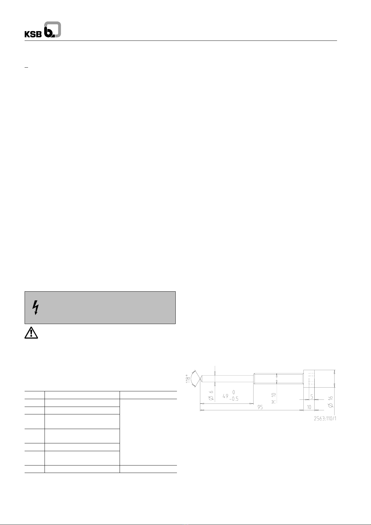
3. For dismantling the impeller, an M10 jacking thread is
provided at the impeller hub. Screw in the jack as shown in
the drawing below and remove the impeller.
Impeller removal kit: 39 022 760
4. Push mechanical seal 433.02 along the shaft.
5. Drain off the oil (see drawing below).