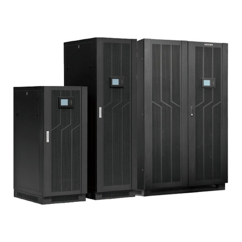
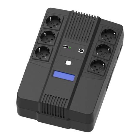
KStar UDC9101S One User manual

1
Allrightsreserved.
Theinformationinthisdocumentissubjecttochangewithoutnotice.
Publishstatement
ThankyouforpurchasingthisseriesUPS.
ThisseriesUPSisanintelligent,singlephaseinsinglephaseout,highfrequency
onlineUPSdesignedbyourR&Dteamwhoiswithyearsofdesigningexperienceson
UPS.Withexcellentelectricalperformance,perfectintelligentmonitoringand
networkfunctions,smartappearance,complyingwithEMCandsafetystandards,The
UPSmeetstheworld’sadvancedlevel.
Readthismanualcarefullybeforeinstallation
Thismanualprovidestechnicalsupporttotheoperatoroftheequipment.

2
TableofContents
1.ImportantSafetyWarning..................................................................................................................3
1-1Transportation ............................................................................................................................3
1-2Preparation...................................................................................................................................3
1-3Installation....................................................................................................................................3
1-4Operation......................................................................................................................................4
1-5Maintenance,serviceandfaults...........................................................................................4
1-6Symbolsusedinthisguide.....................................................................................................5
2.Installationandsetup...........................................................................................................................5
2-1Unpackchecking ........................................................................................................................5
2-2Realpanelview ...........................................................................................................................6
2-3SetuptheUPS..............................................................................................................................7
2-4UPSstartupandturnoff........................................................................................................9
3.Operations..............................................................................................................................................13
3-1Buttonoperation......................................................................................................................13
3-2LCDdisplay .................................................................................................................................13
3-3UPSsetting.................................................................................................................................15
3-4OperationalStatusandMode(s) ........................................................................................17
3-5AlarmorFaultreferencecode.............................................................................................18
4.Troubleshooting ...................................................................................................................................19
5.StorageandMaintenance.................................................................................................................21
6.Options ....................................................................................................................................................21
7.Specification ..........................................................................................................................................23

3
1. ImportantSafetyWarning
Importantsafetyinstructions–Savetheseinstructions
Pleasecomplywithallwarnings andoperatinginstructions inthismanual strictly.
Save this manual properly and read carefully the following instructions before
installing the unit. Do not operate this unit before reading through all safety
informationandoperatinginstructionscarefully
ThereexistsdangerousvoltageandhightemperatureinsidetheUPS.Duringthe
installation, operation andmaintenance, please abide the local safety instructions
andrelativelaws,otherwiseitwillresultinpersonnelinjuryorequipmentdamage.
Safetyinstructionsinthismanualactasasupplementaryforthelocalsafety
instructions. Our company will not assume the liability that caused by
disobeyingsafetyinstructions.
1-1 Transportation
PleasetransporttheUPSsystemonlyintheoriginalpackagetoprotectagainst
shockandimpact.
1-2 Preparation
CondensationmayoccuriftheUPSsystemismoveddirectlyfromcoldtowarm
environment.TheUPSsystemmustbeabsolutelydrybeforebeing installed.
PleaseallowatleasttwohoursfortheUPSsystemtoacclimatetheenvironment.
DonotinstalltheUPSsystemnearwaterorinmoistenvironments.
DonotinstalltheUPSsystemwhereitwouldbeexposedtodirectsunlightor
nearheater.
DonotblockventilationholesintheUPShousing.
1-3 Installation
DonotconnectappliancesordeviceswhichwouldoverloadtheUPSsystem(e.g.
laserprinters)totheUPSoutputsockets.
Placecablesinsuchawaythatnoonecansteponortripoverthem.
DonotconnectdomesticappliancessuchashairdryerstoUPSoutputsockets.
TheUPScanbeoperatedbyanyindividualswithnopreviousexperience.
ConnecttheUPSsystemonlytoanearthedshockproofoutletwhich must be
easilyaccessibleandclosetotheUPSsystem.
PleaseuseonlyVDE-tested,CE-markedmainscable(e.g.themainscableofyour
computer)toconnecttheUPSsystemtothebuildingwiringoutlet(shockproof
outlet).
PleaseuseonlyVDE-tested,CE-markedpowercablestoconnecttheloadstothe
UPSsystem.

4
When installing the equipment, it should ensure that the sum oftheleakage
currentoftheUPSandtheconnecteddevicesdoesnotexceed3.5mA.
1-4 Operation
DonotdisconnectthemainscableontheUPSsystemorthebuilding wiring
outlet(shockproofsocketoutlet)duringoperationssincethiswouldcancelthe
protectiveearthingoftheUPSsystemandofallconnectedloads.
The UPS system features its own, internal current source (batteries).TheUPS
outputsocketsoroutputterminalsblockmaybeelectricallyliveeveniftheUPS
systemisnotconnectedtothebuildingwiringoutlet.
InordertofullydisconnecttheUPSsystem,firstpresstheOFF/Enterbuttonto
disconnectthemains.
PreventnofluidsorotherforeignobjectsfrominsideoftheUPSsystem.
1-5 Maintenance,serviceandfaults
TheUPSsystemoperateswithhazardousvoltages.Repairsmaybecarriedout
onlybyqualifiedmaintenancepersonnel.
Caution - risk of electric shock. Even after the unit is disconnected from the
mains (building wiring outlet), components inside the UPS system are still
connectedtothebatteryandelectricallyliveanddangerous.
Before carrying out any kind of service and/or maintenance, disconnect the
batteriesandverifythatnocurrentispresentandnohazardousvoltageexistsin
theterminalsofhighcapabilitycapacitorsuchasBUS-capacitors.
Only persons are adequately familiar with batteries and with the required
precautionary measures may replace batteries and supervise operations.
Unauthorizedpersonsmustbekeptwellawayfromthebatteries.
Caution-riskofelectricshock.Thebatterycircuitisnotisolatedfromtheinput
voltage.Hazardousvoltagesmay occurbetweenthebatteryterminalsandthe
ground.Beforetouching,pleaseverifythatnovoltageispresent!
Batteriesmaycauseelectricshockandhaveahighshort-circuitcurrent.Please
take the precautionary measures specified below and any other measures
necessarywhenworkingwithbatteries:
-removewristwatches,ringsandothermetalobjects
-useonlytoolswithinsulatedgripsandhandles.
Whenchangingbatteries,installthesamenumberandsametypeofbatteries.
Donotattempttodisposeofbatteriesbyburningthem.Thiscouldcausebattery
explosion.
Donotopenordestroybatteries.Escapingelectrolytecancauseinjurytotheskin
andeyes.Itmaybetoxic.

5
Pleasereplacethefuseonlywiththesametypeandamperageinordertoavoid
firehazards.
DonotdismantletheUPSsystem.
1-6 Symbolsusedinthisguide
WARNING!
Riskofelectricshock
CAUTION!
Readthisinformationtoavoidequipmentdamage
2. Installationandsetup
NOTE:Beforeinstallation,pleaseinspecttheunit.Besurethatnothinginsidethe
packageisdamaged.Pleasekeeptheoriginalpackageinasafeplaceforfutureuse.
2-1 Unpackchecking
Don’tleantheUPSwhenmovingitoutfromthepackaging.
ChecktheappearancetoseeiftheUPSisdamagedornotduringthe
transportation,donotswitchontheUPSifanydamagefound.Pleasecontactthe
dealerrightaway.
Checktheaccessoriesaccordingtothepackinglistandcontactthedealerincase
ofmissingparts.
Itincludes:
(1) UPSuser'sguide
(2) SoftwareSuiteCD
(3) USBcable
(4) Powercord(Inputandoutput)
(5) RS232cable

6
2-2 Realpanelview
1KVA(S):
1KVA(H):
2KVA(S):
2KVA(H)/3KVA(H)

7
2KVA(S)-6batt /3KVA(S):
1. ACinput
2. Network/Fax/ModemSurgeProtection(option)
3. Inputcircuitbreaker
4. EPO(option)
5. USBcommunicationport(option)
6. RS-232communicationport
7. SNMPintelligentslot(option)
8. Outputreceptacles
9. BatteryTerminal
10. OutputTerminal
2-3 SetuptheUPS
Step 1: UPS input connection
Plug the UPS into a two-pole, three-wire, grounded receptacle only. Avoid using extension
cords.
For 200/208/220/230/240VAC models: The power cord is supplied in the UPS package.
Step 2: UPS output connection

8
For socket-type outputs, simply connect devices to the outlets.
For terminal-type input or outputs, please follow below steps for the wiring configuration:
a) Remove the small cover of the terminal block
b) Suggest using AWG14 or 2.1mm2power cords for 3KVA (200/208/220/230/240VAC
models).
c) Upon completion of the wiring configuration, please check whether the wires are
securely affixed.
d) Put the small cover back to the rear panel.
Step 3 Communication connection
Communication port:
To allow for unattended UPS shutdown/start-up and status monitoring, connect the
communication cable one end to the USB/RS-232 port and the other to the
communication port of your PC. With the monitoring software installed, you can
schedule UPS shutdown/start-up and monitor UPS status through PC.
The UPS is equipped with intelligent slot perfect for either SNMP or Relay card. When
installing either SNMP or Relay card in the UPS, it will provide advanced communication
and monitoring options.
NOTE: USB port and RS-232 port can’t work at the same time.
Step 4: Turn on the UPS
Press the ON button on the front panel for two seconds to power on the UPS.
Note: The battery charges fully during the first five hours of normal operation. Do not
expect full battery run capability during this initial charge period.
Step 5: Install software
For optimal computer system protection, install UPS monitoring software to fully
configure UPS shutdown. You may insert provided CD into CD-ROM to install the
monitoring software.
Step 6: External battery connection
If your UPS is not including batteries. Please connect external batteries as below chart.

9
2-4 UPSstartupandturnoff
Startupoperation
(1)TurnontheUPSinlinemode
NOTE Verify that the total equipment ratings do not exceed the UPS
capacitytopreventanoverloadalarm.
a) Oncemainspowerispluggedin,theUPSwillchargethebattery,atthemoment,
theLCDshowsthattheoutputvoltageis220,whichmeanstheUPSautomatically
tarttheinverter.Ifitisexpectedtochangetobypass model,youcanPress“OFF”
key.
b) PressandholdtheONkeyformorethanthreesecondstostarttheUPS,thenitwill
starttheinverter.
c) Oncestarted,theUPSwillperformaself-testfunction,LEDwilllightandgoout
circularly and orderly. When the self-test finishes, it will come to line mode, the
correspondingLEDlights,theUPSisworkinginlinemode.
(2)TurnontheUPSbyDCwithoutmainspower
a) Whenmainspowerisdisconnected,pressandholdtheONkeyformorethanhalfa
secondtostartUPS.
b) TheoperationoftheUPSintheprocessofstartisalmostthesameasthatwhen
mainspowerisin.Afterfinishingtheself-test,thecorrespondingLEDlightsandthe
UPSisworkinginbatterymode.
Turnoffoperation
(1) TurnofftheUPSinlinemode
a) PressandholdtheOFFkeyformorethanhalfasecondtoturnoff theUPS and
inverter.
b) AftertheUPSshutdown,theLEDsgooutandthereisnooutput. If output is
needed,youcansetbps“ON”ontheLCDsettingmenu.
(1) TurnofftheUPSbyDCwithoutmainspower
a) PressandholdtheOFFkeyformorethanhalfasecondtoturnofftheUPS.
b) WhenturningofftheUPS,itwilldoself-testingfirstly.TheLEDslightandgoout
circularlyandorderlyuntilthereisnodisplayonthecover.
Operation and Display Panel
Theoperationanddisplaypanel,showninbelowchart,isonthefrontpanelofthe
inverter.Itincludesthreeindicators,fourfunctionkeysandaLCDdisplay,indicatingthe
operatingstatusandinput/outputpowerinformation.

10
LCD control panel introduction
(1)LED(fromright toleft:“alarm”,“bypass”,“battery”,“inverter”);
(2)On-LineUPSLCDdisplay;(3)Functionkeys
LED Indicator
Indicator Description
Red
OnTheUPShasanactivealarmorfault.
Yellow
TheUPSisinBypassmode.
OnTheUPSisoperatingnormallyonbypass
duringHighEfficiencyoperation.
Yellow
OnTheUPSisinBatterymode.
Green
OnTheUPSisoperatingnormally.
NOTE
Whenpoweronorstartup,theseindicatorswillturnonandoffsequentially.
NOTE
Ondifferentoperationmodes,theseindicatorswillindicatedifferently.

11
Function Keys
FunctionKey Description
ESC/OFF ToexitsettingmodeOrturnofftheups
UP TogotopreviousselectionOrturnontheups
Down Togotonextselection
ENTER/ON Toconfirmtheselectioninsettingmodeorentersettingmode
LCD Display Icons
Icon
Function
description
InputSourceInformation
IndicatestheACinput.
Indicate input voltage, input frequency, PV voltage, battery
voltageandTemp
ConfigurationProgramandFaultInformation
Indicatesthesettingprograms.
Indicatesthewarningandfaultcodes.
Warning: flashingwithwarningcode.
Fault:lightingwithfaultcode

12
OutputInformation
Indicateoutputvoltage,outputfrequency,loadpercent,loadinVA,
loadin
Wattanddischargingcurrent.
BatteryInformation
Indicatesbatterylevelby0-24%,25-49%,50-74%and75-100%in
batterymodeandchargingstatusinlinemode.
InACmode,itwillpresentbatterychargingstatus.
Status Batterycapacity LCDDisplay
Constant
Currenmode
0-24% 4barswillflashinturns
25-49% Bottom bar will be on and the other three
barswillflashinturns
50-74% Bottomtwobarwillbeonandtheothertwo
barswillflashinturns
75-100% Bottomthreebarwillbeonandthetopbars
willflash
LoadInformation
Indicatesoverload.
Indicatestheloadlevelby0-24%,25-50%,50-74%and75-100%.
0%~25% 25%~50% 50%~75% 75%~100%
ModeOperationInformation
Indicatesunitconnectstothemains.
Indicatesloadissuppliedbyutilitypower.
Indicatestheutilitychargercircuitisworking.
IndicatestheDC/ACinvertercircuitisworking.
MuteOperation
Indicatesunitalarmisdisabled.

13
3. Operations
3-1 Buttonoperation
3-2 LCDdisplay
Partone:Rackdisplay
Thereare9interfacesavailableintheLCDdisplay.
ButtonFunction
ON /ENTER Button
TurnontheUPS:PressandholdONbuttonfor
atleast2secondstoturnontheUPS.
Confirmcurrentsettings:WhentheUPSenters
thesettingmode,mustpressthisbuttonto
confirmthesettingsvaluewhatyouwant,nest
pressup/downbuttontochangesettings
information
Outoffbypassmode:whentheUPSenterto
bypassmode,pressandholdthisbuttonitwill
switchtonormalmode.
OFF /ESC Button
TurnofftheUPS:Pressandholdthisbuttonat
least2secondstoturnofftheUPSinbattery
mode.UPSwillbeinstandbymodeunder
powernormalortransfertoBypassmodeifthe
Bypassenablesettingbypressingthisbutton.
Exitsettingmode:Pressthisbuttontoconfirm
selectionandexitsettingmodewhenLCD
displaythelastselectioninUPSsettingmode.
UP ButtonUpkey:Pressthisbuttontodisplayprevious
selectioninUPSsettingmode.
DOWN Button Downkey:Pressthisbuttontodisplaynext
selectioninUPSsettingmode.
UP + DOWN Button Settingmode:Pressandholdthisbuttonfor5
secondstoenterUPSsettingmode.

14
Item InterfaceDescription ContentDisplayed
01 Inputvoltage&Output
voltage
02 Batteryvoltage&Battery
capacity
03 Inputfrequency&
Outputfrequency
04 Load
05 Environment
Temperature

15
06 UPSmodel.
07 FirmwareVersion
08
AlarmCode(Warming
Message)
Allalarmcodesare
presentwhenabnormal
behavior(s)occur(s)
3-3 UPSsetting
TheUPShassettingfunctions.ThisusersettingscanbedoneunderanykindofUPS
workingmode.Thesettingwilltakeeffectundercertaincondition.Belowtable
describeshowtosettheUPS.
Thesettingfunctioniscontrolledby4buttons(Up,Down,ON/Enter,OFF/ESC):
Up▲+OFF/Down▼---goesintothesettingpage,
ON/Enter--- -confirmthe settingsoptions
Up▲&Down▼---valueadjustmentOrforchoosingdifferentpages.
AftertheUPSturnON,pressbuttons “▲&▼” for5secondsandthengoesintothe
settinginterfacepage.

16
Item Settings Contentdisplay
01
Modesetting
PressEnterbuttontochangethe
setting(ECOorNORorCF).
PressUP▲button toselectthe
previoussetting.
PressDOWN▼button toselect
thenextsetting.
02
Outputvoltagesetting
PressEnterbuttontochangethe
setting(200,208,220,230,240).
PressUP▲button toselectthe
previoussetting.
PressDOWN▼button toselect
thenextsetting.
03
Frequencysetting
PressEnterbutton tochange
thesetting(50or60Hz).
PressUPbutton▲ toselectthe
previoussetting.
PressDOWNbutton▼toselect
thenextsetting.
04
Batterycapacitysetting
PressEnterbutton tochange
thesetting(Batterycapacity
rangeis1-200Ah).
PressUPbutton▲toselectthe
previoussetting.
PressDOWNbutton▼toselect
thenextsetting.
05
BatteryEODvoltaesetting
PressEnterbutton tochange
thesetting(1.60/1.70/1.75/1.80).
PressUPbutton▲toselectthe
previoussetting.
PressDOWNbutton▼toselect
thenextsetting.

17
06
Bypassvoltageupperlimitsetting
PressEnterbutton tochange
thesetting(Thebypassvoltage
upperlimitrangeis230-264Vac).
PressUPbutton▲toselectthe
previoussetting.
PressDOWNbutton▼toselect
thenextsetting.
07
Bypassvoltagelowerlimitsetting
PressEnterbuttontochangethe
setting(Thebypassvoltagelower
limitrangeis170-220Vac).
PressUPbutton toselectthe
previoussetting.
PressDOWNbutton toselect
thenextsetting.
08
Mutesetting
PressEnterbuttontochangethe
setting(ONorOFF).
PressUPbutton toselectthe
previoussetting.
PressDOWNbutton tosaveand
exitthesetup.
09
BYPASSenable/disablesetting
PressEnterbuttontochangethe
setting(ONorOFF).
PressUPbutton▲toselectthe
previoussetting.
PressDOWNbutton▼tosave
andexitthesetup.
3-4 OperationalStatusandMode(s)
item ContentDisplayed
1 Initialized
2 StandbyMode
3 NoOutput
4 BypassMode

18
5 UtilityMode
6 BatteryMode
7 BatterySelf-diagnostics
8 Inverterisstartingup
9 ECOMode
10 EPOMode
11 MaintenanceBypassMode
12 FaultMode
3-5 AlarmorFaultreferencecode
Eventlog UPSAlarmWarning Buzzer LED
1 RectifierFault Beepcontinuously FaultLEDlit
2 Inverterfault(IncludingInverter
brid
g
eisshorted) Beepcontinuously FaultLEDlit
9 Fanfault Beepcontinuously FaultLEDlit
12 Selftestfault Beepcontinuously FaultLEDlit
13 BatteryChargerfault Beepcontinuously FaultLEDlit
15 DCBusovervoltage Beepcontinuously FaultLEDlit
16 DCBusbelowvoltage Beepcontinuously FaultLEDlit
17 DCbusunbalance Beepcontinuously FaultLEDlit
18 Softstartfailed Beepcontinuously FaultLEDlit
19 UPSInsideOverTemperature Twicepersecond FaultLEDlit
20 HeatsinkOverTemperature Twicepersecond FaultLEDlit
26 Batteryovervoltage Oncepersecond FaultLEDblinking
29 OutputShort-circuit Oncepersecond FaultLEDblinking
30 Inputcurrentlimit Oncepersecond FaultLEDblinking
31 Bypassovercurrent Oncepersecond BPSLEDblinking
32 Overload Oncepersecond INVorBPSLED
blinkin
g
33 Nobattery Oncepersecond BatteryLEDblinking
34 Batteryundervoltage Oncepersecond BatteryLEDblinking
35 Batterylowpre-warning Oncepersecond BatteryLEDblinking
36 Overloadtimeout Onceper2seconds FaultLEDblinking
37 DCcomponentoverlimit. Onceper2seconds INVLEDblinking
39 Mainsvolt.Abnormal Onceper2seconds BatteryLEDlit
40 Mainsfreq.abnormal Onceper2seconds BatteryLEDlit
41 BypassNotAvailable BPSLEDblinking

19
4. Troubleshooting
IftheUPSsystemdoesnotoperatecorrectly,pleasesolvetheproblembyusingthe
tablebelowandtheTroubleShootingChart.
SymptomPossiblecauseRemedy
Noindicationandalarmeven
thoughthemainsisnormal.
TheACinputpoweris
notconnectedwell.
Checkifinputpowercord
firmlyconnectedtothe
mains.
TheACinputis
connectedtotheUPS
output.
PlugACinputpowercord
toACinputcorrectly.
Alarmcodeisshownas“33”
andbatteryledblinking.
Theexternalor
internalbatteryis
incorrectlyconnected.
Checkifallbatteriesare
connectedwell.
Alarmcodeisshownas“26”
andbatteryledblinking.
Batteryvoltageistoo
highorthechargeris
fault.
Contactyourdealer.
Alarmcodeisshownas“34”
andbatteryledblinking
Batteryvoltageistoo
loworthechargeris
fault.
Contactyourdealer.
Alarmcodeisshownas“32”
andINVorBYPASSled
blinking.
UPSisoverload
Removeexcessloadsfrom
UPSoutput.
Alarmcodeisshownas“29”
andFAULTledlight.
TheUPSshutdown
automaticallybecause
shortcircuitoccurson
theUPSoutput.
Checkoutputwiringandif
connecteddevicesarein
shortcircuitstatus.
Alarmcodeisshownas“9”
andFAULTledlight. Fanfault. Contactyourdealer.
Alarmcodeisshownas
“01,02,15,16,17,18”
AUPSinternalfault
hasoccurred. Contactyourdealer.
Batterybackuptimeisshorter
thannominalvalue
Batteriesarenotfully
charged
Chargethebatteriesforat
least5hoursandthen
checkcapacity.Ifthe
problemstillpersists,
consultyourdealer.
Batteriesdefect Contactyourdealerto
replacethebattery.

20
TroubleShootingChart
This manual suits for next models
5
Table of contents
Other KStar UPS manuals

KStar
KStar HIP3300E User manual

KStar
KStar YDC9300-RT Series User manual

KStar
KStar 6K-H User manual

KStar
KStar 1K User manual

KStar
KStar YDC9300-RT Series User manual

KStar
KStar HPM3340 200k User manual

KStar
KStar YMK3300 Series User manual

KStar
KStar YMK3300-200k User manual

KStar
KStar YDC9300-B User manual

KStar
KStar UDC9100 Series User manual
Popular UPS manuals by other brands

Compaq
Compaq Pro UPS 500 Operation and reference guide

Avaya
Avaya RS9 Installation and operator's manual

HP
HP HP T1000J Quick start card

Xtreme Power Conversion
Xtreme Power Conversion P91g Series User & installation manual

Falcon
Falcon ED1000RM-1 Owner's operating manual

Delta Electronics
Delta Electronics E series user manual