KStar HIP3300E User manual

All rights reserved.
The information in this document is subject to change without notice.
Publish statement
Thank you for purchasing this series UPS.
This series UPS is an intelligent, three phase in Three phase out, high frequency online
UPS designed by our R&D team who is with years of designing experiences on UPS.
With excellent electrical performance, perfect intelligent monitoring and network
functions, smart appearance, complying with EMC and safety standards, The UPS
meets the world’s advanced level.
Read this manual carefully before installation
This manual provides technical support to the operator of the equipment.

1
Contents
1.Safety ....................................................................................................................................... 2
1.1 Safety notes ....................................................................................................................................... 2
1.2 Symbols used in this guide ............................................................................................................ 2
2.Main Features ........................................................................................................................ 3
2.1 Summarization ................................................................................................................................... 3
2.2 Functions and Features .................................................................................................................. 3
3.Installation .............................................................................................................................. 4
3.1 Unpack checking .............................................................................................................................. 4
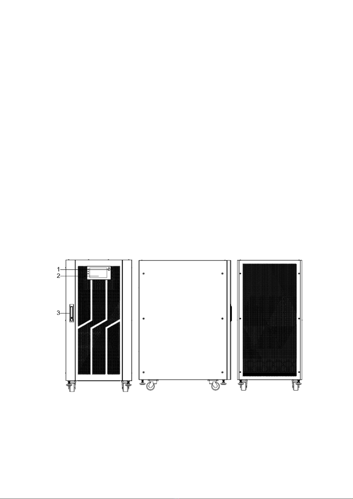
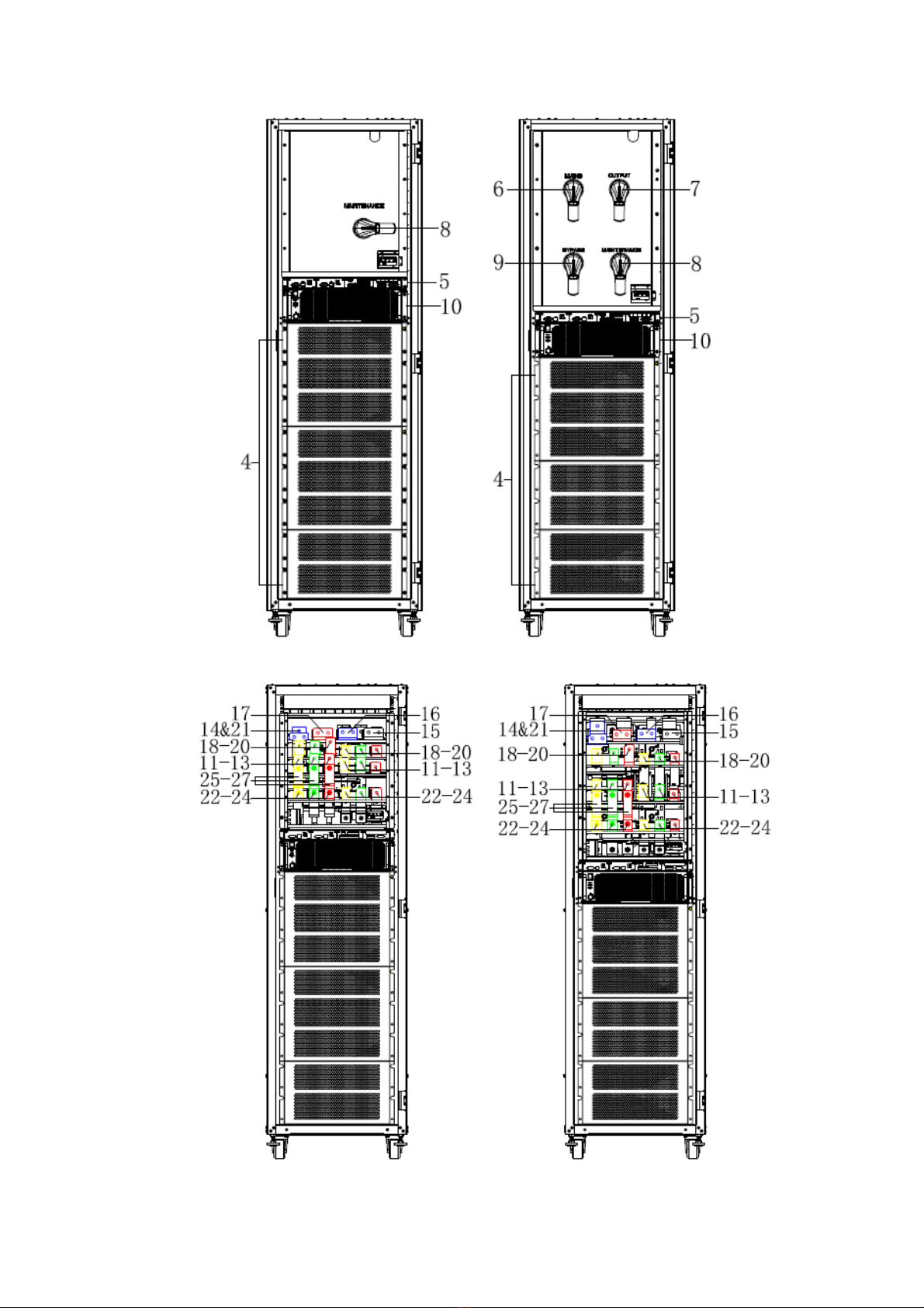
3.2 The appearance of the product ..................................................................................................... 4
3.3 Installation notes ............................................................................................................................ 15
3.4 External Protective Devices .......................................................................................................... 18
3.5 Power Cables ................................................................................................................................... 19
3.6 Power cable connect...................................................................................................................... 23
3.7 Battery connection ......................................................................................................................... 24
3.8 UPS parallel Installation ................................................................................................................ 25
3.8.1 Cabinet installation ............................................................................................................. 26
3.8.2 Parallel cable installation .................................................................................................. 26
3.9 LBS installation (optional) ............................................................................................................ 27
3.9.1 LCD setting ........................................................................................................................... 27
3.9.2 LBS cable installation ......................................................................................................... 27
3.9.3 UPS installation .................................................................................................................... 28
4.Operation .............................................................................................................................. 28
4.1 Operation Modes ............................................................................................................................. 28
4.2 Turn on/off UPS ............................................................................................................................... 31
4.2.1 Restart procedure ................................................................................................................ 31
4.2.2 Test procedure ..................................................................................................................... 31
4.2.3 Cold start procedure ........................................................................................................... 32
4.2.4 MAINTENANCE BYPASS ................................................................................................... 32
4.2.5 Shut down procedure ......................................................................................................... 33
4.2.6 Startup procedure for parallel system ........................................................................... 33
4.3 The Display ....................................................................................................................................... 34
4.4 Display Messages/Troubleshooting ........................................................................................... 64
4.5 Options .............................................................................................................................................. 66
Appendix 1 Specifications ..................................................................................................... 67
Appendix 2 Problems and Solution ..................................................................................... 72
Appendix 3 CAN communication port definition ............................................................. 74
Appendix 4 RS485 communication port definition ......................................................... 75
Appendix 5 COM communication port definition ............................................................ 75
Appendix 6 LBS port definition ............................................................................................ 76
Appendix 7 REPO instruction ............................................................................................... 76

2
1.Safety
Important safety instructions – Save these instructions
There exists dangerous voltage and high temperature inside the UPS. During the
installation, operation and maintenance, please abide the local safety instructions and relative
laws, otherwise it will result in personnel injury or equipment damage. Safety instructions in this
manual act as a supplementary for the local safety instructions. Our company will not assume the
liability that caused by disobeying safety instructions.
1.1 Safety notes
1. Even no connection with utility power, 220/230/240VAC voltage may still exist at UPS outlet!
2. For the sake of human being safety, please well earth the UPS before starting it.
3.Don’t open or damage battery, for the liquid spilled from the battery is strongly poisonous and
do harmful to body!
4.Please avoid short circuit between anode and cathode of battery, otherwise, it will cause
spark or fire!
5.Don’t disassemble the UPS cover, or there may be an electric shock!
6.Check if there exists high voltage before touching the battery
7.Working environment and storage way will affect the lifetime and reliability of the UPS. Avoid
the UPS from working under following environment for long time
◆ Area where the humidity and temperature is out of the specified range (temperature 0
to 40℃, relative humidity 5%-95%)
◆ Direct sunlight or location nearby heat
◆ Vibration Area with possibility to get the UPS crashed.
◆ Area with erosive gas, flammable gas, excessive dust, etc
8.Keep ventilations in good conditions otherwise the components inside the UPS will be
over-heated which may affect the life of the UPS.
1.2 Symbols used in this guide
WARNING!
Risk of electric shock

3
CAUTION!
Read this information to avoid equipment damage
2.Main Features
2.1 Summarization
This series UPS is a kind of three-in-three-out high frequency online UPS, it provides seven
specifications: The 100~1200kVA. The UPS can solve most of the power supply problems, such
as blackout, over-voltage, under-voltage, voltage sudden drop, oscillating of decreasing extent,
high voltage pulse, voltage fluctuation, surge, inrush current, harmonic distortion (THD), noise
interference, frequency fluctuation, etc..
This UPS can be applied to different applications from computer device, automatic equipment,
communication system to industry equipment.
2.2 Functions and Features
◆3Phase In/3Phase Out UPS
It is 3Phase In/3Phase Out high-density UPS system, of which input current is kept in balance.
No unbalance problem might occur.
◆Digital Control
This series UPS is controlled by Digital Signal Processor (DSP); enhance, it increases
reliability, performance, self-protection, and self-diagnostics and so on.
◆Battery Configurable from 30 blocks to 50 blocks
The battery voltage of this series UPS can be configured at 30 blocks, 32 blocks, 34 blocks, 36
blocks, 38 blocks, 40 blocks, 42 blocks, 44 blocks, 46 blocks, 48 blocks or 50 blocks according
to your convenience.
◆Charging Current is configurable
The user may set the capacity of the batteries as well as reasonable charging current.
Constant voltage mode, constant current mode or floating mode can be switched automatically
and smoothly.
◆Intelligent charging Method
The series UPS adopts advanced three-stage charging method—
1st stage: high current constant current charging
To guarantee to charge back to 90%;
2nd-stage: Constant Voltage
In order to vitalize battery and make sure batteries are fully charged
3rd stage: floating mode.
With this 3-stage charging method, it extends the life of the batteries and guarantees fast
charging.
◆Intelligent Monitoring Function
Via optional SNMP Card, you may remotely control and monitor the UPS.
◆Touch-screen Super-large LCD display

4
◆Equip with Maintenance Bypass Switch for easy maintenance purpose.
◆Superior MTTR (Meantime to repair) & Short shutdown time in maintenance
◆Centralized monitoring module is also available
◆EPO and REPO function
3.Installation
3.1 Unpack checking
1. Don’t lean the UPS when moving it out from the packaging
2. Check the appearance to see if the UPS is damaged or not during the transportation, do
not switch on the UPS if any damage found. Please contact the dealer right away.
3. Check the accessories according to the packing list and contact the dealer in case of
missing parts.
3.2 The appearance of the product
* Standard configuration : cabinet only with maintenance bypass switch
* Full configuration : cabinet with mains, bypass, maintenance and output switch
100kVA&120kVA&150K&160kVA(Full configuration), bottom entry
Front View Side View Rear View

5
Front View (internal) Front View (Copper bar)
200kVA & 250kVA & 300kVA (Full configuration) , bottom entry
Front View Side View Rear View

6
Front View (internal) Front View (Copper bar)
400kVA (Standard and Full configuration) , top or bottom entry
Front View Side View Rear View

7
400kVA(Standard and Full configuration) , top entry
Standard configuration Full configuration
Connect copper bar

8
400kVA(Standard and Full configuration) , bottom entry
Standard configuration Full configuration
Connect copper bar

9
400/500/600kVA(Standard and Full configuration), top and bottom entry
Front View Side View Rear View
400kVA(Standard and Full configuration) , top and bottom entry
Standard configuration Full configuration

10
Connect coppper bar Mains-bypass common copper bar
500kVA(Standard and Full configuration) , top and bottom entry
Standard configuration Full configuration

11
Connect coppper bar Mains-bypass common copper bar
600kVA(Standard and Full configuration) , top and bottom entry
Standard configuration Full configuration

12
Connect coppper bar Mains-bypass common copper bar
800/1000/1200kVA(Full configuration), top and bottom entry
Front View

13
Side View Rear View
Full configuration

14
Connect coppper bar
Mains-bypass common copper bar

15
(1) EPO key
(2) LCD panel : Display UPS data and status
(3) Front door lock
(4) Dustproof net plate
(5) Control unit
(6) Mains switch
(7) Output switch
(8) Maintenance switch
(9) Bypass switch
(10) Bypass module
(11) Mains-A input copper bar
(12) Mains-B input copper bar
(13) Mains-C input copper bar
(14) Input neutral copper bar
(15) Battery negative copper bar
(16) Battery neutral copper bar
(17) Battery positive copper bar
(18) Output-A input copper bar
(19) Output-B input copper bar
(20) Output-C input copper bar
(21) Output neutral copper bar
(22) Bypass-A input copper bar : Wiring must be used when mains-bypass separation
(23) Bypass-B input copper bar : Wiring must be used when mains-bypass separation
(24) Bypass-C input copper bar : Wiring must be used when mains-bypass separation
(25) Phase A mains-bypass common input connect copper bar
(26) Phase B mains-bypass common input connect copper bar
(27) Phase C mains-bypass common input connect copper bar
Control unit

16
(1) ECU1/2 : Centralized control unit
(2) Dry-contact unit
(3) monitor unit
(4) Intelligent slot
ECU unit
(1) PARALLEL port
(2) LBS port
(3) LED
Dry-contact unit
(1) EPO port : NO-12V : normaly open port; NC-12V : normaly close port;
(2) SWITCH STATUS : OUT-0V : output breaker auxiliary contact singnal port; MT-0V :
maintenance breaker auxiliary contact singnal port; BP-0V : bypass breaker auxiliary contact
singnal port; BAT-0V : battery breaker auxiliary contact singnal port;
(3) The other port : BTG-0V : battery grounding detect singnal input port; DRV-0V : battery
breaker driver singnal output port; SPD-0V : SPD detect singnal input port; GEN-0V :
generator detect singnal input port;
(4) BP_FEEDBACK : PIN1_NC, PIN2_NO,PIN4_common
(5) Optional dry contacts : 6 ports, can optional by LCD.
Monitor unit

17
(1) BAT_T : NTC temperature sensor port
(2) R-CAN : CAN communication resistor adjust
(3) USB port : for software updata and history download
(4) RS232 port : for communication
(5) LCD port
(6) CAN port : BMS port
(7) FE : Net port (reserve)
(8) RS485 port: for communication
(9) RS485 port: for communication
(10) BAT_T : battery temperature sensor port (RS485)
3.3 Installation notes
Note: Consider for the convenience of operation and maintenance, the space in front and
back of the cabinet should be left at least 800mm and 800mm respectively when installing the
cabinet.
◆Please place the UPS in a clean, stable environment, avoid the vibration, dust, humidity,
flammable gas and liquid, corrosive. To avoid from high room temperature, a system of room
extractor fans is recommended to be installed. Optional air filters are available if the UPS operates
in a dusty environment.

18
◆The environment temperature around UPS should keep in a range of 0℃~40 . If ℃the
environment temperature exceeds 40 , the rated load capacity should ℃be reduced by 12% per
5 . The max temperature can't be higher than 50 .℃℃
◆If the UPS is dismantled under low temperature, it might be in a condensing condition. The
UPS can't be installed unless the internal and external of the equipment is fully dry. Otherwise,
there will be in danger of electric shock.
◆Batteries should be mounted in an environment where the temperature is within the required
specs. Temperature is a major factor in determining battery life and capacity. In a normal
installation, the battery temperature is maintained between 15°C and 25°C. Keep batteries away
from heat sources or main air ventilation area, etc.
WARNING!
Typical battery performance data are quoted for an operating temperature between
20°C and 25°C. Operating it above this range will reduce the battery life while
operation below this range will reduce the battery capacity.
◆Should the equipment not be installed immediately it must be stored in a room so as to
protect it against excessive humidity and or heat sources.
CAUTION!
An unused battery must be recharged every 6months temporarily connecting the
UPS to a suitable AC supply mains and activating it for the time required for
recharging the batteries.
◆The highest altitude that UPS may work normally with full load is 1500 meters. The load
capacity should be reduced when this UPS is installed in place whose altitude is higher than 1500
meters, shown as the following table:
(Load coefficient equals max load in high altitude place divided by nominal power of the UPS)
Altitude(m) 1500 2000 2500 3000 3500 4000 4500 5000
Load coefficient 100% 95% 90% 85% 80% 75% 70% 65%
◆The UPS cooling is depending on fan, so it should be kept in good air ventilation area.
There are many ventilation holes on the front and rear, so they should not be blocked by any exotic
obstacles.
3.4 External Protective Devices
For safety reasons, it is necessary to install, external circuit breaker at the input A.C. supply
and the battery. This chapter provides guidelines for qualified installers that must have the
knowledge of local wiring practices for the equipment to be installed.
◆External Battery
The UPS and its associated batteries are protected against the effect of over-current
through a DC compatible thermo-magnetic circuit-breaker (or a set of fuses) located
close to the battery.
◆UPS Output
Any external distribution board used for load distribution shall be fitted with protective
devices that may avoid the risk of UPS overloaded.
◆Over-current
Protection device shall be installed at the distribution panel of the incoming main
supply. It may identify the power cables current capacity as well as the overload capacity

19
of the system.
3.5 Power Cables
◆The cable design shall comply with the voltages and currents provided in this section, Kindly
follow local wiring practices and take into consideration the environmental conditions
(temperature and physical support media).
WARNING!
UPON STARTING, PLEASE ENSURE THAT YOU ARE AWARE OF THE
LOCATION AND OPERATION OF THE EXTERNAL ISOLATORS WHICH ARE
CONNECTED TO THE UPS INPUT/BYPASS SUPPLY OF THE MAINS
DISTRIBUTION PANEL.CHECK TO SEE IF THESE SUPPLIES ARE
ELECTRICALLY ISOLATED, AND POST ANY NECESSARY WARNING SIGNS TO
PREVENT ANY INADVERTENT OPERATION
3.6.1 Recommended cross-sectional areas for power cables
◆For future expansion purpose, it is economical to install power cable according to the full rating
capacity initially. The diameter of cable is shown bellow:
UPS
cabinet
Cable Dimension
AC Input
(mm2)
BPS Input
(mm2)
AC Output
(mm2)
DC Input
(mm2)
Grounding
(mm2)
100
70 50 120 35 25
120
95 70 150 50 35
150
120 120 120 150 50
160
120 120 120 150 50
200
185 150 150 240 70
250
240 185 185 120*2 95
300
120*2 120*2 120*2 150*2 120
400
185*2 150*2 150*2 240*2 150
500
150*3 240*2 240*2 185*3 240
600
240*3 150*3 150*3 240*3 150*2
800
240*3 185*3 185*3 240*4 240*2
1000
240*4 240*4 240*4 185*6 240*3
1200
240*5 240*4 240*4 240*6 240*4
◆ When selecting, connecting, and routing power cables, follow local safety regulations and rules.
◆ If external conditions such as cable layout or ambient temperatures change, perform
verification in accordance with the IEC-60364-5-52 or local regulations.
◆ If the rated voltage is 400 V, multiply the currents by 0.95. If the rated voltage is 415 V,
multiply the currents by 0.92.
◆ If primary loads are non-linear loads, increase the cross-sectional areas of neutral
wires1.5–1.7 times.
◆ The nominal battery discharge current refers to the current of forty 12 V batteries at 480V
in standard configuration.
◆ The maximum battery discharge current refers to the current when forty 12 V batteries in
standard configuration, that is, two hundred and forty 2 V battery cells (1.67 V/cell), stop
discharging.
◆ The battery cable specifications are selected based on 40 batteries by default and
compatible with application scenarios with 30–40 batteries.
◆ When the mains input and bypass input share a power source, configure both types of input
power cables as mains input power cables. The cables listed in Table are used only when
Table of contents
Other KStar UPS manuals

KStar
KStar 6kVA User manual

KStar
KStar UDC9100 Series User manual

KStar
KStar YDC9300-RT Series Quick start guide

KStar
KStar YDC9300-0.8 User manual

KStar
KStar UDC9101RTS User manual

KStar
KStar YMK3300-200k User manual

KStar
KStar 600 User manual

KStar
KStar YDC9300-RT Series User manual

KStar
KStar 6K-H User manual

KStar
KStar HPM3340 200k User manual