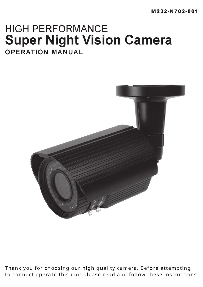
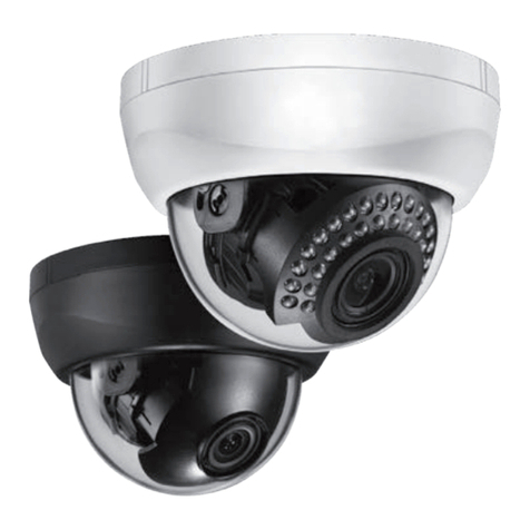
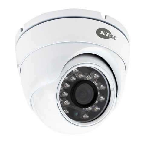
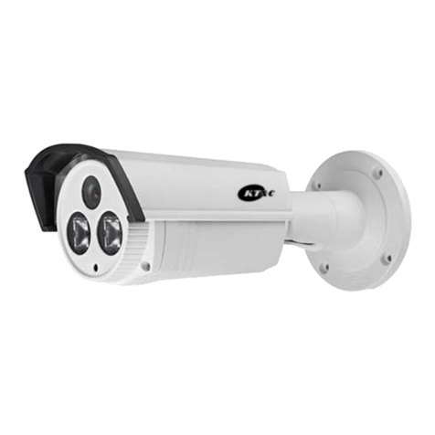
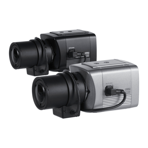
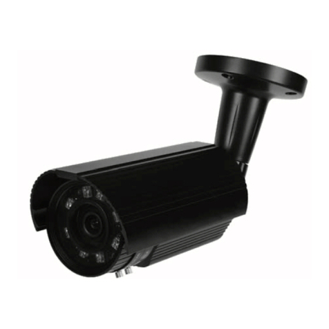
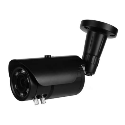
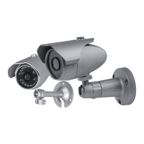
KT&C KPC-N571U User manual

HIGH PERFORMANCE
Super Night Vision Camera
OPERATION MANUAL
Thank you for choosing our high quality camera.
Before attempting to connect or operate, please read and follow
these instructions.
M165-N571U-002

CONTENTS
1. CAUTIONS
2. IMPORTANT SAFETY INSTRUCTION
3. COMPONENTS
4. NAME AND FUNCTION
5. INSTALLATION
6. DIMENSIONS
7. SPECIFICATION
8. OSD MANUAL
2

1. CAUTIONS
3
This device complies with Part 15 of the FCC
Rules. Operation is subject to the following two
conditions;
1. This device may not cause harmful interference.
2. This device must accept any interference received, including
interference that may cause undesired operation.
1. A regulated DC12V 3A power supply is recommended for use with this camera
for the best picture and the most stable operation.
An unregulated power supply can cause damage to the camera.
When unregulated power supply is applied, product warranty will be
out of subject.
2. It is recommended that the camera is used with a monitor that has a CCTV quality
75 video impedance level.
If your monitor is switched to high impedance then please adjust accordingly.
3. Do not attempt to disassemble the camera to gain access to the internal componets.
Refer servicing to your dealer.
4. Never face the camera towards the sun or any bright or reective light, which may
cause smear on the picture and possible damage to the CCD.
5. Do not remove the serial sticker for the warranty service.
This equipment has been tested and found to comply with the limits for a Class A digital
device, pursuant to part 15 of the FCC Rules. These limits are designed to provide
reasonable protection against harmful interference when the equipment is operated
in a commercial environment. This equipment generates, uses, and can radiate radio
frequency energy and, if not installed and used in accordance with the instruction
manual, may cause harmful interference to radio communications. Operation of this
equipment in a residential area is likely to cause harmful interference in which case the
user will be required to correct the interference at his own expense.”
Note-
Any changes or modifications in construction of this device
which are not expressly approved by the party responsible
for compliance could void the user’s authority to operate the
equipment.
Caution -
This is a class A product. In a domestic environment this product
may cause radio interference in which case the user may be
required to take adequate measures.
WARNING -
1. CAUTIONS
4
Correct Disposal of This Product
(Waste Electrical & Electronic Equipment)
(Applicable in the European Union and other European countries with
separate collection systems)
This marking shown on the product or its literature, indicate that it should not
be disposed with other household wastes at the end of its working life. To
prevent possible harm to the environment or human health from uncontrolled
waste disposal, please separate this from other types of wastes and recycle it
responsibly to promote the sustainable reuse of material resources.
This product should not be mixed with other commercial wastes purchased this
product, or their local government ofce, for details of where and how they can
take item for environmentally safe recycling.
Business users should contact their supplier and check the terms and
conditions of the purchase contract.
Household users should contact either the retailer where they for disposal.

2. IMPORTANT SAFETY INSTRUCTION
1) Read these instructions.
2) Keep these instructions.
3) Heed all warnings.
4) Follow all instructions.
5) Do not use this apparatus near water.
6) Clean only with dry cloth.
7) Do not block any ventilation openings. Install in accordance
with the manufacturer’s instructions.
8) Do not install near any heat sources such as radiators, heat registers,
stoves, or other apparatus (including ampliers) that produce heat.
9) Do not defeat the safety purpose of the polarized or grounding-type plug. A
polarized plug has two blades with one wider than the other. A grounding type plug
has two blades and a third grounding prong. The wide blade or the third prong are
provided for your safety. If the provided plug does not t into your outlet, consult an
electrician for replacement of the obsolete outlet.
10) Protect the power cord from being walked on or pinched particularly at plugs,
convenience receptacles, and the point where they exit from the apparatus.
11) Only use attachments/accessories specied by the manufacturer.
12) Use only with the cart, stand, tripod, bracket, or table specied by the
manufacturer, or sold with the apparatus. When a cart is used,
use caution when moving the cart/apparatus combination to
avoid injury from tip-over.
13) Unplug this apparatus during lightning storms or when unused for long
periods of time.
14) Refer all servicing to qualied service personnel. Servicing is required when
the apparatus has been damaged in any way, such as power-supply cord or plug
is damaged, liquid has been spilled or objects have fallen into the apparatus, the
apparatus has been exposed to rain or moisture, does not operate normally, or has
been dropped.

3. COMPONENTS
SUPER NIGHT VISION
CAMERA
SUNSHIELD
VIDEO OUTPUT
TEST CABLE
L-WRENCH -2ea /
SCREW(5x30L) - 3ea /
SUNSHIELD FIXING BOLT
OPERATION MANUAL
6

4. NAME AND FUNCTION
7
① Sunshield Fixing Bolt
② Sunshield
③ Mounting Bracket
④ IR Illuminator
LED : Left(35ea), Right(35ea)
⑤ Photo cell
⑥ Body
⑦ Body Fixing Ring
⑧ External Zoom and
Focus adjustment
①
⑧ ④④ ④
③
⑥
③ ②
Back
Cable Concealed Thru Bracket
⑦⑤
External Zoom and Focus adjustment
After adjusting zoom and focus, to prevent
water inltration, rmly tighten the zoom and
focus lever.
Lens: f2.8 ~ 12.0 / F1.2 Lens: f5.0 ~ 50.0 / F1.4

5. INSTALLATION
• MOUNTING POSITION
360°
90°
15°
* 1st Axis * 2nd Axis
8
* 3rd Axis
360°

5. INSTALLATION
• MONITOR CONNECTION
(1) DC12V
(2) DUAL(DC12V/AC24V)
9
When you install the camera, please glue up the end of cable to
keep it stable in order to protect the camera from the humidity problems.
DC12V/AC24V
DC 12V POWER SUPPLY or
AC 24V POWER SUPPLY
VIDEO IN MONITOR
DC12V
BNC FEMALE
DC 12V POWER SUPPLY
VIDEO IN MONITOR

6. DIMENSIONS
10
87
88.6
107.8
Ø60
175.7
145
129.4
265.9
135
130
Ø80
M12XP1.25

7. SPECIFICATION
11
Signal Format NTSC PAL
Image Sensor 1/3” 960H SONY EXview HAD CCD II
Scanning System 2 : 1 Interlace
H Resolution. 750TV Lines
Scanning Frequency 15.734KHz(H), 59.94Hz(V) 15.625KHz(H), 50Hz(V)
Total Pixels No. 1020(H) X 508(V) 1020(H) X 596(V)
Effective Pixels No. 976(H) X 494(V) 976(H) X 582(V)
Electronic Shutter 1/60 sec 1/50 sec
S/N Ratio More than 50dB(AGC OFF)
Min. Illumination 0Lux (IR LED On)
Sync System Internal
Gamma r= 0.45
Video Output 1.0 Vp-p Composite (75Ω)
OSD Built in (Inner Key / Joystick)
BLC OFF / BLC / HLC
White Balance ATW / PUSH / USER1 / USER2 / ANTI CR / MANUAL / PUSH-LOCK
2DNR OFF / ON (Level adjustable)
ATR OFF / ON (Level adjustable)
Function MIRROR / BRIGHTNESS / CONTRAST / SHARPNESS / HUE / GAIN
Privacy Masking 8 zones with 8 selectable colours or mosaic (4 when Motion on)
Motion Detection 4 Zones
Day & Night Ture Day & Night with ICR Mechanism
Lens Aspheric Vari-focal DC IRIS Lens
Language ENGLISH / JAPANESE / GERMAN / FRENCH / RUSSIAN /
PORTUGUESE / SPANISH / CHINESE
IP Rating IP66 (Weather proof)
IR LED 70 EA (850nm)
IR LED Distance Up to 50M
Operating Temperature -40°C ~ 60°C (-40°F ~ 140°F)
Storage Temperature -20°C ~ 60°C (-4°F ~ 140°F)
Humidity Less than 80%
Power
Consumption
DC12V DC12V (±10%), Max 860mA
DUAL AC24V (±10%), Max 11W /
DC12V (±10%), Max 930mA
Option AC24 / DC12
Weight Approx. 1200g
Dimension (mm) 175.7(W) x 107.8(H) x 265.9(D)
* Specifications and designs are subject to change for improving
the functionality of this product without notice.

8. OSD MANUAL
12
SETUP MENU (page 1)
SHUTTER/AGC
WHITE BAL
BACKLIGHT
PICT ADJUST
ATR
MOTION DETECTION
NEXT (page2)
EXIT SAVE ALL
SHUTTER/AGC
AUTO
MANUAL
RETURN
WHITE BALANCE
ATW
PUSH
USER 1
USER 2
ANTI CR
MANUAL
PUSH LOCK
RETURN
BACKLIGHT
BLC
HLC
RETURN
PICTURE ADJUST
MIRROR
BRIGHTNESS
CONTRAST
SHARPNESS
HUE
GAIN
RETURN
ATR
LUMINANCE
CONTRAST
RETURN
MOTION DET
DETECT SENSE
BLOCK DISP
MONITOR AREA AREA
SELECT
RETURN

8. OSD MANUAL
13
SETUP MENU (page 2)
PRIVACY
DAY/NIGHT
NR
CAMERA ID
LANGUAGE
CAMERA RESET
BACK (page 1)
EXIT SAVE ALL
PRIVACY
AREA SEL
COLOUR
TRANSP
MOSAIC
RETURN
DAY/NIGHT
AUTO
COLOUR
B/W
EXT1
EXT2
RETURN
<EXIT>
NB: selecting RET takes you back to the menu, selecting END takes you out of the menu
structure. The OSD times out after approx 4 minutes and 15 seconds
NR
NR MODE
Y LEVEL
C LEVEL
RETURN
CAMERA ID
(titling)
RETURN
LANGUAGE
ENGLISH
JAPANESE
DEUTSCH
FRENCH
RUSSIAN
PORTUGUESE
SPANISH
CHINESE
RETURN
CAMERA RESET
(return the camera to
factory defaults)

8. OSD MANUAL
SHUTTER / AGC
Modes: Auto, Manual
Auto
High Luminance
Mode: Shut+Auto Iris, Auto Iris
Brightness: 0 to 255 (increments of 1)
(Adjusts the brightness of the image)
Low Luminance
Mode: AGC, Off
(Auto Gain Control on or off)
Brightness: x0.25, x0.50, x0.75, x1.00
(Sets the brightness/AGC level applied in low light conditions)
Manual
Mode: Shut+AGC
Shutter: 1/50, 1/120, 1/250, 1/500, 1/1000, 1/2000, 1/4000, 1/10000
(Select the shutter speed)
AGC: 6, 12, 18, 24, 30, 36, 42, 44.8dB
(Sets the AGC gain applied [dB] for manual exposure)
14

8. OSD MANUAL
WHITE BAL
Modes: ATW, Push, User1, User2, Anti CR, Manual, Pushlock
(Adjusts the white balance to suit area being viewed)
ATW (Auto Trace White balance)
Speed: 0 to 255 (increments of 1)
(Adjusts the pull in speed of ATW)
Delay Cnt: 0 to 255 (increments of 1)
(Sets the time-based hysteresis of ATW)
ATW Frame: x0.5, x1, x1.5, x2
(Sets the pull in frame magnication)
Environment: Indoor, Outdoor
(Preset for either indoor or outdoor applications of the ATW)
Push: Sets the mean of the Auto White Balance (AWB) of the area viewed
User 1 & 2: Both User1 & 2 can be individually set up for specic applications.
B-Gain: 0 to 255 (increments of 1)
R-Gain: 0 to 255 (increments of 1)
Anti CR: When shut+auto iris mode used, this setting can reduce (but may
not eliminate) colour roll caused by uorescent lighting.
Manual: A single scale, simultaneous adjustment of the B and R gain values
Level: 28 ~ 134 (increments of 1)
(The lower the number, the higher content of Red, the higher the number the
higher content of Blue in the image)
Pushlock: Sets the white balance based on the lighting level at the camera
at that time (Best used when there is no change in the illumination level)
BACKLIGHT
Modes: Off, BLC, HLC.
BLC: Globally applies non adjustable BLC (Back Light Compensation) to the image
HLC: Globally applies non adjustable HLC (High Light Compensation – Peak
White Inversion) to the image
15

8. OSD MANUAL
PICT ADJUST
Mirror: Off, on (horizontally inverts image).
Brightness: 0 – 255 (increments of 1)
Contrast: 0 – 255 (increments of 1)
Sharpness: 0 – 255 (increments of 1)
Hue: 0 – 255 (increments of 1)
Gain: 0 – 255 (increments of 1)
(In all of the above, the smaller the number, the darker or lower the setting
that is applied)
ATR
ATR (Adaptive Tone Reproduction) allows adjustment of the image to assist
with widely contrasting scenes of view (Wide Dynamic Range) .
Luminance: Low, Mid, High
(Sets the luminance applied)
Contrast: Low, Midlow, Mid, Midhigh, High)
(Sets the contrast enhancement)
MOTION DET
MOTION DETECTION: Allows upto 4 areas of motion to be set up (note
there is no output)
Detect Sense: 0 – 127 (increments of 1)
(Sets the motion detection sensitivity, 0=low sensitivity, 127=high sensitivity)
Block Disp: Off, On, Enable
(Applies a motion block trace in the user selected area. To dene the
area, select ‘Enable’ and push centrally on the joystick. Use the Joystick to
navigate to the blocks you want to Disable and not include in motion trace.
To return to the menu, push and hold central joystick for 2secs and release)
Motion Area: Off, On
(Enables/disables the motion detection)
Area Sel: 1 - 4
(Selects the motion detection area)
Top: 0 – 288 (increments of 1) 0=top, 288=bottom
Bottom: 0 – 288 (increments of 1) 0=top, 288=bottom
Left: 0 – 468 (increments of 1) 0=left, 468=right
Right: 0 – 468 (increments of 1) 0=left, 468=right
16

8. OSD MANUAL
PRIVACY
PRIVACY: Allows upto 8 masks to be applied to the image (note that if motion
area in motion det menu is set to ‘on’, this reduces to 4 privacy zones)
Area Sel: 1 - 8
(Selects the motion detection area)
Top: 0 – 288 (increments of 1) 0=top, 288=bottom
Bottom: 0 – 288 (increments of 1) 0=top, 288=bottom
Left: 0 – 468 (increments of 1) 0=left, 468=right
Right: 0 – 468 (increments of 1) 0=left, 468=right
Colour: 1 – 8
(Choose from the following colours for the privacy zones - red, green, blue, lime,
cyan, magenta, white, black)
Transp: 0.00, 0.50, 0.75, 1.00
(Sets the transparency of the privacy zone area)
Mosaic: Off, On
(When mosaic is set to On, all programmed privacy zones switch to a non-
adjustable mosaic/tile distortion effect. For full mosaic, Transp needs to be set to
0.00)
DAY / NIGHT
Day / Night: make changes to the camera operation
Modes: Auto, Colour, B/W, EXT1, EXT2
(please note that the camera switches between colour/monochrome images
via the Photocell with EXT1 setting. If you wish to change Burst or IR Optimizer
settings then you will need to put the camera into B/W mode).
Auto: Switches via AGC – does not activate IR LEDs
Colour: Colour only operation
B/W: Monochrome only operation
Burst: Off, On
(Allows the colour burst signal in monochrome to be removed if required)
IR Optimizer: Off, On
Mode: Auto, Centre
Level: 0 – 31 (increments of 1)
EXT1: Photocell switching between colour/monochrome and activates IR LEDs
EXT2: Not used
17

8. OSD MANUAL
NR (2DNR)
Digital noise reduction is used to remove ‘noise’ from the image in low light
conditions when AGC is applied.
NR mode : Off, Y, C, Y/C (Sets the 2D NR lter mode)
Y Level: 0 – 15 (increments of 1) Sets the Y lter (Luminance) strength.
C Level: 0 – 15 (increments of 1) Sets the C lter (Chrominance) strength.
CAMERA ID
Sets the camera ID to ON or OFF. A title of 26 characters per line can be applied.
CHR1
Allows you to edit line 1
CHR2
Allows you to edit line 2
CLR
Inserts a space
POS
Allows you adjust the location of the camera ID title display.
LANGUAGE
LANGUAGE select between:
English (EN), Japanese (JP), German (DE), French (FR), Russian (RU),
Portuguese (PT), Spanish (ES) & Chinese(CH).
CAMERA RESET
CAMERA RESET - Returns the camera to the factory default settings.
SAVE ALL
SAVE ALL - Saves all the changes made in the menu.
EXIT
EXIT – Exits the menu and does not save changes made if the power is recycled
to camera.
18
Use the joystick to navigate the cursor.
Pushing centrally on the joystick will
allow selection of that character.
The arrows at the bottom allow you to
move the cursor without changing the
character.
Table of contents
Other KT&C Security Camera manuals

KT&C
KT&C KPC DN100 User manual

KT&C
KT&C KTC-ABN6302 Installation manual

KT&C
KT&C KPC-VNQ100 User manual

KT&C
KT&C KNC-HMB6319-iWX User manual

KT&C
KT&C KPC-DW955 User manual

KT&C
KT&C KPC-ZAK220 User manual

KT&C
KT&C KPC-HDN300 User manual

KT&C
KT&C KNC-Xi130HD User manual

KT&C
KT&C KPC-S801DCHB Service manual

KT&C
KT&C Omni-ip User guide

KT&C
KT&C KPC-N551 User manual

KT&C
KT&C KPC-D80 User manual

KT&C
KT&C M232-N702-001 User manual

KT&C
KT&C KPC-VNW100 User manual

KT&C
KT&C KPT-SPDN300 User manual

KT&C
KT&C KNC-Ni700HD User manual

KT&C
KT&C AVN82V User manual

KT&C
KT&C KPC-N751NUB User manual

KT&C
KT&C Omni IP Series User guide

KT&C
KT&C KPC-EW650NU Installation manual