manuals.online logo
Brands
  1. Home
  2. •
  3. Brands
  4. •
  5. KT&C
  6. •
  7. Security Camera
  8. •
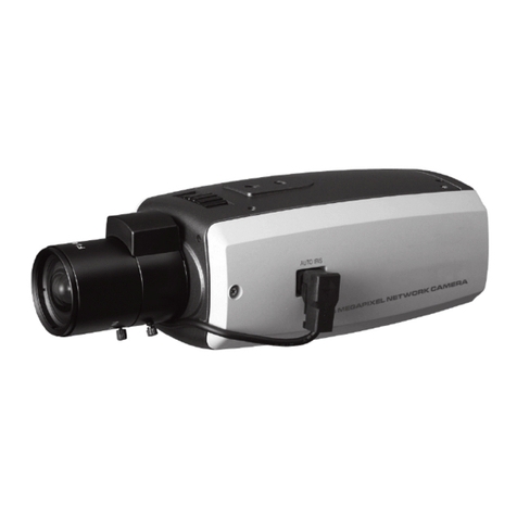
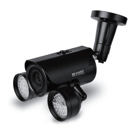
  9. KT&C KNC-Ni700HD User manual

KT&C KNC-Ni700HD User manual

3. Product Description
Description and Function
1. Infrared LED – These LEDs emit infrared radiation.
2. Sensor – Light sensor.
3. Service Video Connector – Outputs video to the monitor.
4. Factory reset – Factory reset button.
5. Status LED – LED to indicate camera status.
6. Network Connector – The Network Camera connects to the network via a standard
network cable, and automatically detects the speed of the local network segment
(10BaseT/100BaseTX Ethernet). PoE Supported.
7. Digital Input – Connects signal from external sensor.
8. Digital Output – Connects signal to external alarm. (Max. current - DC 12V, 70mA)
9. Power Input(DC12V) – Connect DC 12V power..
4. Dimensions
M124-Ni700/720HD-001
Megapixel Network Camera
KNC-Ni700HD / KNC-Ni720HD
Installation Guide
Table of Contents
1.INTRODUCTION
2.PACKAGE CONTENTS
3.PRODUCT DESCRIPTION
4.DIMENSIONS
5.INSTALLATION
6.IP ADDRESS ASSIGNMENT
7.TERMINAL BLOCK CONNECTORS
1. Introduction
KNC-Ni700HD, KNC-Ni720HD Installation Guide
This installation guide provides instructions for installing the Network Camera on your
network. For all other aspects of using the product, please see the User’s Manual,
available on the CD included in this package, or from http://www.ktnc.co.kr
Installation steps
1. Check the package contents against the list below.
2. Read the product description.
3. Install the hardware.
4. Set an IP address.
5. Set the admin and user ID and password. (See User’s Manual)
Important!
This product must be used in compliance with local laws and regulations.
2. Package Contents
KNC-Ni700HD / KNC-Ni720HD Screw-4ea Software CD
L Wrench and RJ45
coupler Service Video Output Test Cable Installation Guide
5. Installation
• Camera Mounting Position
• External Zoom & Focus Adjustment
• Connection
1. Connect the camera to the network using a UTP cable (CAT.5).
Power can be supplied via the network cable (PoE)
2. Connect DC 12V to the power terminal. This is not necessary if the Network Camera is
connected to a PoE hub or midspan.
3. Check that the indicator LEDs indicate the correct conditions.
4. Connect the analog monitor to the service video connector for adjusting focus, then press and quickly
release the reset switch for focus assistant mode.
Then you can select normal view or focus view mode using the reset switch.
Caution: When you use focus assistant mode, “Focus View” mode is recommended for more exact focus.
Caution: Focus assistant mode will be automatically exited after 3 minutes for normal operation.
Digital Input
Digital Output
< Cable Concealed Thru Bracket >
90
˚TLIT
360
˚PAN
360
˚PAN
90
˚TLIT
Opening the window cap to adjust the zoom and focus can cause humidity
problems in the camera. The External Zoom and Focus system with our
state-of-the-art technology provides easy camera installation without
opening the window cap to adjust zoom and focus the lens.
❶
❷
❸
❹
❺
❻
❼
❽
❾
6. IP Address Assignnt
To make it accessible on the network, the Network Camera must be assigned an IP address.
Note:
• A network DHCP server is optional.
• The Network Camera has the default IP address 192.168.0.123.
• If IP assignment fails, check that there is no firewall blocking its operation and check that the Network
Camera and your computer's IP is located on the same subnet.
Assign an IP address using IP Installer
The IP installer automatically searches for and display KT&C network devices on your network.
The application can also be used to manually assign a static IP address.
Note:
The computer running the IP installer must be on the same network segment (physical subnet) as the Network
Camera.
1. Check that the Network Camera is connected to the network and that power has been supplied.
2. Start KT&C IP installer.
3. When the Network Camera is displayed as shown above, select the unit that needs to be assigned an IP.
A. Refresh Device List – Rescan local network to nd the Network Camera.
B. Authenticate – Enter the administrator ID and password.
C. Host Name – Enter the Host Name of the Network Camera.
D. IP Settings
i. Dynamic – Assign dynamic IP address automatically from DHCP server on your network.
ii. Static – Assign static IP address manually.
iii. Port – Enter the HTTP port the Network Camera will use. The default setting is 80.
Alternatively, any port in the range 1024-65535 may be used, but check rst with your
system administrator before changing the default setting.
E. Network Settings
i. Subnet Mask – Specify the mask for the subnet the Network Camera is located on.
ii. Gateway – Specify the IP address of the default router (gateway) used for connecting
devices attached to different networks and network segments.
iii. Pri. DNS – Enter the IP address of the primary DNS server. This server provides the
translation of host names to IP addresses on your network.
iv. Sec. DNS – Specify the IP address of the secondary DNS server. This will be used if the
primary DNS server is unavailable.
4. Click the “Set” button to save the conguration.
Accessing the Network Camera
1. Start your browser(when you rst run ActiveX to install, run an “IE as Administrator” on Windows or Vista).
2. Enter the IP address or host name of the Network Camera in the Address eld of your browser.
3. If you are accessing the Network Camera for the rst time, you will see the following warning
message as shown below.
4. Click the warning message and select “Install ActiveX Control…”.
5. Click “Install” to install the KT&C Web Viewer.
6. If a Windows Security Alert pop-up appears, click “Unblock”.
7. After installing the KT&C Web View ActiveX Control, a Login page will be displayed.
Enter the user ID and password.
Note:
Default User ID and Password is [ID: admin, Password: admin]
8. The video image displays in your browser.
Note:
To view streaming video in Microsoft Internet Explorer, you must set your browser to allow the “KT&C Web Viewer” to
be installed on your computer. This ActiveX component is installed the first time a video stream is accessed.
7. Terminal Block Connectors
KNC-Ni700HD, KNC-Ni720HD are connected with external equipment as in the following diagram.
Circuit diagram
1. INPUT – Connect the external sensor e.g. PIR motion sensor. (3.3V DC pull-up built in)
A. ON - Short-circuit with GND.
B. OFF - Open
CAUTION : Digital Input must not be exposed to voltages greater than 10V DC.
2. OUT – Connect the external alarm e.g. light or buzzer.
CAUTION : If used with an external relay, a diode must be connected in parallel
with the load, for protection against voltage transients.
CAUTION : Max. load = 70mA Max voltage = 12V DC.
Example of terminal connection
KNC-Ni700HD
TERMINAL CONNECTION
This manual suits for next models

1

Other KT&C Security Camera manuals

KT&C KPC-S801DCHB Service manual

KT&C

KT&C KPC-S801DCHB Service manual

KT&C KPC-EW650U User manual

KT&C

KT&C KPC-EW650U User manual

KT&C KEZ-c2TR28V12XIR User guide

KT&C

KT&C KEZ-c2TR28V12XIR User guide

KT&C KPC DN100 User manual

KT&C

KT&C KPC DN100 User manual

KT&C KPC-HDN552MW User manual

KT&C

KT&C KPC-HDN552MW User manual

KT&C KNC-Xi130HD User manual

KT&C

KT&C KNC-Xi130HD User manual

KT&C HDX131M User manual

KT&C

KT&C HDX131M User manual

KT&C Omni-ip User guide

KT&C

KT&C Omni-ip User guide

KT&C KPC-E650U User manual

KT&C

KT&C KPC-E650U User manual

KT&C KNC-HMB6319-iWX User manual

KT&C

KT&C KNC-HMB6319-iWX User manual

KT&C KNC-HDi47 User manual

KT&C

KT&C KNC-HDi47 User manual

KT&C AVN82V User manual

KT&C

KT&C AVN82V User manual

KT&C KNC-HDDi100 User manual

KT&C

KT&C KNC-HDDi100 User manual

KT&C KNC-SPDNi300 User manual

KT&C

KT&C KNC-SPDNi300 User manual

KT&C KPC-VDN101 User manual

KT&C

KT&C KPC-VDN101 User manual

KT&C KPC-VNW101NHV15 User manual

KT&C

KT&C KPC-VNW101NHV15 User manual

KT&C KNC-Xi130HD User manual

KT&C

KT&C KNC-Xi130HD User manual

KT&C M173-LD(N)Di45-001 User manual

KT&C

KT&C M173-LD(N)Di45-001 User manual

KT&C KPC-LDD45NU User manual

KT&C

KT&C KPC-LDD45NU User manual

KT&C M232-N702-001 User manual

KT&C

KT&C M232-N702-001 User manual

KT&C KPC-DQ100NHB User manual

KT&C

KT&C KPC-DQ100NHB User manual

KT&C KPT-SPDN231NH User manual

KT&C

KT&C KPT-SPDN231NH User manual

KT&C OMNI-IP KNC-p3BR4XIR User guide

KT&C

KT&C OMNI-IP KNC-p3BR4XIR User guide

KT&C KPT-SPDN300 User manual

KT&C

KT&C KPT-SPDN300 User manual

Popular Security Camera manuals by other brands

TP-Link NC250 quick start

TP-Link

TP-Link NC250 quick start

Monacor TVCCD-35 COL operating instructions

Monacor

Monacor TVCCD-35 COL operating instructions

Vivotek FD9365-HTVL user manual

Vivotek

Vivotek FD9365-HTVL user manual

EverFocus EHN3160 Plus user manual

EverFocus

EverFocus EHN3160 Plus user manual

D-Link DCS-7010L Quick installation guide

D-Link

D-Link DCS-7010L Quick installation guide

Northern CB700VFIR5960 user manual

Northern

Northern CB700VFIR5960 user manual

ZMODO ZP-KB1I04-W quick start guide

ZMODO

ZMODO ZP-KB1I04-W quick start guide

Reolink Go PT user manual

Reolink

Reolink Go PT user manual

jablotron JA-110C Installation

jablotron

jablotron JA-110C Installation

Honeywell HCS544 Specifications

Honeywell

Honeywell HCS544 Specifications

Samsung SCC-B2005P Specifications

Samsung

Samsung SCC-B2005P Specifications

CamCuddle W8 user manual

CamCuddle

CamCuddle W8 user manual

Novus NVIP-6DN5021H/IRH-1P user manual

Novus

Novus NVIP-6DN5021H/IRH-1P user manual

Axis Q1615-LE Mk III user manual

Axis

Axis Q1615-LE Mk III user manual

Vimar ELVOX TVCC 46212.036B.01 quick start guide

Vimar

Vimar ELVOX TVCC 46212.036B.01 quick start guide

Prisual TEM-30V user manual

Prisual

Prisual TEM-30V user manual

Panasonic WV-SFR631L installation guide

Panasonic

Panasonic WV-SFR631L installation guide

Digital Watchdog STAR-LIGHT AHD DWC-V7753TIR manual

Digital Watchdog

Digital Watchdog STAR-LIGHT AHD DWC-V7753TIR manual

manuals.online logo
manuals.online logoBrands
  • About & Mission
  • Contact us
  • Privacy Policy
  • Terms and Conditions

Copyright 2025 Manuals.Online. All Rights Reserved.