Kubler 901 User manual

deutschenglishfrançais
italiano
español
Bedienungsanleitung
Elektronischer Vorwahlzähler
Typ 901
1.1 Vorwort
Lesen Sie vor der Montage und der
Inbetriebnahme diese Bedienungs-
anleitung aufmerksam und voll-
ständig durch. Beachten Sie zu
Ihrer eigenen Sicherheit und der
Betriebssicherheit alle Warnungen
und Hinweise. Wenn das Gerät nicht
nach dieser Bedienungsanleitung
benutzt wird, kann der vorgesehene
Schutz beeinträchtigt werden.
1.2 Sicherheits- und Warnhinweise
Benutzen Sie das Gerät nur in
technisch einwandfreiem Zustand,
bestimmungsgemäß, sicherheits- und
gefahrenbewusst unter Beachtung
dieser Bedienungsanleitung.
Defekte oder beschädigte Geräte
müssen unverzüglich von sämtlichen
Stromkreisen getrennt und außer
Betrieb genommen werden.
Eine Instandsetzung darf nur durch
den Reparaturservice des Herstell-
ers erfolgen.
Das Gerät darf nur zum Wechseln
der Batterie geöffnet werden. Hierzu
ist das Gerät von allen Stromkreisen
zu trennen, bzw. spannungsfrei zu
schalten.
Schließen Sie das Gerät nur an die
dafür vorgesehenen Stromnetze an.
Die Sicherheit des Systems in
welches das Gerät integriert wird,
ist in der Verantwortung des Ein-
richters.
Trennen Sie für Installations- und
Wartungsarbeiten sämtliche Strom-
kreise.
Verwenden Sie nur für Ihr Land
zugelassene, für Ihre Temperatur-
und Leistungsbereich ausgelegte
Kabel.
Installations- und Servicearbeiten
dürfen nur von einer Fachkraft aus-
geführt werden.
Das Gerät muss zwingend mit
externen, zugelassenen Sicherun-
gen abgesichert werden. Den Wert
entnehmen Sie den technischen
Daten.
Das auf dem Gerät verwendete
Symbol soll darauf hinweisen, dass
es Gefahren gibt, auf die in dieser
Anleitung hingewiesen wird.
1.3 Bestimmungsgemäßer Gebrauch
Der Vorwahlzähler 901 erfasst Impulse und
Zeiten bis max. 30 Hz und bietet verschiedene
Betriebsarten. Gleichzeitig verarbeitet der Vor-
wahlzähler eine programmierte Vorwahl. Jeder
darüber hinausgehende Gebrauch gilt als nicht
bestimmungsgemäß.
Der Einsatzbereich dieses Geräts liegt in
industriellen Prozessen und Steuerungen von
Fertigungsstraßen der Metall-, Holz-, Kunst-
stoff-, Papier-, Glas- und Textilindustrie u.ä..
Überspannungen an den Schraubklemmen
des Geräts müssen auf den Wert der Übers-
pannungskategorie II begrenzt werden. Das
Gerät darf nur im ordnungsgemäß eingebauten
Zustand und entsprechend dem Kapitel „Tech-
nische Daten“ betrieben werden.
Das Gerät ist nicht geeignet für den explosions-
geschützten Bereich und den Einsatzbereichen,
die in EN 61010-1 ausgeschlossen sind. Wird
das Gerät zur Überwachung von Maschinen
oder Ablaufprozessen eingesetzt, bei denen
infolge eines Ausfalls oder Fehlbedienung des
Gerätes eine Beschädigung der Maschine oder
ein Unfall des Bedienungspersonals möglich ist,
dann müssen Sie entsprechende Sicherheits-
vorkehrungen treffen.
Das Gerät ist für die Verwendung in Innenräu-
men konzipiert. Bei Einhaltung der technischen
Daten kann das Gerät aber auch im Außen-

bereich verwendet werden. Achten Sie hierbei
aber auch auf einen angemessenen UV-Schutz.
1.4 Schalttafeleinbau
Montieren Sie das Gerät entfernt
von Wärmequellen und vermeiden
Sie direkten Kontakt mit ätzenden
Flüssigkeiten, heißem Dampf oder
ähnlichen.
Es muss sichergestellt werden, dass
umlaufend um das Gerät 10 mm
Umlüftung vorhanden ist.
Das Gerät muss so eingebaut
werden, dass die Anschlussklem-
men von einem Bediener unzugän-
glich und nicht berührbar sind.
Beachten Sie beim Einbau, dass
nur die Frontseite als Bediener-
berührbar eingestuft ist.
1.5 Montageanleitung
1. Befestigungsrahmen vom Gerät abziehen.
2. Gerät von vorne in den Schalttafelausschnitt
einsetzen und auf korrekten Sitz der Fron-
trahmendichtung achten.
3. Befestigungsrahmen von hinten auf das
Gehäuse aufschieben, bis die Federbügel
unter Spannung stehen und die Rastnasen
oben und unten eingerastet sind.
Hinweis: Bei fachgerechtem Einbau kann front-
seitig IP65 erreicht werden.
1.6 Elektrische Installation
Dieses Gerät wird mit einer internen Batterie
versorgt.
Trennen Sie vor Installations- oder
Wartungsarbeiten das Gerät von
allen Spannungsquellen und stellen
Sie sicher, dass keine BERÜHR-
GEFÄHRLICHEN Spannungen
mehr vorhanden sind.
Installations- oder Wartungsarbe-
iten dürfen nur von einer Fachkraft
durchgeführt werden und müssen
nach den zutreffenden nationalen
und internationalen Standards
erfolgen.
Es muss darauf geachtet werden,
dass sämtliche Kleinspannungen
welche in das Gerät gehen oder
aus dem Gerät kommen durch dop-
pelte bzw. verstärkte Isolation von
gefährlichen, stromführenden Lei-
tungen getrennt sind (SELV Kreise).
Das Gerät muss für den ordnungs-
gemäßen Betrieb extern abgesichert
werden. Hinweise für die vorge-
schriebenen Sicherungen finden Sie
unter den Technischen Daten.
Der Relaisausgang ist geräteintern
nicht abgesichert / überstrombe-
grenzt. Ohne entsprechende
Absicherung des Relaisausgangs
kann es zu unerwünschter Wär-
meentwicklung oder sogar zum
Brand kommen. Der Relaisausgang
ist vom Errichter der Anlage extern
abzusichern. Es muss auch im Feh-
lerfall sichergestellt werden, dass
die unter den technischen Daten
angegebenen Daten auf keinen
Umständen überschritten werden.
Bei der Installation muss darauf geachtet
werden, dass die Spannung des Zähl- und
Rückstelleingangs und die Beschaltung des
Ausgangskontakts von der gleichen Netzphase
versorgt werden, damit die max. Spannung von
250V nicht überschritten wird.
Leitungen und deren Isolierungen müssen dem
vorgesehenen Temperatur- und Spannungsbe-
reich entsprechen. Für die Beschaffenheit der
Leitungen sind die zutreffenden Standards des
Landes und des Endgerätes einzuhalten. Die
zulässigen Querschnitte für die Schraubbefesti-
gungen finden Sie in den technischen Daten.
Überprüfen Sie vor der Inbetriebnahme den
korrekten und festen Sitz der Leitungen. Nicht
benutzte Schraubklemmen müssen bis zum
Anschlag eingeschraubt werden damit sich
diese nicht lösen und verlieren.
Seite 2 | DEU
VORSICHT
GEFAHR
GEFAHR

1.8 Inbetriebnahme
• Ist das Gerät richtig eingestellt und programmi-
ert (Funktion; bei Zählern max. Zählfrequenz)?
1.9 Fehlermöglichkeiten und deren Ursachen
Tastatur lässt sich nicht bedienen:
• Tastaturverriegelungseingang aktiviert
Zähler zählt nicht:
• Zähleingang falsch oder verdreht angeschlossen
• Falsches Eingangssignal für den Impulsgeber
eingestellt
• keine Masseverbindung zwischen Impulsgeber
und Zähler
• Signalpegel erreichen die Schaltschwelle des
Zählers nicht
Relais-Ausgangssignal fehlt:
• Ausgangskontakt kurzgeschlossen
• Ausgangssignal (Wischzeit) zu kurz programmiert
• Relaiskontakt durch zu hohe Belastung defekt
• min. Relaisstrom unterschritten
Anzeige noFunc:
• Batterie ist leer und muss getauscht werden.
Sollte Ihr Gerät trotz allem nicht funktionieren,
so wenden Sie sich bitte an die für Sie zustän-
dige Vertretung ganz in Ihrer Nähe, oder rufen
Sie direkt bei der technischen Beratung in
unserem Hause an.
Bei Rücksendungen bitten wir um eine kurze
Beschreibung des Fehlers, der Programmierung
und des Anschlussbildes, um einen eventuell
vorhandenen Fehler nachvollziehen und eine
Reparatur Ihres Gerätes möglichst schnell
durchführen zu können.
2. Eingänge
2.1 Rücksetzeingang Pin 6
Dieser Eingang ist funktionell mit der roten Set-
Taste parallel geschaltet und setzt den Zähler
bei addierender Zählweise auf Null, bei subtra-
hierender Zählweise auf den Vorwahlwert. Die
Rücksetzfunktion ist dynamisch.
deutsch
Seite 3 | DEU
Das Gerät ist für die Überspannungskategorie II
ausgelegt. Wenn nicht ausgeschlossen werden
kann, dass höhere transiente Überspannun-
gen auftreten können, müssen zusätzliche
Schutzmaßnahmen installiert werden, welche
die Überspannungen auf die Werte der CAT II
begrenzen.
Hinweise zur Störsicherheit
Alle Anschlüsse sind gegen äußere Störe-
inflüsse geschützt. Der Einsatzort ist so
zu wählen, dass induktive oder kapazitive
Störungen nicht auf das Gerät oder dessen
Anschlussleitungen einwirken können! Durch
geeignete Kabelführung und Verdrahtung kön-
nen Störeinflüsse (z.B. von Schaltnetzteilen,
Motoren, getaktete Reglern oder Schützen)
vermindert werden.
Erforderliche Maßnahmen
• Für Signal- und Steuerleitungen nur geschirm-
tes Kabel verwenden. Kabelschirm beidseitig
auflegen. Litzenquerschnitt der Leitungen min.
0,14 mm2.
• Der Anschluss der Abschirmung an den
Potentialausgleich muss so kurz wie möglich
und großflächig (niederimpedant) erfolgen.
• Verbinden Sie die Abschirmungen nur mit der
Schalttafel, wenn diese auch geerdet ist.
• Das Gerät muss in möglichst großem Abstand
von Leitungen eingebaut werden, die mit
Störungen belastet sind.
• Leitungsführungen parallel zu Energieleitungen
vermeiden.
1.7 Reinigung und Wartung
Die Frontseite darf nur mit einem weichen, mit
Wasser angefeuchteten Tuch gereinigt werden.
Eine Reinigung der eingebauten Rückseite ist
nicht vorgesehen und obliegt der Verantwortung
des Servicepersonals oder Installateurs.
Bei einem normalen Betrieb ist dieses Gerät
wartungsfrei. Sollte das Gerät wiedererwartend
nicht ordnungsgemäß funktionieren, muss
das Gerät an den Hersteller oder Lieferanten
geschickt werden. Ein eigenmächtiges öffnen
und instand setzen ist nicht vorgesehen und
kann den ursprünglichen Schutz beeinträchtigen.

Seite 4 | DEU
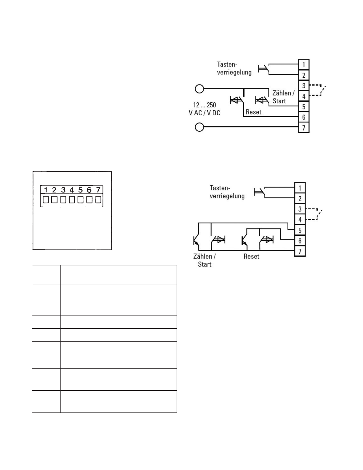
2.2 Zähleingang (Starteingang) Pin 5
Auf 25 Hz bedämpfter Eingang für die Impuls-
zählung beim Impulsvorwahlzähler oder sta-
tischer Starteingang beim Zeitvorwahlzähler
(Zeitzählung aktiv bei aktivem Eingang, Zeitindi-
kator oben links blinkt bei aktiver Zeitzählung).
Hinweis: Der Rücksetzeingang (Pin 6) und der
Zähleingang (Pin 5) sind Eingänge mit gemein-
samem Anschluss (Pin 7) und müssen mit der
gleichen Polarität angesteuert werden.
2.3 Tastaturverriegelungseingang
Wird dieser Eingang (Pin 2) auf +3 VDC (Pin 1)
gelegt, sind die Fronttasten (auch die Set-Taste
gesperrt).
3. Ausgang
Relais mit potentialfreiem, als Schließer oder
Öffner programmierbarem Kontakt (Pin 3 und
Pin 4). Bei addierender Zählweise ist das Relais
bei > Vorwahl, bei subtrahierender Zählweise
bei < 0 aktiv. Das Ausgangssignal ist program-
mierbar als Wischimpuls von 0,1 bis 99,9 sec.
oder bistabil bei der Einstellung 0.0 (Loop OFF)
keine automatische Wiederholung. Bei aktivem
Relais erscheint in der unteren Reihe, links
auf dem Display, ein Doppelpunkt. Die Schalt-
frequenz des Ausgangsrelais darf 4 Hz nicht
überschreiten.
4. Einstellung der Betriebsart und der
Betriebsparameter
4.1 Neuinstallation
Bei einer Neuinstallation des Zählers, oder
nach einem Batteriewechsel der länger als 20s
gedauert hat, oder wenn der Zähler wegen
zu geringer Batteriespannung in den Sicher-
heitsmode „NoFunc“ geschaltet hat, wird der
Vorwahlzähler automatisch in den Programmier-
modus geschaltet und alle Parameter müssen
neu eingegeben werden (siehe 4.2).
Eine Änderung der Parameter ist auch während
des Betriebs möglich. Um hier in den Program-
miermodus zu kommen, müssen aus Sicher-
heitsgründen die Reset-Taste und die Tasten
der 5. und 6. Dekade gleichzeitig gedrückt
werden. Auf dem Display erscheint dann in der
unteren Zeile INIT. Bleiben diese 3 Tasten wei-
terhin gedrückt, dann zählt ein Rückwärtszähler
im Sekunden-Takt von 5 bis Null. Werden
innerhalb dieser Zeit die Tasten losgelassen,
dann wird die vorher aktuelle Betriebsart wieder
eingestellt. Werden erst beim Erreichen von Init
0 die Tasten losgelassen, ist die Parameterein-
stellung aktiviert und der erste Parameter wird
auf dem Display angezeigt.
4.2 Einstellung der Parameter
Mit der Taste der 1. Dekade wird zwischen
den verfügbaren Parametern umgeschaltet
(z.B. add-sub) und mit der Taste der 6. Dekade
wird in die nächste Funktion umgeschaltet. Die
Wischimpulszeit wird mit den Dekadentasten
1-3 eingestellt. Nach der letzten Eingabe (dP)
kann mit der 6. Dekade an den Anfang der
Programmierroutine gesprungen werden, oder
durch gleichzeitigem Drücken der Reset-Taste
und den Tasten der 5. und 6. Dekade die Para-
meter gespeichert werden.
Hinweis: Bei jedem Aufruf der Programmierrou-
tine geht der Zähler in die Parametergrundein-
stellung, d.h., die alte Programmierung geht ver-
loren und der Zählerstand und der Vorwahlwert
werden auf Null gesetzt.
4.3 Beschreibung der Parameter
(siehe auch Funktionsablauf)
Funct.Count: Betriebsart Impulsvorwahlzähler
Funct.Time: Betriebsart Zeitvorwahlzähler
tMode: programmierbarer Zeitbereich (nur
bei Funct.Time), SEC=Sekunden,
Min=Minuten, hour=Stunden
Count Add: addierende Zählweise
Count Sub: subtrahierende Zählweise
LooP off: Automatische Wiederholung Aus
Bei Parameter LooP “off” und
einer dELAY time 0.0, wird nach
Erreichen des Vorwahlwerts der
Ausgang aktiv, bis ein Reset
durchgeführt wird.
LooP on: Automatische Wiederholung Ein
Beim Parameter LooP “on”, wird
der Zähler automatisch zurückge-
stellt, der Ausgang entsprechend
der bei dELAY eingestellten Zeit
als Wischimpuls aktiv.
rELAY no: Ausgang Schließer (normally open)

wird. In diesem Mode werden keine Impulse und
Zeiten mehr gezählt und das Relais bleibt in der
letzten Position ruhen. Somit weiß der Benutzer
ganz genau, ob die Anlage noch optimal arbei-
tet und es wird einer Fehlfunktion vorgebeugt.
Nach Wechsel der Batterien im „noFunc“ Modus
muss das Gerät neu parametriert werden. Bitte
lesen Sie hierzu das Kapitel Batteriewechsel.
Hinweis: Um zu verhindern das
Einstellungen und Werte durch den
Sicheren Mode verloren gehen
sollte der Serviceplan für das Gerät
den Batteriewechsel in Abhängigkeit
von Temperaturumgebung und
Schaltspiele des Relais rechtzeitig
eingeplant werden.
5.5 Batteriewechsel
Trennen Sie vor dem Batteriewechsel die
Spannungen oder schalten Sie das Gerät span-
nungsfrei. Ziehen Sie den Steckverbinder am
Gerät ab. Damit ist auch sichergestellt das wäh-
rend dem Batteriewechsel keine unbeabsich-
tigten Impulse das Gerät in einen undefinierten
Zustand bringt. Danach den Batteriedeckel nach
hinten schieben und die 2 Batterien entfernen.
Die neue Batterie so einsetzen, dass der „-”Pol
mit dem auf der Leiterplatte mit „-” gekennzeich-
neten Batteriehalter verbunden ist. Nach dem
Wechseln der Batterien kann in der Anzeige
noch für weitere 2 Minuten die Anzeige LowBat
angezeigt werden. Durch betätigen der Resetta-
ste kann die Wartezeit verkürzt werden, da das
Gerät bei jedem Betätigen die aktuelle Batterie-
spannung überprüft. Dabei wird jedoch auch der
aktuelle Zählerstand zurückgesetzt.
Wichtig: Dauert der Batteriewech-
sel länger als 20 Sekunden können
die Parameter, Vorwahlwerte und
der Zählerstand gelöscht werden.
Um diesen Informationsverluste zu
vermeiden empfehlen wir dringend
eine Batterie nach der anderen aus-
zuwechseln.
deutsch
Seite 5 | DEU
rELAY nc: Öffner (normally closed)
dELAY: Ausgangssignalzeit: Wischsignal
programmierbar von 00.1 – 99.9
Sekunden, 0.0 = bistabiler Aus-
gang (aktiv bis Rücksetzen) pro-
grammierbar nur bei Loop off, bei
Loop on springt 0.0 automatisch
auf 1.0 Sekunden
dP: Programmierbarer Dezimalpunkt:
Impulsvorwahlzähler: 0 - 0.00000
nur anzeigend, Zeitvorwahlzähler
0 – 0.0 (Sekunden) 0 – 0.00 (Minu-
ten, Stunden) legt die Auflösung
fest. Wird der Relaisausgang von
„no“ auf „nc“ geändert, muss der
Relaiszustand durch Betätigen der
Resettaste übernommen werden.
5. Bedienung des Zählers
5.1 Setzen oder Rücksetzen
Mit der roten Set-Taste oder einem Impuls auf
den Rücksetzeingang wird der Zähler bei addie-
render Zählweise auf Null, bei subtrahierender
Zählweise auf den Vorwahlwert gesetzt.
5.2 Vorwahleinstellung
Der Vorwahlwert wird in der unteren Ziffernreihe
angezeigt. Die Einstellung erfolgt über die 6,
jeder Dekade zugeordneten Vorwahltasten. Der
eingestellte bzw. veränderte Vorwahlwert wird,
mit dem nächsten Setzen oder Rücksetzen des
Zählers übernommen.
5.3 Über- bzw. Unterlauf
Bei addierender Zählweise ist der Überlauf
999999 auf Null, bei subtrahierender Zählweise
von Null auf 999999. Das Ausgangssignal bleibt
unbeeinflusst. Bei Über- bzw. Unterlauf blinkt
die Anzeige. Nach Über- bzw. Unterlauf einer
weiteren Dekade bleibt der Zähler stehen.
5.4 Lo-Bat-Indikator
Bei zu geringer Kapazität der Batterie erscheint
in der unteren Anzeige Lo-bat, die Anzeige
blinkt. Bei „Lo-bat“-Anzeige müssen die Batte-
rien ausgewechselt werden. Sollte die Batterie-
spannung soweit absinken dass ein sicheres
Schalten des Relais nicht mehr gewährleistet
werden kann, geht der Zähler in den Sicheren
Mode, was mit der Anzeige „noFunc“ angezeigt

Seite 6 | DEU
Verwenden Sie nur Batterien welche in den
technischen Daten beschrieben werden.
Andernfalls kann eine korrekte Funktion nicht
gewährleistet werden.
5.6 Segmenttest
Ein Segmenttest wird aktiviert, durch gleichzei-
tiges Drücken der Tasten Reset sowie 5. und 6.
Dekadentaste. Danach erscheint im Display Init
5, nun sofort die Tastenkombination lösen, der
Segmenttest wird ausgelöst und alle Segmente
im Display angezeigt. Durch Betätigen der 1.
Segmenttaste wird in den Programmiermodus
gesprungen und alle Parameter müssen neu
programmiert werden.
6. Anschlussbelegung
Klemme
Nr.
1+3 VDC für Tastaturverriegelung auf
Klemme 2
2 Tastaturverriegelungseingang
3 Relaiskontakt
4 Relaiskontakt
5
AC/DC Optokoppler Zähleingang /
Starteingang (.820) / NPN Zählein-
gang / Starteingang (.850)
6AC/DC Optokoppler-Rücksetzeingang
(.820) / NPN-Rücksetzeingang (.850)
7gemeinsamer AC/DC-Eingang (.820) /
0V Eingang (.850) für Klemme 6 und 5
7. Anschlussbeispiel
Gerätetyp:
x.901.xxx.820
12 ... 250 VAC/VDC
V AC/DC
Gerätetyp:
x.901.xxx.850
NPN
8. Werkseitige Programmierung:
Funktion(Funct): Zähler(Count)
Zählweise(Count): addierend(add)
Autom. Wiederholung(LooP):
keine(oFF)
Ausgangskontakt(rELAY):
Schließer(n.o.)
Ausgangsignalzeit(dELAY):
bistabiler Ausgang (0.0)
Dezimalpunkt(dP): keiner(0)

Einsatzgebiet: Verschmutzungsgrad 2
Isolation
Frontseitig: Doppelte /
Verstärkte Isolierung
Relais: Basisisolierung
UL-Zulassung: File-Nr.: E128604
10.3 Mechanische Kennwerte
Schutzart: IP65 (frontseitig)
Gewicht: ca. 80 g
10.4 Eingänge
Eingänge: Eingänge Rücksetz-,
Zähl- und Tastaturverrie-
gelungseingang
Polarität der Eingänge
(für Rücksetz- und Zähl-/Starteingang):
12 ... 250 V AC/DC: bidirektionaler Optokopp-
ler-Eingang
NPN: NPN-Eingang der über
Transistor oder Kontakt
aktiviert wird
Tastaturverriegelungs-Eingang:
wird auf +3 V DC
geschaltet (Klemme 1)
Mindestimpulsdauer der Eingänge:
Rücksetzeingang: 50 ms
Tastaturverriegelung: 15 ms
Schaltpegel der Eingänge:
12 ... 250 V AC/DC: LOW: < 1 V AC/DC
HIGH: 12...250 V AC/DC
NPN: LOW: 0 ... 0,8 V DC
HIGH: 2,5 ... 30 V DC
Eingangsfrequenz
Impulszähler: max. 30 Hz
Zeitzähler: Messimpulse
< 200 ms werden nicht
genau erfasst
Genauigkeit: Systemfehler +/- 100 ms
pro Messimpuls
Zeitgenauigkeit: 200 ppm
Eingangswiderstand: 110 kΩ
deutsch
Seite 7 | DEU
9. Entstörmaßnahmen
Folgende Entstörmaßnahmen können not-
wendig sein: Schaltet der Ausgang induktive
Lasten (Relais, Magnet-ventile), so sind diese
bei Gleichstrom durch eine Freilaufdiode, bei
Wechselstrom durch ein RC-Glied zu entstören.
Für den sicheren und EMV sicheren Betrieb
sind für die Steuereingänge (Zähl-, Rücksetz-
und Tastaturverriegelungs-eingang) geschirmte
Kabel zu verwenden. Die Abschirmung muss
beidseitig aufgelegt werden. Ist dies nicht
möglich kann auf einer Seite ein Kondensator
(z.B. 10 nF) in die Schirmverbindung eingebaut
werden.
10. Technische Daten
10.1 Allgemeine technische Daten
Anzeige: 2-zeilige LCD-Anzeige,
jeweils 6 Stellen 999999;
7 bzw. 4,5 mm hoch
Betriebstemperatur: -20°C ... +65°C
(nicht betauend)
Lagertemperatur: -25°C ... +70°C
Höhe: bis 2000 m
10.2 Elektrische Kennwerte
Spannungs- 2 Stück auswechselbare
versorgung: Lithium-BatterienTyp 1/2
AA Lithium 3,6 V
Datensicherung: min. 8 Jahre bei 5 x 10⁶
Schaltspielen des Aus-
gangsrelais und 25°C
Betriebstemperatur
EMV
Störaussendung: EN 55011 Klasse B
Störfestigkeit: EN 61000-6-2,
EN 61326-1
Gerätesicherheit
Auslegung nach: EN 61010
Schutzklasse: 2 (frontseitig)
nur die Frontseite ist Bedienerbe-
rührbar eingestuft.

Seite 8 | DEU
10.5 Ausgänge
Ausgänge: bistabiles Relais mit
potentialfreiem Kontakt –
als Schließer oder Öffner
programmierbar
Max. Schaltspannung: 250 V AC / 30 V DC
Max. Schaltstrom: 2 A
Max. Schaltleistung: 60 VA / 30 W
Mechanische Lebensdauer:
1x10⁷
Elektrische Lebensdauer:
5x10⁵(1A 30Vdc)
Ansprechzeit des Ausgangs:
< 20 ms, max. 4 Hz
Isolationskoordinaten: Basisisolierung
UL Ratings: 2A, 30Vdc, 50°C
10.6 Sicherungen / Überstrombegrenzungen
Eingangssignale: Im Fehlerfall muss der Strom
über die Eingänge auf ein ungefährliches Maß
begrenzt werden. Wir empfehlen eine Sicherung
von 0,1A/T.
Relais: Der Maximale Schaltstrom von 2A darf
auf keinen Fall überschritten werden.
10.7 Anschlüsse
Steckbare Schraubklemme, 7-polig, RM5,08,
Aderquerschnitt, max. 2,5 mm.
10.8 Isolationskoordinaten
Anschlüsse untereinander
x.901.xxx.820: nur Zähl- und Rücksetzeingang
haben doppelte / verstärkte Isolierung
x.901.xxx.850: generell nur Basisisolierung
10.9 Verbrauchsmaterial
Batterie: Bestell Nr: N060045 Tadiran Lithium
SL350/S ½ AA 3,6V 1,2Ah

<5s <1s
Init 5 Init 4,3,2, 1 Init 0
8.8.8.8.8.8
:
8.8.8.8.8.8
Funct.
Count
Funct.
tImE
tModE
hour
, Min, SEC
Count
Add, Sub
Count
Add, Sub
LooP
oFF;on
LooP
oFF;on
rELAY
no, nc
rELAY
no, nc
dELAY
01.0
dELAY
01.0
dP
0, 0.0, 0.00, 0.000,
0.0000, 0.00000
dP
SEC: 0, 0.0
hour+Min: 0, 0.0, 0.00
SAVE 1-2 Sec
=5s
1
6
6
1
1
6
1
6
1
6
1
6
1
6
1
2
3
6
1
6
1
1
6
6
1
6
1
2
3
6
1
1
<20s
>20s
1
deutsch
Seite 9 | DEU
11. Programmiermenü
Gleichzeitig
Reset-Taste
und Tasten der
5. u. 6. Dekade
drücken
Rückwärtszähler im
Sekunden-Takt Zeit für
Batteriewechsel
Batteriewechsel
Betriebsart
Segmenttest
Einen Wert
wählen
Einen Wert
wählen
Einen Wert
wählen
Einen Wert
wählen
Einen Wert
ändern
Einen Wert
wählen
Einen Wert
wählen
Einen Wert
wählen
Einen Wert
wählen
Einen Wert
ändern
Einen Wert
wählen
Gleichzeitig
Reset-Taste
und Tasten der
5. u. 6. Dekade
drücken
Betriebsart
Sprung zum näch-
sten Paramenter
Parameter ändern

Seite 10 | DEU
13. Lieferumfang:
Zähler 901
2 Lithium-Batterien
1 Schraubklemme
1 Frontrahmen für Schraubbefestigung, Einbau-
querschnitt 50 x 50 mm
1 Frontrahmen für Spannbügelbefestigung, Ein-
bauquerschnitt 50 x 50 mm
1 Spannbügel
1 Schablone für Schalttafelausschnitt
1 Bedienungsanleitung
14. Bestellnummer:
6.901.x10.8y0
2 = Eingänge 12 … 250 V AC/DC
5 = Eingänge NPN
0 = Kübler
A = Neutral
15. Batterieverordnung:
Dieses Gerät enthält eine Lithium-Bat-
terie. Gemäß der Batterieverordnung
weisen wir Sie auf Folgendes hin:
Batterien gehören nicht in den Restmüll, sondern
Sie sind gesetzlich zur Rückgabe verpflichtet.Sie
können die kompletten Geräte nach Gebrauch
zu uns zurückschicken. Falls Sie die Batterien
fachgerecht ausbauen können, dürfen Sie diese
auch in einer kommunalen Sammelstelle oder im
Handel vor Ort zurückgeben.
Rückgabe-Bestimmungen speziell für Lithium
Batterien:
Vermeiden Sie Kurzschluss! Kleben Sie daher die
Pole der Batterie mit Isolierband ab. Die Pole der
Lithium-Batterie dürfen weder versehentlich noch
vorsätzlich mit Metallgegenständen in Berührung
kommen!
Schadstoffhaltige Batterien sind mit einem Zei-
chen, bestehend aus einer durchgestrichenen
Mülltonne und dem chemischen Symbol des für
die Einstufung als schadstoffhaltig ausschlag-
gebenden Schwermetalls versehen. Danke für
Ihre Mithilfe!
12. Abmessung
Maße in mm [inch]

english
Page 1 | ENG
Operating instructions
Electronic preset counter
Type 901
1.1 Foreword
Please read this instruction manual
entirely and carefully before installa-
tion and start-up. Please observe all
warnings and advices, both for your
own safety and for operating safety.
The intended protection can be
impaired If the device is not used
in accordance with this instruction
manual.
1.2 Safety instructions and warnings
Please use the device only if its
technical condition is perfect. It
should be used only for its intended
purpose, in accordance with this
instruction manual.
Defective or damaged devices
should be disconnected from the
mains immediately and taken out of
operation.
Repair work may be performed
only by the manufacturer‘s repairs
service.
This device may be opened only
for battery replacement. For this
purpose, the device must be sepa-
rated from all electric circuits and
de-energized.
Only connect the device to the
electricity networks provided to that
purpose.
The safety of the system in which
the device is integrated is the
responsibility of the installer.
Disconnect all electricity networks
prior to any installation or mainte-
nance work.
Use exclusively cables approved in
your country and designed for your
temperature and power ranges.
Installation and service work shall be
carried out exclusively by qualified
personnel.
The device must compulsorily be
protected with approved external
fuses. The value of these fuses
can be found in the technical
information.
This symbol is used on the device
to remind of the existence of dan-
gers, which are referred to in this
manual.
1.3 Use according to the intended purpose
The preset counter 901 counts pulses and
times up to max. 30 Hz and offers various
operating modes. The present counter simulta-
neously processes a programmed preset value.
Any other use is considered as non compliant
with the intended use.
The application area for this device lies in
industrial processes and controls, in the fields
of manufacturing lines for metal, wood, plastics,
paper, glass, textile and other like industries.
Overvoltages at the terminals of the device
must be kept within the limits of Overvoltage
Category II. The device must only be operated
when properly mounted in a panel and in accor-
dance with the section “Technical Data”.
The device is not suitable for use in areas with
explosion protection and for areas excluded in
EN 61010-1. If the device is used to monitor
machines or processes in which, in the event of
a failure of the device or an error made by the
operator, there might be the risk of damaging
the machine or causing an accident to the
operators, it is your responsibility to take the
appropriate safety measures.
The device has been designed for indoor ope-
ration. It may nevertheless be used outdoors,
provided the technical data is complied with.
In this case, take care to provide suitable UV
protection.

Page 2 | ENG
1.4 Mounting in a control panel
Mount the device away from heat
sources and avoid direct contact
with corrosive liquids, hot steam or
the like.
Provide a free space of 10 mm all
around the device for its ventilation.
The device should be mounted so
that the terminals are out of the
reach of the operator and cannot be
touched by him. When mounting the
device, consider the fact that only
the front side is classified as acces-
sible for the operator.
1.5 Mounting instructions
1. Remove the mounting clip from the device.
2. Insert the device from the front into the panel
cut-out, ensuring the front-panel gasket is
correctly seated.
3. Slide the fixing clip from the rear onto the
housing, until the spring clamps are under
tension and the upper and lower latching lugs
have snapped into place.
Note: In case of proper installation, IP65 can be
reached on the front side.
1.6 Electrical installation
This device is powered by an internal battery.
The device must be disconnected
from any power supply prior to any
installation or maintenance work.
Make sure that no more voltages
LIABLE TO CAUSE AN ELECTRO-
CUTION are present.
Installation or maintenance work
may only be carried out by qualified
personnel and in compliance with
the applicable national and internati-
onal standards.
Take care to separate all extra-low
voltages entering or exiting the
device from hazardous electrical
conductors by means of a double or
reinforced insulation (SELV circuits).
The device must be protected exter-
nally for proper operation. Informa-
tion about the prescribed fuses can
be found in the technical data.
The relay output is not protected /
overcurrent-limited internally in the
device. Without suitable protection
of the relay output, undesired heat
development or even fire may
occur. The relay output must be
protected externally by the manuf-
acturer of the plant. It must also be
made sure that, even in case of a
malfunction, the values stated in the
technical data are under no circum-
stances exceeded.
During installation, make sure that the voltage
of the counting and reset inputs and the wiring
of the output contacts are both powered by the
same mains phase, in order not to exceed the
maximum permitted voltage of 250V.
The cables and their insulation must be desi-
gned for the planned temperature and voltage
ranges. Regarding the type of the cables,
adhere to the applicable country and final device
standards. The cross sections allowed for the
screw terminals can be found in the technical
data.
Before starting the device, check the cables
for proper wiring and tightening. The screws of
unused screw terminals must be screwed to the
stop, so that they cannot loosen and get lost.
CAUTION
DANGER
DANGER

english
Page 3 | ENG
1.8 Start-up
• Is the device properly set and programmed
(function; max. counting frequency for coun-
ters)?
1.9 Failure possibilities and causes
Impossible to use the keys:
• Key lock input activated
Counter does not count:
• Wrong or reversed wiring of the counting input
• Setting of an input signal not matching the
pulse generator.
• No ground connection between the pulse
generator and the counter.
• Signal levels do not reach the switching
threshold of the counter.
Relay output signal missing:
• Output contact short-circuited
• Output signal (fugitive signal duration) pro-
grammed too short
• Relay contact defective due to excessive load
• Relay current below min. value
Displaying noFunc:
• Battery is unloaded and must be replaced.
If, despite all, your device still does not operate,
contact your local representative or call us
directly for technical support.
When sending your device back, please attach
a short description of the failure, of the program-
ming and of the connection diagram, in order to
allow us to reproduce a possibly existing defect
and to repair your device as quickly as possible.
2. Inputs
2.1 Reset input terminal 6
This input is connected functionally in parallel
with the red Set key and sets the counter to
zero in case of adding counting and to the pre-
set value in case of subtracting counting. The
reset function is dynamic.
The device has been designed for overvoltage
category II. If higher transient voltages cannot
be excluded, additional protection measures
must be taken in order to limit the overvoltage to
the values of CAT II.
Advice on noise immunity
All connections are protected against external
sources of interference. The installation location
should be chosen so that inductive or capacitive
interference does not affect the device or its
connecting lines! Interference (e.g. from switch-
mode power supplies, motors, clocked control-
lers or contactors) can be reduced by means of
appropriate cable routing and wiring.
Measures
• Use only shielded cable for signal and control
lines. Connect cable shield at both ends. Mini-
mum cable conductor cross-section 0.14 mm2.
• The shield connection to the equipotential
bonding should be as short as possible and
with a contact area as large as possible (low-
impedance).
• Only connect the shields to the control panel, if
the latter is also earthed.
• Install the device as far away as possible from
noise-conducting cables.
• Avoid routing signal or control cables parallel
to power lines.
1.7 Cleaning and maintenance
The front side of the unit should only be cleaned
using a soft damp (water!) cloth. Cleaning of
the embedded rear side is not planned and is
the responsibility of the service personnel or of
the installer.
In normal operation, this device is maintenance-
free. Should the device nevertheless not ope-
rate properly, it must be sent back to the manuf-
acturer or to the supplier. Opening and repairing
the device by the user is not allowed and can
adversely affect the original protection level.

Page 4 | ENG
2.2 Counting input (Start input) terminal 5
Input damped to 25 Hz for pulse counting with
the pulse preset counter or static start input with
the time preset counter (time counting active
when input is active, time indicator located on
top left flashes when time counting is active).
Note: The reset input (terminal 6) and the coun-
ting input (terminal 5) are inputs with a common
connection (terminal 7) and must be controlled
wit the same polarity.
2.3 Key lock input
Tre front keys (including the set key) are locked
when this input (terminal 2) is set to +3 VDC
(terminal 1).
3. Output
Relay with potential-free contact, contact pro-
grammable as normally open or normally closed
(terminal 3 and terminal 4). For the adding count,
the relay is activated when > preset value, for
the subtracting count, it is activated when < 0.
The output signal is programmable as a fugitive
signal between 0.1 and 99.9 seconds or as a
bistable signal with the setting 0.0 (Loop OFF) no
automatic repetition. When the relay is active, a
colon symbol is displayed on the left end of the
lower row. The output relay shall not exceed a
switching frequency of 4 Hz.
4. Setting the operating mode and the
operating parameters
4.1 New installation
In case of a new installation of the counter, after
a battery replacement that lasted more than 20
seconds, or if the counter switched over to the
„NoFunc“ safety mode because of a too low
battery voltage, the preset counter switches
automatically to the programming mode. All
parameters must then be input again (see 4.2).
Parameter modification is also possible during
operation. For safety reasons, to access the
programming mode, the reset key and the keys
of the 5th and 6th decades must be pressed
simultaneously. The lower display line then dis-
plays the message INIT. If these 3 keys remain
pressed, a countdown from 5 to 0 takes place
in one-second intervals. If the keys are released
during this countdown, the device switches back
to the previous operating mode. If the keys are
released after 0 is reached, parameter setting is
activated and the first parameter is displayed.
4.2 Setting the parameters
The key of the 1st decade allows switching
among the available parameters (e.g. add-sub)
and the key of the 6th decade allows switching
over to the following function. The duration of the
fugitive pulse is set using the keys of decades
1-3. After the last input (dP), the key of the 6th
decade allows jumping back to the start of the
programming routine; pressing simultaneously
the reset key and the keys of the 5th and 6th
decades allows saving the parameters.
Note: Every time the programming routine is
called up, the counter switches back to the
basic parameter setting, i. e. the previous pro-
gramming is lost and the counter and preset
values are reset to zero.
4.3 Parameters description
(see also the function sequence)
Funct.Count: Pulse preset counter operating
mode
Funct.Time: Time preset counter operating
mode
tMode: Programmable time range (only
for Funct.Time), SEC=seconds,
Min=minutes, hour=hours
Count Add: Adding counting mode
Count Sub: Subtracting counting mode
LooP off: Automatic repetition off
When parameter LooP is „off“ and
dELAY time is 0.0, the output is
activated when the preset value
is reached and remains activated
until reset is performed.
LooP on: Automatic repetition on
When parameter „LooP is „on“, the
counter is reset automatically and
the output emits a fugitive pulse
for the time of the duration set in
dELAY.
rELAY no: Normally open contact
rELAY nc: Normally closed contact
dELAY: Output signal duration: fugitive
signal programmable from 0.01

english
Page 5 | ENG
allows preventing malfunctions. After battery
replacement in „noFunc“ mode, the device
requires re-parameterizing. Please read chapter
Battery replacement to that purpose.
Note: In order to avoid loosing the
settings and values because of
switching to Safe Mode, the service
plan of the device should include
timely battery replacement in func-
tion of the ambient temperature and
of the switching cycles of the relay.
5.5 Battery replacement
Before replacing the batteries, disconnect the
voltages or switch the device off. Disconnect
the connector from the device. This also makes
sure that no untimely pulses set the device in
an undefined state during battery replacement.
Then push the battery lid backwards and remo-
ve the 2 batteries. Position the new batteries
so that the „-“ pole is connected to the battery
holder marked with „-“ on the printed circuit.
After battery replacement, the display may go
on displaying the LowBat message for 2 more
minutes. Pressing the reset key can shorten this
delay, as the device checks the current battery
voltage every time this key is pressed. However,
this also resets the current counter value.
Important: If battery replacement
lasts longer than 20 seconds, the
parameters, the preset value and
the current counter value can be
erased. In order to prevent this loss
of information, we strongly recom-
mend replacing the batteries one
after the other.
Only use the batteries described in the Techni-
cal Data. Otherwise, proper operation cannot be
guaranteed.
– 99.9 seconds, 0.0 = bistable
output (active until reset) program-
mable only for Loop off, in case of
Loop on, 0.0 is set automaticaly to
1.0 second.
dP: Programmable decimal point:
pulse preset counter: 0 - 0.00000
only for display purposes,
time preset counter 0 – 0.0
(seconds) 0 – 0.00 (minutes,
hours) determines the resolution.
If the relay output is switched from
„no“ to „nc“, the relay condition
must be taken over by pressing
the reset key.
5. Operating the counter
5.1 Setting or resetting
The red set key or a pulse on the reset input
sets the counter to zero in adding mode and to
the preset value in subtracting mode.
5.2 Preset setting
The preset value is displayed in the lower dis-
play line. Setting is carried out with the 6 preset
keys, each assigned to a decade. The set or
modified preset value is taken over at the sub-
sequent setting or resetting of the counter.
5.3 Overflow or underflow
In adding mode, overflow passes from 999999
to zero, in subtracting mode from zero to
999999. The output signal remains unchanged.
The display flashes in case of overflow or
underflow. The counter stops after the overflow
or underflow of an additional decade.
5.4 Lo-Bat indicator
In case of a too low battery load, the message
Lo-bat is diaplayed and the display flashes.
The batteries must be replaced when „Lo-bat“
is displayed. If the battery voltage decreases in
such a way that safe relay switching cannot be
ensured any more, the counter switches to Safe
Mode and displays the message „noFunc“. In
this mode, the device does not count any more
pulses or times, and the relay remains in its
last position. Thys way, the user knows exactly
whether the plant is operating optimally, which

Page 6 | ENG
5.6 Segments test
Segments test is activated by pressing simul-
taneously the reset key and the keys of the
5th and 6th decades. Init 5 is then displayed;
release immediately the keys, the segment test
is started and all display segments are displa-
yed. Pressing the 1st decade key calls up the
programming mode; all parameters must then
be re-programmed.
6. Terminal assignment
Terminal
no.
1+3 VDC for key lock on terminal 2
2Key lock input
3Relay contact
4Relay contact
5
AC/DC optocoupler counting input /
start input (.820) / NPN counting input
/ start input (.850)
6AC/DC optocoupler reset input (.820)
/ NPN reset input (.850)
7Common AC/DC input (.820) / 0V
input (.850) for terminals 6 and 5
7. Connection example
Device type:
x.901.xxx.820
12 ... 250 VAC/VDC
V AC/DC
Device type:
x.901.xxx.850
NPN
8. Factory programming:
Function(Funct): counter(Count)
Counting mode(Count): adding(add)
Auto. repetition(LooP): none(oFF)
Output contact(rELAY): normally open
Output signal duration(dELAY):
bistable output(0.0)
Decimal point(dP): none(0)
Key lock
Count/
Start
Count/
Start
Key lock
Reset
Reset

english
Page 7 | ENG
Application area: Pollution level 2
Insulation
Front side: Double /
reinforced insulation
Relay: Basic insulation
UL approval: File no.: E128604
10.3 Mechanical data
Protection level: IP65 (font side)
Weight: appr. 80 g
10.4 Inputs
Inputs: Reset, counting and key
lock inputs
Input polarity
(for reset and counting/start inputs):
12 ... 250 V AC/DC: bidirectional optocoupler
input
NPN: NPN input activated by
transistor or contact
Key lock input: is switched to +3 V DC
(terminal 1)
Min. input pulse duration:
Reset input: 50 ms
Key lock input: 15 ms
Input switching level:
12 ... 250 V AC/DC: LOW: < 1 V AC/DC
HIGH: 12...250 V AC/DC
NPN: LOW: 0 ... 0,8 V DC
HIGH: 2.5 ... 30 V DC
Input frequency
Pulse counter: max. 30 Hz
Time counter: Measuring pulses
< 200 ms are not
measured accurately
Accuracy: System error
+/- 100 ms per
measuring pulse
Time accuracy: 200 ppm
Input resistance: 110 kΩ
9. Interference suppression measures
The following interference suppression
measures may be required: if the output swit-
ches inductive loads (relays, solenid valves),
interferences must be suppressed by means of
a freewheeling diode for direct current and of
an RC element for alternating current. For safe
and EMC-compliant operation, use shielded
cables for the control inputs (counting, reset and
key lock inputs). The shield must be connected
at both ends. If this is not possible, a capacitor
(e.g. 10 nf) may be integrated on one side in the
shield connection.
10. Technical data
10.1 General technical data
Display: 2-line LCD display, each
with 6 decades 999999;
height 7 resp. 4,5 mm
Operating temperature: -20°C ... +65°C
(not condensing)
Storage temperature: -25°C ... +70°C
Altitude: up to 2000 m
10.2 Electrical data
Voltage supply: 2 replaceable lithium
batteries type 1/2 AA
Lithium 3.6 V
Data backup: min. 8 years for 5 x 10⁶
output relay switching
cycles and 25°C opera-
ting temperature
EMC
Interference emission: EN 55011 Class B
Interference immunity: EN 61000-6-2,
EN 61326-1
Device safety
Designed to: EN 61010
Protection class: 2 (front side)
Only the front side is classified as
accessible for the operator.

Page 8 | ENG
10.5 Outputs
Outputs: bistable relay with poten-
tial-free contact – pro-
grammable as normally
open or normally closed
Max. switching voltage:250 V AC / 30 V DC
Max. switching current:2 A
Max. switching capacity:
60 VA / 30 W
Mechanical service life:1x10⁷
Electrical service life: 5x10⁵(1A 30Vdc)
Output response time: < 20 ms, max. 4 Hz
Insulation coordination:Basic insulation
UL ratings: 2A, 30Vdc, 50°C
10.6 Fuses / overcurrent limitations
Input signals: In case of a failure, the current
must be limited to a safe value via the inputs.
We recommand a 0.1A/T fuse.
Relay: The maximum switching current of 2A
shall in no case be exceeded.
10.7 Connections
7 plug-in screw terminals, pitch 5.08, cable
cross section max. 2.5 mm.
10.8 Insulation coordination
Connections among each other
x.901.xxx.820: only the counting and reset
inputs have double / reinforced insulation
x.901.xxx.850: generally only basic insulation
10.9 Consumables
Battery: order code: N060045 Tadiran Lithium
SL350/S ½ AA 3.6V 1.2Ah

english
Page 9 | ENG
Funktionsablauf
Press Reset
key together
with
5 + 6 button change battery
count down
with 1sec clock
<5s <1s
Init 5 Init 4,3,2, 1 Init 0
Segmenttest
8.8.8.8.8.8
:
8.8.8.8.8.8
Operating
Mode
Funct.
Count
Funct.
tImE
tModE
hour
, Min, SEC
select one
value
Count
Add, Sub
select one
value
Count
Add, Sub
select one
value
LooP
oFF;on
select one
value
LooP
oFF;on
select one
value
rELAY
no, nc
select one
value
rELAY
no, nc
select one
value
dELAY
01.0
to change
value
dELAY
01.0
to change
value
dP
0, 0.0, 0.00, 0.000,
0.0000, 0.00000
select one
value
dP
SEC: 0, 0.0
hour+Min: 0, 0.0, 0.00
select one
value
SAVE 1-2 Sec
Operating
Mode
=5s
1
6
6
1
1
6
1
6
1
6
1
6
1
6
1
2
3
6
1
6
1
PressResetkey
togetherwith
5+6button
timefor
batterychange
1
6
6
1
6
1
2
3
6
1
1
<20s
>20s
1
11. Programming menu

Page 10 | ENG
13. Scope of the delivery
Counter 901
2 lithium batteries
1 plug-in screw terminal
1 front bezel for screw mounting, installation
cross-section 50 x 50 mm
1 front bezel for clip mounting, installation cross-
section 50 x 50 mm
1 mounting clip
1 template for front panel cut-out
1 operating instructions manual
14. Order code
6.901.x10.8y0
2 = 12 … 250 V AC/DC inputs
5 = NPN inputs
0 = Kübler
A = Neutral
15. Battery ordinance
This device includes lithium batte-
ries. In compliance with the Battery
Ordinance, we want to point out the
following:
Batteries shall not be disposed of in the residual
waste; you are obliged by law to return them. You
can send the complete devices back to us after
use. If you can remove the batteries properly, you
can also dispose of them at a municipal collection
point or at a retailer collecting batteries.
Specific provisions on the return of lithium
batteries:
Avoid short-circuits! Protect the poles of the
battery with insulating adhesive tape. The poles
of a lithium battery shall not come in contact
with metal objects, neither by accident nor inten-
tionally !
Pollutant-containing batteries bear a symbol
made of a crossed-out bin and the chemical
symbol of the heavy metal that determines their
classification as containing pollutants. Thank you
for your help!
12. Dimensions
Dimensions in mm [inch]
Other manuals for 901
1
Table of contents
Languages:
Other Kubler Cash Counter manuals