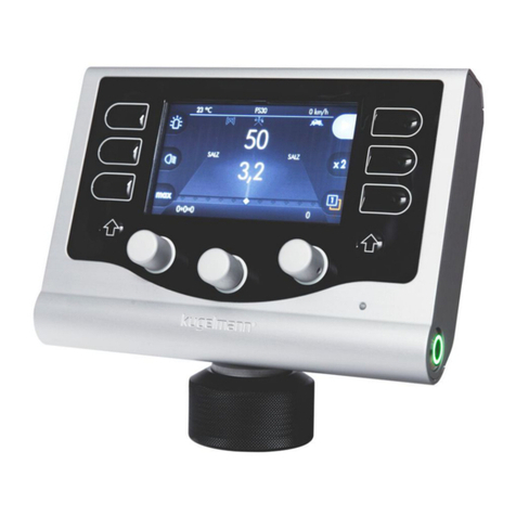
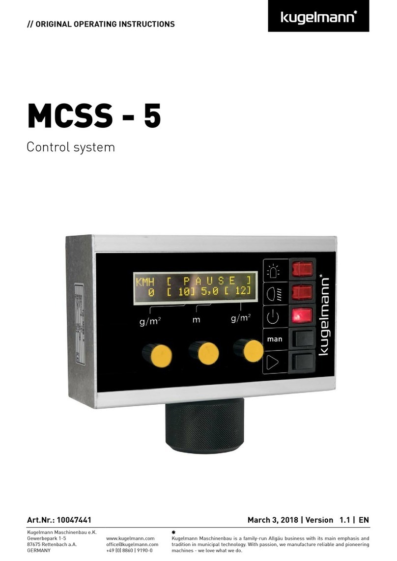
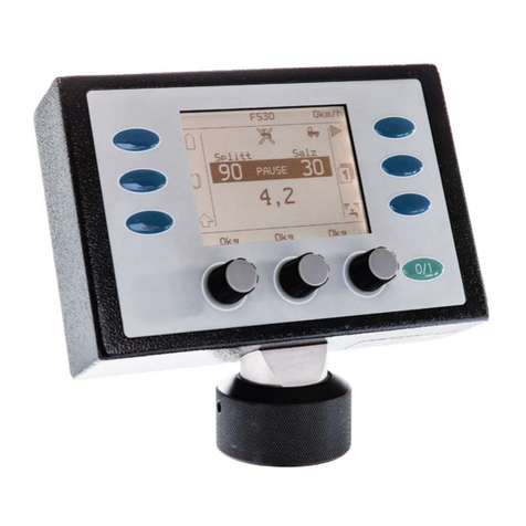
Kugelmann K-TRONIC User manual

// OPERATING INSTRUCTIONS
K-TRONIC
Control system
Art. no. 10044928 28.05.2018| Version 1.1 | EN
Kugelmann Maschinenbau e.K.
Gewerbepark 1-5
87675 Rettenbach a.A.
GERMANY
www.kugelmann.com
+49 (0) 8860 / 9190-0
kugelmann Maschinenbau is a family-run Allgäu business with its main emphasis and
tradition in municipal technology. With passion, we manufacture reliable and
pioneering machines - we love what we do.

Subject to modifications
2 Control system k-tronic
English

Subject to modifications
Table of contents
Control system k-tronic............................................................................... 5
Operating elements of control system k-tronic.............................................................................................6
Display areas of control system k-tronic .......................................................................................................8
Meaning of buttons in operating mode........................................................................................................11
Button 4 for spreading/pause........................................................................................................................12
Output rates.....................................................................................................................................................15
Temperature display ( ) (option) ...............................................................................................................16
Additional functions of left shift key .....................................................................................................17
Differentiation path-dependence
and manual mode ....................................................................................................................................19
Changing between manual mode
and path-dependence ..........................................................................................................................20
Motor unit (option)......................................................................................22
A: Motor unit - petrol......................................................................................................................................22
B: Motor unit - diesel......................................................................................................................................24
Electrical adjustment of spreading pattern (option)..........................................................................................26
Additional function when pressing right shift key
or spreading button...........................................................................................................................................28
Setting of spreading materials for the individual chambers......................................................................30
Spreading units with pre-wetted salt equipment (option)..........................................................................32
Operating instructions 3
www.kugelmann.com
English

Subject to modifications
Output counter (option) .................................................................................................................................34
Electrical spreading control (option)............................................................................................................36
Double dosing (option) ..................................................................................................................................37
User menu...................................................................................................38
Menu operation.................................................................................................................................................39
Soft switch.........................................................................................................................................................39
Setup screens...................................................................................................................................................39
Description of user menu points ..................................................................................................................42
Emptying...........................................................................................................................................................42
Daily statistics...................................................................................................................................................43
Complete statistics............................................................................................................................................43
Simulation speed km/h .....................................................................................................................................44
Key tone ON .....................................................................................................................................................44
Show output counter (option)............................................................................................................................44
Language: D-GB-F-I.........................................................................................................................................45
Working with locked chambers.....................................................................................................................46
Display of errors and warnings.....................................................................................................................48
Display of actual values during spreading operation.................................................................................49
Index .................................................50
4 Control system k-tronic
English

Subject to modifications
The control system k-tronic
The control system for truck-mounted spreaders and three-point spreaders
The control system k-tronic for truck-mounted spreaders and three-point spreaders consists of two major electronic
components, the master and the slave.
The master (Version V4)
The master is the operating unit in the driver’s cab. All settings concerning the spreading operation are made from the
master. The master is installed easily accessible in the driver’s cabin. By means of the plug-and-socket connection, it
can be easily replaced or removed. By means of a permanently installed cable set, the firmly installed socket of the
plug-and-socket connection is connected with the central plug connection behind the driver’s cabin. The length of the
permanently installed cable set is adjusted to the respective vehicle.
The slave (Version V7)
The slave is the switching electronics at the rear of the spreader. The slave controls all hydraulic valves; furthermore,
electric consumers like rotating beacon and working headlights are controlled by the slave.
The electrical supply of the spreader is accomplished by a secured line from the vehicle battery. Together with the
control lines of the master, this supply line is connected with the central plug connection behind the driver’s cabin
and fed to the cable set of the spreader. A cable set is firmly installed at the spreader. After mounting the spreader,
this cable set must only be connected at the central plug connection.
If the master should be replaced, no settings are lost as all data is saved in the slave. Thus, it is possible to continue
working with the saved data immediately also with a different master.
To operate the master, the spreader must be connected with the central plug connection because the
master receives its energy supply and its data via the slave.
Master
Operating instructions 5
www.kugelmann.com
English
Slave

Subject to modifications
Operating elements of control system k-tronic
Button 1
Button 2
Button 3
Button 4
Button 5
Button 6
Button ON
Left
turning
knob
Middle
turning
knob
Right
turning
knob
6 Control system k-tronic
English

Subject to modifications
Button 1 to button 6
Depending on the display, the buttons 1 to 6 trigger different actions. Description on the following pages.
Button ON
-Switches the spreader on and off.
-The function of this button never changes.
When switching off, all drives are stopped and the rotating beacon as well as the working headlight will
be switched off at the control system.
Before the control system is switched on, starting of the vehicle motor is indispensable as the
voltage may drop extremely during the starting procedure. If the control system is already switched
on, in particular vehicles with a board voltage of 12 Volt recognize this as error “low voltage”.
Turning knob left/middle/right
The turning knobs are provided with a detent mechanism.
Turning from one detent to the next produces a control tone. The control tone may be switched off.
The turning knobs may be pressed and receive a different function. If a turning knob must be pressed to change values,
this is specially indicated in the description. A normal change of values is executed in unpressed condition.
Operating instructions 7
www.kugelmann.com
English

Subject to modifications
Display areas of control system k-tronic
Temperature display (option) (Page 16)
Percentage of pre-wetted salt during brine spreading (Option) (Page 32)
Vehicle speed (Page 16)
Rotating beacon on/off (Page 11)
Motor unit on/off (Option)(Page 22, 24)
Electrical spreading control spreading material yes/no (Option) (Page 36)
Brine spreading on/off (Option) (Page 32, 33)
Spreader works path-dependent/in manual mode (Page 20, 21)
Spreader operating/pause (page 12, 13)
8 Control system k-tronic
English

Subject to modifications
Working headlight at spreading disc on/off (Page 11)
Spreading quantity left chamber (Page 15)
Sum of spreading quantities (Page 15)
Spreading quantity right chamber (Page 15)
Spreading width (Page 16)
Operator levels Level1/Level2 (Option) (Page 14)
Left shift key not activated/pressed (Page11, 17)
Electrical adjustment of spreading pattern (option) (Page 26)
Right shift key spreading button (Page 14, 26)
Output counter left chamber (option) (Page 34)
Output counter brine tank (option) (Page 35)
Output counter right chamber (option) (Page 34)
Operating instructions 9
www.kugelmann.com
English

Subject to modifications
10 Control system k-tronic
English

Subject to modifications
Meaning of buttons in operating mode
Button 1 for rotating beacon
Press button 1 to switch on the rotating beacon.
Display changes from to .
Press button 1 again to switch off the rotating beacon. Display changes
from to .
Button 2 for the working headlight
The working headlight is located at the wing of the spreading disc suspension.
Press button 2 to switch on the working headlight.
Display changes from to .
Press button 2 again to switch off the working headlight. Display changes
from to .
Button 3 is the left shift key
Various settings concerning the spreading operation are possible by pressing this
button. To execute the individual actions, hold button 3 pressed.
Display changes from to .
The functions of buttons 1, 2, 4, 5 and 6 as well as the functions of the turning knobs change (see paragraph left shift
key).
By releasing button 3, you exit this special page. Display changes
from to .
Exception: If you press button 6 with button 3 also pressed down, you reach the user menu
(see paragraph user menu).
Operating instructions 11
www.kugelmann.com
English

Subject to modifications
Button 4 for spreading/pause
1.) Start spreading
After switching the spreader on with button ON, the spreader is set to “PAUSE”. To
start spreading, press button 4 .
Display of button 4 changes from to . The black bar behind the spreading quantities will be deleted
and the sum of the spreading quantities will be shown instead of .
Display during spreading
12 Control system k-tronic
English

Subject to modifications
2.) Spreading PAUSE
Press button 4 in order to interrupt spreading for a short time.
Display of button 4 changes from to .
The sum of spreading quantities is replaced by and the spreading densities are marked with a
dark bar.
Display during PAUSE
Operating instructions 13
www.kugelmann.com
English

Subject to modifications
Button 5 is the level button
At the control system k-tronic, you have the possibility to deposit 2 different data sets for the user levels
and .
To change the user levels, press button 5.
Display changes from to , and vice versa.
After switching on (Button ON), user level 1 is always set.
Button 6 is the right shift key
Use the right shift key to set different options concerning spreading operation and spreading materials.
To execute the individual actions, hold button 6 pressed.
The functions of buttons 1, 2, 3, 4 and 5 as well as the functions of the turning knobs change (see paragraph right shift
key). Depending on the options of the spreading unit, the displays of the buttons 1, 2, 3, 4 and 5 get new symbols.
By releasing button 6, you exit this special page. The buttons 1, 2, 3, 4, and 5 as well as the turning knobs receive their
original functions.
14 Control system k-tronic
English

Subject to modifications
Output rates
The output rates indicate the spreading density in grammes per square metre (g/m²) separately for each chamber.
The output rates for the left and right spreading chamber can be set to different values.
If different spreading materials exist in the chambers, it is possible to set any desired mixing ratio of both spreading materials.
The mixing ratio can be adjusted to the respective road conditions at any time, even while driving. As soon as you have
set the appropriate mixing ratio for operation, you can lock the chambers against each other (see paragraph “Locking of
chambers”).
Output rate for left chamber ( )
The output quantity for the left chamber can be set at the left turning knob.
The increments per turning knob detent as well as the upper and lower limit can be set in the menu.
Output rate for right chamber ( )
The output quantity for the right chamber can be set at the right turning knob.
The increments per turning knob detent as well as the upper and lower limit can be set in the menu.
Sum of output quantities ( )
Display of sum of both chambers in grammes per square metre (g/m²). In case of pre-wetted salt equipment, the
proportional weight of brine is included (see paragraph “part of brine”).
Display only during spreading operation. At pause, “PAUSE” is displayed at this point.
When working with locked chambers, the sum of the output quantities is written in large numbers and the output
quantities of the left and right chamber is written in small numbers (see paragraph “Locking of chambers”).
For the output quantities of each spreading material, it is possible to set individual values for minimum, maximum and
step width per turning knob detent.
Operating instructions 15
www.kugelmann.com
English

Subject to modifications
Spreading width ( )
The spreading width is indicated in metres.
Adjustment of spreading width by means of the middle turning knob.
The step width per turning knob detent as well as the upper and lower limit can be set in the menu.
Vehicle speed ( )
The current vehicle speed is displayed. This display is intended for controlling purposes and should indicate the same
speed as the speedometer. At first assembly of the spreader, the speed signal is adjusted to the respective vehicle. The
adjustment of the speed signal is executed by the distributor or the service personnel.
If the spreader is running in manual mode, the simulation speed set here is displayed.
Temperature display ( ) (option)
Displayed only if the temperature sensor is part of the spreader equipment. Displayed in °C.
16 Control system k-tronic
English

Subject to modifications
Additional functions of the left shift key
To execute the additional functions, press button 3 and hold it pressed
-Display of button 3 changes from to .
-The respective button with the displayed function must be pressed additionally.
Depending on the spreader options, additional symbols may be displayed; though, these symbols can not be
influenced by the left shift key. For example, the display may look like this.
The functions of buttons 1, 4 and 6 change with the left shift key pressed.
Button 1:
Stop/start motor unit (Option) (Page 22) Special equipment
Button 4:
Switching between Manual operation
and path-dependence (Page 19)
Operating instructions 17
www.kugelmann.com
English

Subject to modifications
Button 6:
Entry into user menu (Page 34)
Buttons 2 and 5 as well turning knobs are not occupied with the left shift key pressed.
When activating the shift key, nominal values are shown instead of actual values. In addition, the
measured supply voltage 13,1V is displayed in the upper line.
18 Control system k-tronic
English

Subject to modifications
Distinction path-dependence and
manual operation
Path-dependent spreading
The control system k-tronic calculates the quantity of spreading material for the spreading operation on the
basis of the vehicle speed.
Manual operation
During manual operation, the control system k-tronic calculates the quantity of spreading material for the spreading
operation by means of the set simulation speed (independently of the actual vehicle speed).
If you switch to spreading operation by means of button 4, spreading starts with manual operation,
even if the vehicle is standing still.
Operating instructions 19
www.kugelmann.com
English

Subject to modifications
Changing between manual operation
and path-dependence
1.) Switching from path-dependence to manual operation.
The display shows
-Hold button 3 pressed the symbol changes to .
Display changes to
-Press button 4.
Display changes to
-Release button 3.
The display shows
-Press button 4 to start spreading.
Display changes to
From now on, the spreader works in manual mode with the set simulation speed of
The simulation speed can be set in the user menu. (See paragraph “Setting of simulation speed”).
20 Control system k-tronic
English
Other manuals for K-TRONIC
1
Table of contents
Other Kugelmann Control System manuals
Popular Control System manuals by other brands

Triangle MicroSystems
Triangle MicroSystems PETROSMART EZ installation instructions

Woodward
Woodward SYNCONpanel Brief manual

Evil Mad Scientist
Evil Mad Scientist Ostrich Eggbot 2.0 Assembly guide

Monitech
Monitech ML121QT1400 install guide

Mitsubishi Electric
Mitsubishi Electric E70 Series instruction manual

Garmin
Garmin G1000 Series pilot's guide