Kugelmann K-TRONIC User manual

// DETAILS MENU
K-TRONIC
Control system
Art. no. 10028913 07.12.2016 | Version 1.3 | EN
Kugelmann Maschinenbau e.K.
Gewerbepark 1-5
87675 Rettenbach a.A.
GERMANY
www.kugelmann.com
offic[email protected]
+49 (0) 8860 / 9190-0
kugelmann Maschinenbau is a family-run Allgäu business with its main emphasis and
tradition in municipal technology. With passion, we manufacture reliable and
pioneering machines - we love what we do.

Subject to modifications
2 Control system k-tronic
English

Subject to modifications
Table of contents
Explanations .....................................................................................................................................................7
The details menu ......................................................................................... 9
Content of details menu.................................................................................................................................10
Error list...........................................................................................................................................................12
Speed signal....................................................................................................................................................13
Sensor adjustment .........................................................................................................................................15
Regulator adjustment.................................................................................16
Parameters ......................................................................................................................................................16
Teach-in...........................................................................................................................................................16
Characteristic curve .......................................................................................................................................17
Error delay.......................................................................................................................................................17
Adjustment of spreading image ................................................................18
Current limit.....................................................................................................................................................18
Mechanical limits............................................................................................................................................18
Working range.................................................................................................................................................19
Movement during emptying...........................................................................................................................19
Spreading materials ...................................................................................20
Details menu 3
www.kugelmann.com
English

Subject to modifications
Spreading material menu...............................................................................................................................20
Output counter................................................................................................................................................22
Display increments.........................................................................................................................................23
Spreading width..........................................................................................24
Setup screen: display increments ................................................................................................................24
Sub-menu item: spreading width..................................................................................................................25
Options........................................................................................................26
Temperature display.......................................................................................................................................26
Display km/h....................................................................................................................................................26
Approval of output counter ...........................................................................................................................26
Motor unit ........................................................................................................................................................26
Brine equipment .............................................................................................................................................28
Adjustment of spreading pattern..................................................................................................................28
Disc stop - pause............................................................................................................................................28
Disc stop at stop.............................................................................................................................................29
Spreader stop at km/h....................................................................................................................................29
Supplementary level...................................................................................30
Sub-menu item: Button MAX.........................................................................................................................30
Sub-menu item: Button X2.............................................................................................................................31
Sub-menu item: Level 2 .................................................................................................................................31
Spreading control...........................................................................................................................................32
4 Control system k-tronic
English

Subject to modifications
Protocol ...........................................................................................................................................................33
Speed reporting ..............................................................................................................................................34
Standstill message .........................................................................................................................................34
Input functions............................................................................................35
Activation of input functions.........................................................................................................................35
Assignment of a function to an activated input ..........................................................................................35
Functions of inputs ........................................................................................................................................35
Reaching spreading image positions via function keys ............................................................................37
Rotating beacon at board net........................................................................................................................39
Working headlight at board net.....................................................................................................................39
Display of spreading material........................................................................................................................39
Automatic locking...........................................................................................................................................40
Chamber partition wall...................................................................................................................................40
Double dosage................................................................................................................................................40
Details menu 5
www.kugelmann.com
English

Subject to modifications
6 Control system k-tronic
English

Subject to modifications
Explanations
User interface
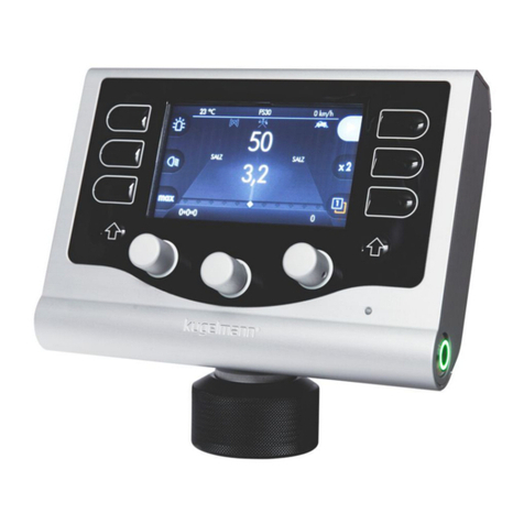
Display appearing after switching on the control system k-tronic.
Turning knob
The control system k-tronic disposes of 3 turning knobs in the lower area. The turning knobs have no
internal/mechanical stop, they can be rotated continuously.
In addition, the turning knobs feature a push-button function. To actuate this button, the turning knob must be pressed
in the direction of the rotation axis.
The turning knobs have partly different functions within the different menu options. During turning the turning knob,
the value of the setup screens changes at the last digit. At many setup screens, the values can be modified with the
turning knob pressed; the setting value changes by factor 100 per detent.
At particular setup screens, the push-button of the turning knob triggers actions.
Button 1 to button 6
The control system k-tronic has 6 buttons.
The buttons have partly different functions within the different menu options. If a
button with a small symbol is displayed (e.g. button ), the button closest to the displayed symbol is
meant.
In certain cases, a different button must be pressed for a function (e.g. right and left shift key).
Button ON
The button ON at the control system k-tronic switches on and off the supply voltage of the spreader.
When switching on by means of the ON button, the spreader always starts at level 1 with operating mode .
The spreader starts also at level 1 even if the control system has been switched off at level 2.
When switching off by means of the ON button, all drive units will be stopped and all connected consumers
will be switched off.
Details menu 7
www.kugelmann.com
English

Subject to modifications
Menu
A menu consists of one or several menu lines. A further menu or a setup screen can be attached to a menu line.
Depending on the equipment of the spreader, individual menus may feature a lower number of menu items as
described here.
Go to a subjacent menu or setup screen by means of button 6 .
Leave the menu or screen by means of button 4.
Choose menu line
Skip from one menu line to the next by turning the left turning knob . The menu line
highlighted in dark color is selected. By turning the turning knob clockwise, the menu line below will be selected; by
turning anti-clockwise, the menu line above will be selected. If a menu consists of more than 5 menu points, the whole
menu will be built up on several pages. It is possible to browse within the menu in blocks of a maximum of 5 pages. To
control where you are currently navigating, a small rectangle is shown on the right side that moves up or down
depending on the menu line.
Soft switch
There are menu lines offering a 0/1 possibility to select. In such cases, the respective menu line is equipped with a so-
called soft switch. The setting is limited to “ON” ( ) or “OFF” ( ). The current switching status of the soft
switch is displayed in the respective menu line for review. With the menu line selected, the alternative switching
status is displayed at button 5.
Setup screen
A setup screen may be attached to the menu line. A setup screen is split into three columns, whereby values must not
be stored in all three columns. Always use the turning knob below to change values within a column. The modified
values of the setup screens are adopted and stored immediately.
With a menu line selected, go to the setup screen by means of button 6 .
Use button 4 to leave the setup screen.
If a large value range can be set in a column of the setup screen, the value may be changed by
factor 100 per detent by turning the pressed turning knob.
8 Control system k-tronic
English

Subject to modifications
The details menu
During the first assembly of the spreader onto the carrier vehicle, settings, which are necessary for the correct
operation of the spreader, are made in the details menu. Also the individual options of the spreader are selected and
deselected here.
Find the details menu as follows
For safety reasons, the spreader must be in operating mode before entering the user
menu.
Keep the left shift key pressed.
Press the button 6 for a short time to go back to the user menu.
Now, release button 3.
Choose the line “Details menu” by means of the left turning knob , the line will be highlighted in
dark color. Then, press button 6 .
You are now prompted to enter the access code.
The same screen also shows the current software version of master and slave. The access code for the
details menu is calculated as follows:
999 + 3 times master version - 1 time slave version
z.B .: With master version number 2 and slave version number 4 you have to set 999 + 3x2 - 1x4 = 1001 by means
of the middle turning knob.
Use button 6 to go to the details menu.
Details menu 9
www.kugelmann.com
English

Subject to modifications
Contents of details menu
Error list
Display of last errors with a frequency counter.
Warning list
Display of last warnings with a frequency counter.
Speed signal
Adjustment of spreader to the speed signal of the carrier vehicle.
Sensor adjustment
Setting of sensors at the individual drives of the spreader.
Regulator adjustment
Presetting of regulation parameters for the operation of the spreader.
Adjustment of spreading image
Only for spreaders with electrical adjustment of the spreading pattern. The values for the electrical adjustment of the
spreading pattern are set here.
Spreading materials
Setting of pulses per kilogram for the left and right screw at the corresponding spreading materials.
10 Control system k-tronic
English

Subject to modifications
Spreading width
Setting of spreading width at the mounted spreading disc.
Options
Possibility to carry out additional settings for operation.
Depending on the equipment of the spreader, it is also possible that less menu points are available in
this menu. For example, the menu point “adjustment of spreading pattern” is not available at all
spreaders.
Details menu 11
www.kugelmann.com
English

Subject to modifications
Error list
Up to 15 errors with frequency and order of appearance may be displayed in the error list. The latest error is
displayed on top of the list.
Frequency counter
If the same error occurs several times, the frequency counter is increased at each occurrence of the error. As soon as
another error occurs, the list will be extended by a new entry.
The display may be deleted by button 1. This means that errors which have occurred before deletion of the display
can no longer be shown by means of the control system. If no new errors occur until the next selection of the error
list, an empty list will be displayed.
Use button 4 to leave the error list - no entries will be deleted. If more than 15 errors have occurred in
different order, the older errors can no longer be displayed by the control system.
Warning list
Up to 15 warnings with frequency and order of appearance may be displayed in the warning list. The latest
warning is displayed on top of the list.
Frequency counter
If the same warning occurs several times, the frequency counter is increased at each occurrence of the warning. As soon
as another warning occurs, the list will be extended by a new warning.
Use button 1 to delete the warning display. This means that warnings which have occurred before deletion of the
display can no longer be shown by means of the control system. If no new warnings occur until the next selection of the
warning list, an empty list will be displayed.
Use button 4 to leave the warning list - no entries will be deleted. If more than 15 warnings have occurred
in different order, the older warnings can no longer be displayed by the control system.
If no new warnings have occurred since the last reset of the warning list, an empty list will be displayed.
12 Control system k-tronic
English

// DETAILS MENU
Error and warning list
Error Designation Possible cause Troubleshooting
1
Vehicle voltage
too low
•
The supply voltage was or is below
10.0
V, e.g. because of starter of short
circuit in the electrical system
–
Elimination of cause for the
voltage drop
–
Confirm the error message
by activating the pause
button
2
Unit off
•
The oil unit has been switched off
manually
•
The unit has run out of fuel (tank
empty)
–
Eliminate cause for
standstill
–
Restart unit
3 Error reversing
•
reversed - reversed
4 Sensor disc defective
•
The sensor does not recognize a
change
•
No oil supply for spreader
•
Drive jammed or stuck
•
Sensor incorrectly set
–
Eliminate blockades or
false positions
–
Ensure oil supply
–
Set sensors correctly
5
Right sensor
defective
6
Left sensor defective
7
Sensor brine
pump defective
8 Undersupply
screws
•
The spreading quantity can not be
reached with the current oil capacity
•
Oil capacity too low
•
Speed too high
•
Characteristic curve wrong
–
Reduce speed
–
Correct characteristic curve
9
Undersupply disc
10
Undersupply
brine pump
11
Oversupply
brine pump
•
The current quantity of spread
material is much too high
•
Handwheel open
•
Characteristic curve wrong
–
Close handwheel
–
Correct characteristic curve
12 Oversupply
right side
13
Oversupply left side
14
Oversupply disc
15
Setting motor
blocked
•
Setting motor oxidized
•
Settings min/max wrong
•
Disc unit bent
–
Clean setting motor, make
it running again or replace
it
–
Correct settings
–
Adjust or replace disc
unit
16 Pause because of
chute
17
Error thermography
•
Connection to sensor defective
•
No thermography connected
–
Check socket connections
and cables
–
Connect sensor or select
in menu
Error and warning list

// DETAILS MENU
Warning
Designation
Possible cause
Eliminate warning
1
Unit does not
start
•
Unit - battery empty
•
Ignition not switched on
•
Fuel tank of unit empty
– with Pause button
2 Unit does not stop
•
Cable break/short-circuit – with Pause button
3 Dry run brine
pump
•
Brine reservoir empty
•
Sensor dry run maladjusted
–
Fill brine reservoir
–
Confirm with Pause button
4
Electrical monitoring
of spreading process
•
no spreading material left in spreader
•
Electrical monitoring of spreading
process incorrectly set
•
Incorrect position of sensor flag
–
Refill spreading material
–
Set or readjust sensor
5
Pause because of
chute
•
Chute standstill or folded up in
manual mode
•
Vehicle voltage below operating
voltage for sensor
–
Fold down chute
–
Sensor control chute
–
Control vehicle voltage
6
Unit tank nearly
empty
•
Fuel tank nearly empty – Fill up fuel
7
Unit error
•
Generator does not operate correctly
•
Pressure switch motor oil responding
•
Overtemperature motor
•
General error motor
– carry out maintenance of
motor (see instructions)
8 Unit - hydraulic oil
empty
•
Hydraulic oil sensor responding – fill up hydraulic oil or
control sensor
Error and warning list

Subject to modifications
Speed signal
In order to guarantee correct operation of the spreader with path dependence, the speed signal of the spreader must
be adjusted to the respective vehicle. You have three different entry possibilities:
-Teach-in
-manual entry
-via distance
Teach-in
Teach-in is a simple method to adjust the speed signal to the respective vehicle. Drive the vehicle with one of the two
preset speeds (15 km/h or 30 km/h) and press the turning knob with the respective indication “Teach-in 15 km/h “ or
“Teach-in 30 km/h”. The value for the speed signal will be determined and saved for displaying the speed at the
control system k-tronic.
For controlling purposes, the current speed is displayed in the upper right corner. The display is calculated via the
value which is stored in the control system for impulses per driven meters.
The impulses per driven meter currently stored in the control system are displayed in the middle column. In case of
minor deviations between the display at the control system k-tronic and the speedometer, the value for the impulses
per driven meter can be corrected by means of the middle turning knob. When exiting the setup screen by means of
button 4
, the last value displayed is maintained for the calculation of the speed display and thus for the calculation of
path dependence.
In case of minor deviations between the display at the control system k-tronic and the speedometer, you can of course
press the respective turning knob anew as soon as the indicated speed of 15 km/h or 30 km/h has been reached. This
can be repeated until the result is satisfactory. When exiting the setup screen, the last determined value for the speed
signal is saved and will be used for the operation of the spreader in case of path-dependence.
Manual entry (speed signal)
In many cases, the value for the speed signal is indicated in the instruction manual of the vehicle on which the
spreader is mounted. If the value for the speed signal of your carrier vehicle is known, you can directly set this value
in the setup screen “manual entry”.
Setting range: 0.50 to 650.00 impulses/meter
If your vehicle supplies a higher value than 650 impulses per meter, please interpose our speed signal divider. By
means of this signal divider, the speed signal from the vehicle is divided down by the factor 10 and fed to the control
system k-tronic. Thus, values up to 6500.0 impulses per driven meter may be recorded.
Details menu 13
www.kugelmann.com
English

Subject to modifications
Via distance
You can also determine the speed signal for the spreader via an exactly calculated distance. You drive up to the starting
point of the measuring distance, press the start button, cover the measuring distance directly without stopping and press
the stop button at the end. All impulses between pressing the start and stop button are counted and calculated together
with the entered distance.
It is important to cover the distance directly, each change of direction leads to a wrong measuring
result.
If there is a deviation between the speed signal at the vehicle and the display at the control system
k-tronic, this may have different causes:
- change of direction during driving the measuring distance
- start or end point not exactly reached
- worn tyres of vehicle
- driving with snow chains etc.
14 Control system k-tronic
English

Subject to modifications
Sensor adjustment
The sensors of the individual drives are set at the manufacturer's works. If, contrary to expectations, a sensor does
not function, the function of the individual sensors can be controlled at this setup screen. If a defective sensor has
been replaced, the new sensor is set to the correct distance with respect to the sensor disc or the motor shaft by
means of this setup screen.
To move the respective drive, the hydraulic system has to be switched on; then, you press the middle turning knob.
At the lower right corner, 2 small numbers appear.
The upper number indicates the current distance from the sensor to the punched disc or motor disc. If the individual
values are smaller than 70, this can lead to a failure during teach-in of the regulator adjustment. In case of values
above 210, the sensor may be destroyed.
The lower number shows the identified impulses. If this number does not change, the sensor may be too far away,
connected incorrectly, the sensor line may be interrupted or the sensor may be defective.
It is important to carry out the setting of the spreading disc sensors and the brine pump with greatest caution, because it
is not possible to see the distance between sensor and the toothed shaft. It is recommended to turn in the sensor only in
small steps and check at regular intervals in between. If the sensor is advanced too far at the beginning, it may be
destroyed by the turning shaft.
Details menu 15
www.kugelmann.com
English

Subject to modifications
Regulator adjustment
The control system k-tronic determines own regulator parameters for each hydraulic drive. These regulator parameters
are necessary so that the drive units reach the correct speeds after a spreading pause or a change of settings.
The basic setting of the individual regulators must be carried out at each spreader with the corresponding
hydraulic oil supply.
Parameters
At the control system k-tronic, one set of parameters is part of each hydraulic drive. These 2 parameters are necessary
for the control behavior of the relevant drives. These parameters are determined by means of numerous tests and must
usually not be corrected. The damping stands for the reaction time of the regulation and the ramp stands for the
amount of change.
If a drive should overshoot or undershoot in case other values are regulated, it is wrong to increase
damping in order to faster reach a value. Overshoot or undershoot may only be avoided by reducing
the values.
Teach-in
To reach a correct working result of the spreader, a teach-in of the individual hydraulic motors of the drives is
necessary during first assembly of the spreading unit. This is done via teach-in.
Observe the following rules for teach-in:
-The sensors must be set exactly
-The hydraulic unit must supply a sufficient quantity of oil. Set the vehicle speed to the upper limit of the
green area.
-The speed must be constant during the whole teach-in procedure.
Tip button 1 to start the teach-in. The drive starts to rotate slowly and is getting faster until the
maximum speed has been reached. This procedure is run through 2 times. In case of danger, it can
be stopped by pressing button 4.
16 Control system k-tronic
English

Subject to modifications
The progress of teach-in is displayed at the appearing bar. At the end of the teach-in, values are
shown and the result whether the attempt was successful or not.
If the teach-in has failed, it has to be determined by means of the displayed values why the error has occurred.
The determined values for 0 to 10 must be in ascending order. If one value is higher than the value that follows,
the teach-in has to be carried out once again because there may be some air bubbles left in the oil circuit.
If several values are out of sequence, the sensor of the respective drive should be checked once again. During sensor
adjustment, no single value of the smaller number must be below 70!
If a value above 1900 exists for one parameter, all values are rejected although a uniform increase of values would be
present. Maybe the oil supply has collapsed or the speed was not constant until the end.
If 0 is present at value “0”, this may mean that the drive rotates without external intervention. Check whether the
handwheels at the hydraulic block are closed, start teach-in again.
Characteristic curve
Caution! In this setup screen, wrong operation may cause the greatest damage. Incorrect operation
may lead to maladjustment of the characteristic curves, this means that the drives may turn very
slowly or not at all. Incorrect operation may also lead to the setting of a characteristic curve which is
not “OK”.
In this setup screen, the desired parameter is set at the left side: 0 - 10
In the middle, the numerical value for the parameter set at the left side is displayed: 0.00 to 20.00 W
At the right column, the determined frequency for this drive is displayed: 0.00 to 300.00 Hz
Error delay
As a continuing oil flow can not be guaranteed at some oil supply systems, e.g. in case of PTO pumps, the individual
errors can be delayed in such cases. For example, the delay of speed monitoring (sensor defective) can be delayed for
the period of one switching operation.
Delayable:
-Oversupply (0 - 25.0 seconds)
-Sensor defective (0 - 25.0 seconds)
-Undersupply (0 - 25.0 seconds)
Details menu 17
www.kugelmann.com
English

Subject to modifications
Adjustment of spreading image
Only for spreaders with “Electrical adjustment of spreading pattern”.
Increased danger of contusions. During the adjustment of the spreading pattern, do not reach into
the displacement range of the spreading disc suspension.
Setting ranges of the spreading image values: from 0 to 255
MINIMUM: from 0 to “working range - LEFT”
LEFT: from “mechanical limits - MINIMUM” to “Working range - CENTER”
CENTER: from “working range - LEFT” to “Working range - RIGHT”
RIGHT: from “Working range - CENTER” to “mechanical limits - MAXIMUM”
MAXIMUM: from “working range - RIGHT” to 255
Current limit
The motor current is monitored to recognize blocking of the servo motor. As the motors may have different sizes, the
current limit for the respective motor size has to be set here.
Example: Linak Type 121P00 -> 1.8 ampere or,
Linak Type M301P1 -> 4.0 ampere
Mechanical limits
The mechanical limits are determined during first commissioning of the spreader and indicate the maximum
displacement travel of the electrical adjustment of the spreading pattern. These settings are made at the manufacturer's
works. If the motor should be replaced, these mechanical limits have to be determined again.
If a new value is entered in the setup screen for min. or max., this new value will be reached immediately. For
controlling purposes, a small number appears at the center of the display showing where the servo motor is located at
the moment.
If, in a column, the value cannot be modified in a certain direction, this is limited by the setting ranges mentioned
above.
If the motor should block, an error tone will sound and the control number at the center does not change anymore. If the
error tone sounds when setting the minimum limit, the value for minimal must be set slightly higher than the displayed
control number. Example: If the control number remains at 23, the value for MIN. is set to 25.
When setting the maximum limit, the value for MAX. must be set slightly lower than the reached control number.
18 Control system k-tronic
English
Other manuals for K-TRONIC
1
Table of contents
Other Kugelmann Control System manuals
Popular Control System manuals by other brands

Rain Bird
Rain Bird IQ v2.0 instructions

Pilz
Pilz PSSuniversal multi PSSu H m F DPsafe SN SD operating manual

Arrows Hobby
Arrows Hobby Vector manual

Siemens
Siemens SIMOTION Function manual

Efka
Efka euramot AB60D1472 instruction manual

PLC Electronic Solutions
PLC Electronic Solutions HEDEN YMER 3 Operator's guide