LG PRVC1 User manual

P/NO : MFL42540226
www.lg.com
INSTALLATION MANUAL
• Please read this installation manual completely before installing the product.
• Installation work must be performed in accordance with the national wiring
standards by authorized personnel only.
• Please retain this installation manual for future reference after reading it
thoroughly.
MODEL : PRVC1
Low Ambient Control Kit

Low Ambient Control Kit Installation manual
TABLE OF CONTENTS
■Safety Precautions................................................................................3
■Accessory Parts ....................................................................................5
■Name of each part ................................................................................6
■Installation Method................................................................................7
1. Single unit install Guide....................................................................7
2. Series unit install Guide..................................................................11
3. Unit Placement and Clearances.....................................................15
■Setting and using method ...................................................................17
1. Power source input.........................................................................17
2. Wiring for Low Ambient Control PCB and transformer...................19
3. Wiring for Damper Actuator............................................................20
4. Setting of ‘SWDIP’..........................................................................21
5. Setting of outdoor unit dip switch ..................................................22
2Low Ambient Control Kit
■During installation
Safety Precautions
To prevent injury to the user or other people and property damage, the following instructions
must be followed.
■Incorrect operation due to ignoring instruction will cause harm or damage. The seriousness is
classified by the following indications.
■Meanings of symbols used in this manual are as shown below.
WARNING
CAUTION
This symbol indicates the possibility of death or serious injury.
This symbol indicates the possibility of injury or damage.
Be sure not to do.
Be sure to follow the instruction.
WARNING
Installation manual 3
Safety Precautions
Please install the
designated location in the
Control box.
• It can cause the breakdown
or accident.
Do not touch the board
when the power is
connected .
•
It can cause a fire, electric
shock, explosion, injury and
problem to the product.
Always request for
installation of the product to
the service center or the
installation service provider.
•
It can cause a fire, electric
shock, explosion and injury.
When reinstalling the previously
installed product, request for service to
the service center or the installation
service provider.
•
It can cause a fire, electric shock, explosion and
injury.

■During use
4Low Ambient Control Kit
Safety Precautions
Do not modify or extend the
power cord.
• It can cause a fire and
electric shock.
Do not pour water inside the
product.
• It can cause an electric
shock and problem to the
product.
When the product is submersed
in water, always request for
service to the service center or
the installation service provider.
• It can cause a fire and
electric shock.
Make the children and the
elderly use the product with
the help of a guardian.
• It can cause a safety
accident and problems to
the product.
Do not give impact to the
product.
• It can cause problem to the
product.

Installation manual 5
Accessory Parts
Accessory Parts
Cable Assy Terminal Block Assy
Tie (2EA)
Low Ambient Control PCB Transformer
Screw (6EA)
Panel 1EA
Name of each part
6Low Ambient Control Kit
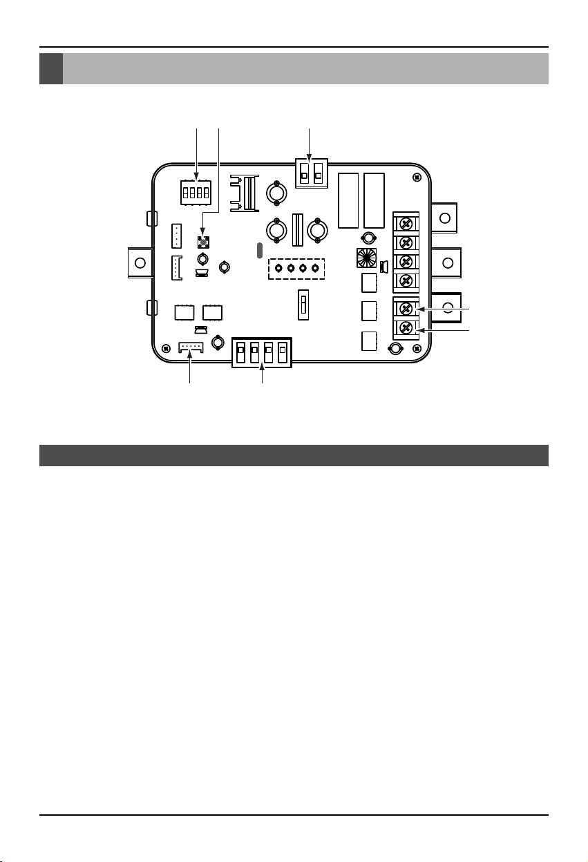
1. CN_PWR : Power input terminal(DC 12V)
2. CN_AO : Signal output terminal to control a damper actuator
3. CN_OUT : Outdoor unit connector
4. BUS_A : RS-485 (+) terminal
5. BUS_B : RS-485 (-) terminal
6. SWDIP : Switch to select main function
7. SW1 : Reset switch
Low Ambient Control Kit
16 7
3 2
4
5
Name of each part

Installation manual 7
Installation Method
1. Shut off the main power line of outdoor unit.
2. Install the LAC(Low Ambient Control) PCB in the control box by using screws.
3. Install the panel assy in the control box by using screws.
4. Connect the Main PCB(CN41) to LAC(CN_OUT) by using the cable assy.
5. Connect the blue wire of transformer to the Main PCB (JIG1(L), JIG2(N)).
1. Single unit install Guide
Installation Method
LAC PCB
Step 2 Step 3
Terminal block
Transformer
Panel
Step 4 Step 5
CN41
CN_OUT
GND
JIG1(L) JIG2(N)

Installation Method
8Low Ambient Control Kit
6. Connect the red wire of transformer to the terminal block (2Pin yellow terminal block).
7. Connect a power cable (DC 12V) to CN_PWR (12V, GND) of LAC
8. Connect the common wire of Damper Actuator to the terminal block and connect the wire of
LAC(CN_AO(GND(A-)) to the common wire of Damper Actuator.
9. Connect the wire of AC 24V of Damper Actuator to the terminal block
Step 6 Step 7
GND 12V
CN_PWR
Step 8 Step 9
AC 24V Power
for Damper Actuator
of Master
GND
Common
AC 24V Power
for Damper Actuator
of Master
AC 24V
GND
Common

Installation Method
Installation manual 9
10. Connect the wire of control signal of Damper Actuator to CN_AO(AO_01(A+)) of LAC
11. Set up the main function dip switch of LAC PCB.
12. Set up the dip switch of MAIN outdoor unit PCB.
13. Using the clamp and tie provided securely attach the wire as shown in the figure.
Step 10 Step 11
ON
1234
AC 24V Power
for Damper Actuator
of Master
DC 0~10V Control Signal
for Damper Actuator
of Master
Master(AO_01(A+))
Step 12 Step 13
ON
SW01B SW02B
1234567
ON
1234567

10 Low Ambient Control Kit
14. Turn on the main power line of outdoor unit.
15. Check the signal to CN_AO(AO_01, GND) of LAC and Air Damper.
Step 14,15
Table of contents
Other LG Control Unit manuals


Popular Control Unit manuals by other brands

Festo
Festo Compact Performance CP-FB6-E Brief description

Elo TouchSystems
Elo TouchSystems DMS-SA19P-EXTME Quick installation guide

JS Automation
JS Automation MPC3034A user manual

JAUDT
JAUDT SW GII 6406 Series Translation of the original operating instructions

Spektrum
Spektrum Air Module System manual

BOC Edwards
BOC Edwards Q Series instruction manual

KHADAS
KHADAS BT Magic quick start

Etherma
Etherma eNEXHO-IL Assembly and operating instructions

PMFoundations
PMFoundations Attenuverter Assembly guide

GEA
GEA VARIVENT Operating instruction

Walther Systemtechnik
Walther Systemtechnik VMS-05 Assembly instructions

Altronix
Altronix LINQ8PD Installation and programming manual


