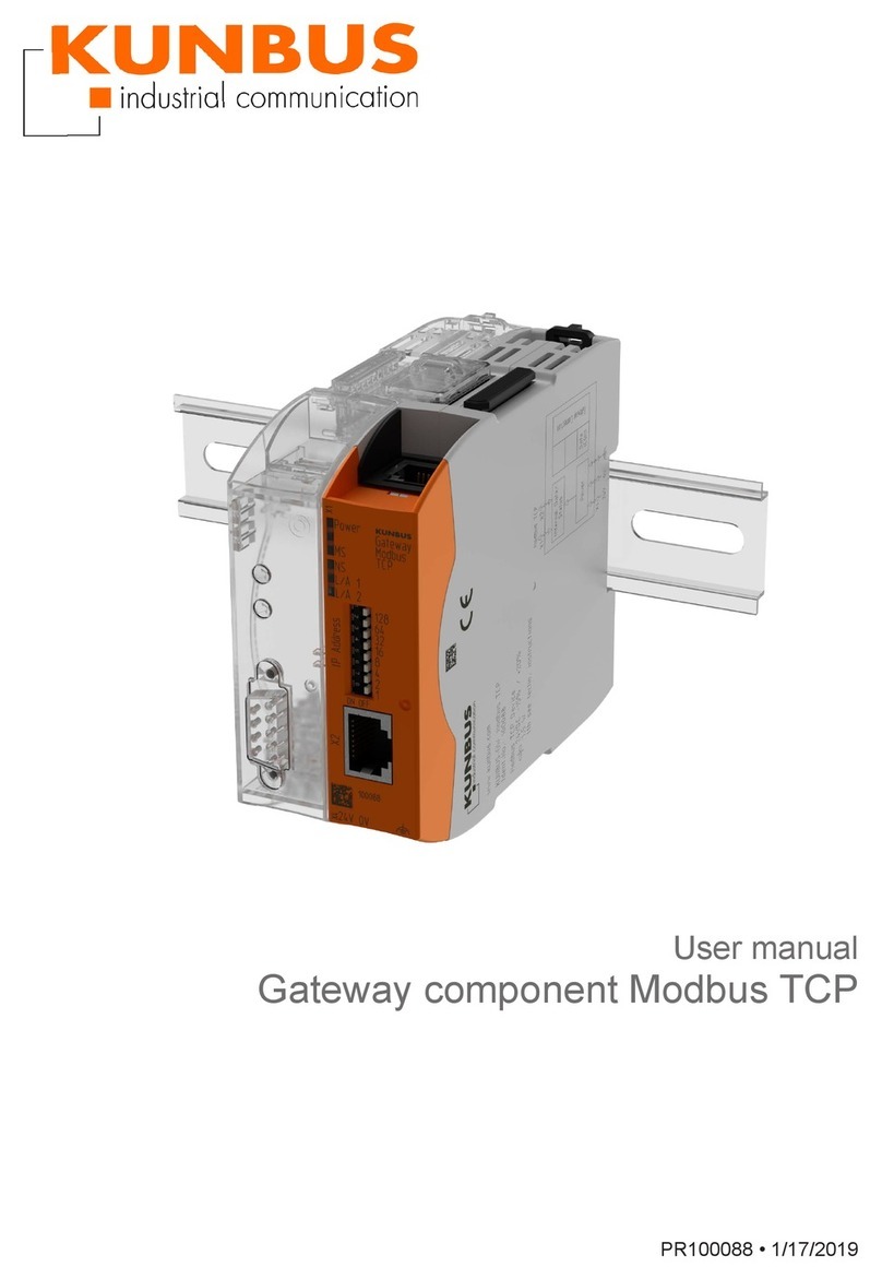
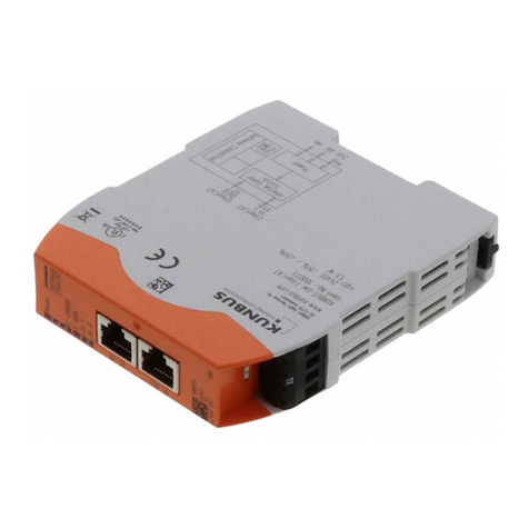
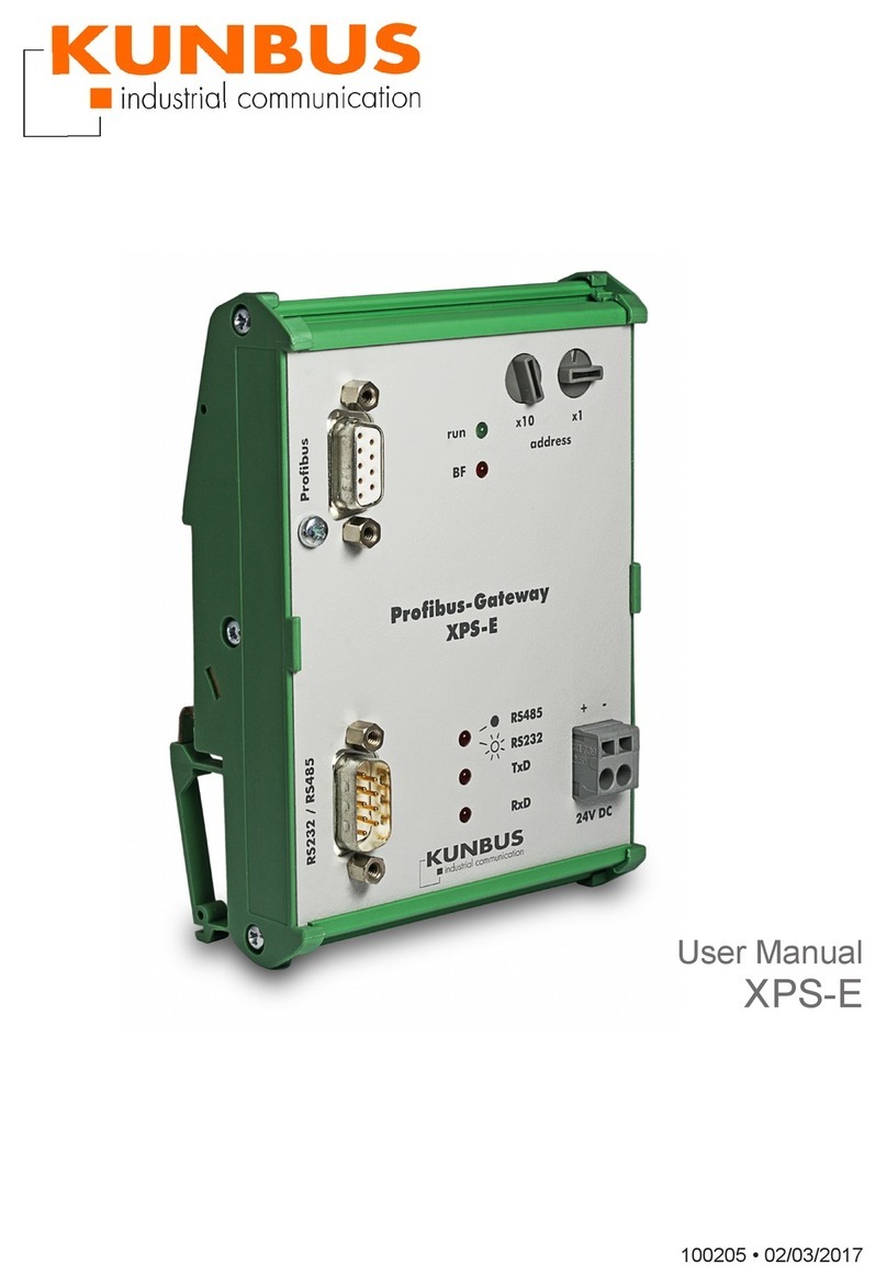
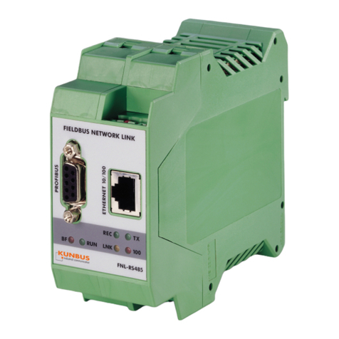
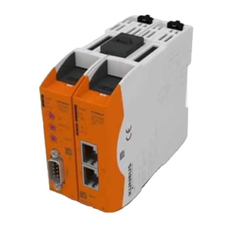
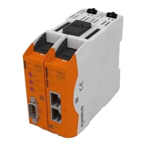
Kunbus FNL Series User manual

User Manual
KUNBUS-FNL
PR1011081 • 25/04/2016

Table of content KUNBUS GmbH
ii FNL
Table of content
1 Working with FNL............................................................................................................................3
1.1 Disclaimer..................................................................................................................................3
1.2 User ...........................................................................................................................................4
1.3 Symbols.....................................................................................................................................4
1.4 Safe Use....................................................................................................................................5
1.5 Limitation of Liability ..................................................................................................................5
1.6 Customer Service ......................................................................................................................6
2 Overview ..........................................................................................................................................7
2.1 FNL............................................................................................................................................7
2.2 PROFIBUS DP ..........................................................................................................................8
2.3 PROFIBUS PA ..........................................................................................................................9
3 Install..............................................................................................................................................10
3.1 Assembly .................................................................................................................................10
3.2 Connect Power Supply ............................................................................................................11
3.3 Connect Ethernet ....................................................................................................................12
3.4 Connect PROFIBUS DP RS485 .............................................................................................13
3.5 Connect PROFIBUS PA .........................................................................................................14
3.6 Connect Service Interface .......................................................................................................16
4 Signals and fault indication .........................................................................................................17
4.1 LEDs........................................................................................................................................17
5 Configure FNL ..............................................................................................................................18
5.1 Software Installalation .............................................................................................................18
5.2 Configure FNL ........................................................................................................................19
6 Disposal .........................................................................................................................................29
6.1 Dismantling..............................................................................................................................29
6.2 Disposal...................................................................................................................................29
7 Technical Data...............................................................................................................................30
7.1 Technical Data.........................................................................................................................30

FNL 3 / 31
1 Working with FNL
1.1 Disclaimer
© 2016 KUNBUS GmbH, Denkendorf (Deutschland)
The contents of this user manual have been prepared by the
KUNBUS GmbH with the utmost care. Due to the technical
development, the KUNBUS GmbH reserves the right to change or
replace the contents of this user manual without prior notice. You can
always obtain the latest version of the user manual at our homepage:
www.kunbus.de
The KUNBUS GmbH shall be liable exclusively to the extent
specified in General Terms and Conditions (www.kunbus.de/
agb.html).
The contents published in this user manual are protected by
copyright. Any reproduction or use for the in-house requirements of
the user is permitted. Reproduction or use for other purposes are not
permitted without the express, written consent of the KUNBUS
GmbH. Contraventions shall result in compensation for damages.
Trademark protection
– KUNBUS is a registered trademark of the KUNBUS GmbH
– Windows® and Microsoft® are registered trademarks of the Microsoft,
Corp.
– Modbus is a registered trademark of the Modbus-IDA Organization.
– EtherCAT® ist eine eingetragene Marke und patentierte Technologie
lizenziert durch die Beckhoff Automation GmbH, Deutschland.
– Sercos is a registered trademark of Sercos International e. V
KUNBUS GmbH
Heerweg 15 C
73770 Denkendorf
Germany
www.kunbus.de
Working with FNL

FNL 4 / 31
1.2 User
The Gateway may only be assembled, installed and put into
operation by trained, qualified personnel. Before assembly, it is
absolutely essential that this documentation has been read carefully
and understood. Expertise in the following fields is assumed:
– Electronic circuits,
– Basic knowledge of PROFIBUS,
– work in electrostatic protected areas,
– Locally applicable rules and regulations for occupational safety.
1.3 Symbols
The symbols used have the following meaning:
DANGER Hazard
Observe this information without fail!
There is a safety hazard that can lead to serious injuries and death.
WARNING Caution
There is a safety hazard that can result in minor injuries and material
damage.
NOTICE Note
There is a safety hazard that can result in material damage.
Working with FNL

FNL 5 / 31
1.4 Safe Use
WARNING Damage and serious personal injury due wrong power supply
FNL is designed exclusively for PELV operation according to EN 60950 /
EN 60204 / VDE 0805-1
èOnly protective extra-low voltages according to the defined standards
may be used to supply and connect the alarm contact.
NOTICE Electrostatic discharge
The device contains components that can be damaged or destroyed by
electrostatic discharge
èWhen handling the device, observe thenecessary safety precautions
against electrostatic discharge (ESD), in accordance with EN 61340-5-1
and EN 61340-5-2, as well asIEC 61340-5-1 and IEC 61340-5-2.
NOTICE Shielding
The shielding ground of the connected twisted pair cables is electrically
connected to the female connector.
èWhen connecting network segments, avoid ground loops, potential
transfers, and voltage equalization currents via the braided shield.
NOTICE Damage due to subsequent processing
Avoid subsequent processing of the FNL.
ØSoldering can cause components to become detached and thus
damage or destroy the module.
ØPlease note that the warranty shall become invalid if the products are
changed technically.
èSpeak to your contact person at the KUNBUS GmbH about customised
solutions.
1.5 Limitation of Liability
Warranty and liability claims will lapse if:
– the product has been used incorrectly,
– damage is due to non-observance of the operating manual,
– damage is caused by inadequately qualified personnel,
– damage is caused by technical modification to the product (e.g.
soldering).
Working with FNL

FNL 6 / 31
1.6 Customer Service
If you have any questions or suggestions concerning this product,
please do not hesitate to contact us:
KUNBUS GmbH
Heerweg 15 C
73770 Denkendorf
Germany
+49 (0)711 3409 7077
www.kunbus.com
Working with FNL

FNL 7 / 31
2 Overview
2.1 FNL
The present document shall describe the hardware installation of the
FNL module and its corresponding interfaces i.e. interface modules.
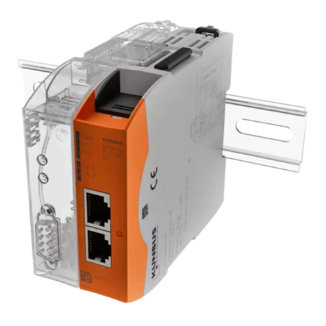
FNL is a gateway between IP-based Ethernet networks
(10/100 Mbit/s) and the field bus PROFIBUS DP.
Overview

FNL 8 / 31
2.2 PROFIBUS DP
FNL supports PROFIBUS DP (RS485 bus) up to 12 Mbit/s The
current configuration is indicated on the side label of the FNL.
1
2
3
4
5
Illustration1: FNL DP
1RS232 service interface [}16]
2Ethernet socket 10/100 RJ45 [}12]
324V supply voltage [}11]
4LEDs [}17]
5PROFIBUS socket RS485 [}13]
Overview

FNL 9 / 31
2.3 PROFIBUS PA
FNL supports PROFIBUS PA (IEC1158-2 bus) with 31.25 Kbit/s. The
current configuration is indicated on the side label of the FNL. FNL is
not intrinsic save. To connect FNL to intrinsic save PROFIBUS PA
networks intrinsic save barriers must be used.
1 2
3
4
5
Illustration2: FNL PROFIBUS-PA/31.25 KBit/s
1Service-Interface RS232 and 24V output for PA power supply [}16]
2PROFIBUS-PA socket [}14]
3Ethernet-socket 10/100 RJ45 [}12]
424V supply voltage [}11]
5LEDs [}17]
Overview

FNL 10 / 31
3 Install
3.1 Assembly
The FNL module is designed for hat rail assembly according to DIN
50022.
◦ Take the device out of the box and hold it upright so that the letters are
legible.
◦ Now, position the recess for the rail right above the hat rail and press
the device downwards until it snaps in.
Install

FNL 11 / 31
3.2 Connect Power Supply
The power supply basis for the FNL module is 24 V DC. The
following options for a correct connection exist:
0 V is to be connected either to clamp 9 or 10 whereas +24 V to
clamp 11 or 12.
The resulting free clamps can be used for distributing the power
supply to other 24 V devices in the cabinet.
The four clamps are to be combined in one plug which is coded for
the sake of an unmistakable assignment. It can be inserted manually
and removed again with a screwdriver.
The power up current impulse of FNL is round about 1.5 A. The used
power supply may not switch off at this charge.
Illustration3: Power supply connection
Clamp Assignment
9 0V
10 0V
11 +24V
12 +24V
Install

FNL 12 / 31
3.3 Connect Ethernet
The Ethernet 10/100 baseTX is to be connected to the front part of
the RJ45 connector. To do so, insert the corresponding plug until it
snaps in. The shield is connected to the hat rail. Please note that the
transmission rate adjusts itself automatically: the slowest rate on the
network determines the speed. For connection to an existing
network, connect the FNL onto the corresponding hub or switch via
patch cable. For direct connection without use of a hub or a switch, a
cross-wired Ethernet cable is required.
Install

FNL 13 / 31
3.4 Connect PROFIBUS DP RS485
NOTICE!The following section is intended for product variant PR
10110801.
The PROFIBUS DP is connected to the front side of the module on
the 9-pin DSUB, as depicted in Figure 3: Connections and Plugs FNL
with PROFIBUS DP/12 Mbit/s. In case the FNL module is the last
unit in the bus chain, a terminator will have to be installed. All
common PROFIBUS plugs already include a terminator, which can
be switched on or off. Please tighten the assembly screws of the
plug. The shield is automatically connected to the hat rail.
Pin-No. Signal Function Direction
1 - shielding
3 R x D / T x D - P data+ input/output
5 0 V (potential free 80 mA) supply terminator output
6 5 V (potential free 80 mA) supply terminator output
8 R x D / T x D - N Data- input/output
Table1: Pin Assignment
NOTICE!For correct operation of the PROFIBUS a terminator has
to be installed on each end of the bus.
Illustration4: PROFIBUS Bus Terminator
Install

FNL 14 / 31
3.5 Connect PROFIBUS PA
NOTICE!The following section is intended for product variant PR
1011085.
The PROFIBUS PA (IEC1158-2) is accessible via clamps 13, 14, 15,
16, which are to be combined in one plug which is coded for the sake
of an unmistakable assignment.
The connector to PROFIBUS PA complies with the specification of
the PNO.
Klemme Funktion
13 is the shield and is connected to the hat rail. It can be
combined with a strain relief which is plugged into the
clamp. This part is included in the package.
14 is the 24 V input of the internal PA power supply.
If internal PA power supply is to be used, this input will
have to be connected to the +24 V output (s. RS232-
Service-Schnittstelle [}16])) via an external wire. If an
external PA power supply is used, this line will remain
open. External power supplies are necessary when
working with a large number of PA subscribers or at
high temperatures. Please, find more details in the part
„Technical Data
15 is the positive signal line to the PA bus (PA+).
16 is the negative signal line to the PA bus (PA-).
The PA bus terminator is installed inside the FNL. The terminator
cannot be switched off. It is important for another terminator to be
installed at the other end of the bus.
Install

FNL 15 / 31
1
2
Illustration5: Connection PROFIBUSS PA
1 Connection to RS232 interface 2 Connection to PROFIBUS PA
(IEC1158-2)
Install

FNL 16 / 31
3.6 Connect Service Interface
RS232 Service Interface
To configure the FNL, terminals can be connected via the terminal
connection (RS232/V24). In general, the terminal consists of a PC
with corresponding terminal emulation. We recommend hyper
terminal under Windows XX. What can be controlled or observed via
the terminal is described in the section „Setting into Operation“.
Clamps 5 … 8 serve as terminal connection and as 24 V output for
the internal PA power supply.
Clamp Voltage Usage
5 24V supplies the 24 V that are needed to activate
the internal PA power supply (only available
with the PA Version of FNL) .
6 0V is the 0 V for the RS232 interface.
7 V24 level is the outgoing data line of the RS232 interface
from viewpoint of the FNL.
8 V24 level is the incoming data line of the RS232 interface
from viewpoint of the FNL.
Pin assignment RS232-
Interface cable
5 6
7
GND GN D
T x D2
Rx D
D S U B 9 f e m a l e
8 Rx D3
T x D
b r
ws
g e
b r
ws
g e
Illustration6: RS232 cable
Install

FNL 17 / 31
4 Signals and fault indication
4.1 LEDs
The LEDs depicted above have the following meaning:
BF* bus failing, red, lighting whenever the PROFIBUS is not yet con-
figured or cannot be operated
Run* bus running, green, lighting while the PROFIBUS is in operation.
Rec receiving, green, lighting while the FNL is receiving data on the Eth-
ernet
TX transmitting, green, lighting while the FNL is sending data on the
Ethernet
LNK link active, yellow, lighting when there is a logical connection
between the FNL and the superior Ethernet partner
100 100 Mbit/s, red, lighting while the Ethernet communication is running
on 100 Mbit/s. At 10 Mbit/s the LED is off. The data rate adjusts
automatically and cannot be manually selected.
* for FNL with PROFIBUS-DP/12 MBit/s
Signals and fault indication

FNL 18 / 31
5 Configure FNL
5.1 Software Installalation
KUNBUS and TMG i-tec offer different software packages for the
FNL:
– KUNBUS Network Configurator Tool
Basic tool for FNL Network configuration
– KUNBUS OPC Server for Windows NT/2000/XP/7
Data Access 2.0 OPC Server incl. configuration tool and OPC test client
– KUNBUS FDT comDTM
FDT 1.2 Communication DTM for FNL to be used with FDT compatible
frame applications like PactWARE or FieldCare.
– KUNBUS TCP/IP socket based programming interface
TCP/IP Socket based programming interface for the integration of FNL
with any operating system platform. To compile the PROFIBUS DP
configuration the configuration tool CONFIGURATOR III is included in
scope of delivery.
– KUNBUS Modbus TCP Interface
Modbus TCP Server V1.1 compatible Ethernet interface for the
connection to any Modbus TCP Client application. To compile the
PROFIBUS DP configuration the configuration tool CONFIGURATOR III
is included in scope of delivery.
The FNL network configuration is performed via Ethernet by the tool
KUNBUS Network Configurator.
The Ethernet based network configuration of FNL is possible from
version 5.02. Older versions of FNL must be configured via the
RS232 service interface.
◦ Start the program KUNBUS Network Configurator from the windows
start menu KUNBUS GmbH/KUNBUS Network Configurator.
◦ Click on to the Search icon
ðKUNBUS Network Configurator scans the network and displays all
found KUNBUS Ethernet devices:
Configure FNL

FNL 19 / 31
5.2 Configure FNL
Configuration of the FNL TCP/IP Address
Double click the appropriate FNL in the displayed list and enter the
TCP/IP Address, Subnet mask und Gateway.
– TCP/IP-Address
– SubNet-Mask
– Gateway
Illustration7: Set TCP/IP-Address
Configure FNL

FNL 20 / 31
Configuration of operation mode (FNL Mode)
FNL supports two operation modes to ensure the downwards
compatibility to previous FNL versions.
Illustration8: Set operation mode
KUNBUS Interface The operation mode KUNBUS interface is to be configured for the
use of FNL in combination with the following applications:
– KUNBUS TCP/IP-Socket-based programming interface
– MODBUS TCP Server Interface
– FNL LabVIEW Driver
For details refer to the related documentation within scope of delivery
of the particular application.
Configure FNL
Other manuals for FNL Series
1
This manual suits for next models
1
Table of contents
Other Kunbus Gateway manuals

Kunbus
Kunbus FNL Series User manual

Kunbus
Kunbus PR100069 User manual

Kunbus
Kunbus PR100066 User manual

Kunbus
Kunbus Sercos Series User manual

Kunbus
Kunbus XPS-E User manual

Kunbus
Kunbus PR100074 User manual

Kunbus
Kunbus PROFINET IRT Slave User manual

Kunbus
Kunbus PR100073 User manual

Kunbus
Kunbus PR100088 User manual
Popular Gateway manuals by other brands

HMS Networks
HMS Networks Anybus Communicator user manual

ZyXEL Communications
ZyXEL Communications LTE5121 quick start guide

Yolink
Yolink YS1603-UC Installation manual & users guide

Sercomm
Sercomm DG4244 Basic user's guide

AudioCodes
AudioCodes Mediapack mp-11x Specifications

WOXTER
WOXTER domotify DO26-002 user manual