Kunz AcrEase H60T User manual

60” FINISH CUT
C60
K
H60T
H60B
OWNER’S MANUAL
For Models: H60T, H60B & C60K
KUNZ ENGINEERING, INC. / PH (815) 539-6954
With Assembly Instructions
MENDOTA, IL 61342 /
1/09

SAFETY INTRODUCTION
Your safety, and the safety of others, is very important. To help you make informed
decisions about safety, we have provided operating procedures and other information on
labels and in this manual. This information alerts you to potential hazards that could hurt
you or others.
You will find important safety information in a variety of forms, including:
Safety Labels – on the mower.
Safety Messages – preceded by a safety alert symbol and one of three signal
words: DANGER, WARNING, or CAUTION.
These signal words mean:
DANGER: Indicates an imminently hazardous situation that, if not avoided, will result in
death or serious injury. This signal word is to be limited to the most extreme situations
typically for machine components which, for functional purposes, cannot be guarded.
WARNING: Indicates a potentially hazardous situation that, if not avoided, could result in
death or serious injury, and includes hazards that are exposed when guards are removed.
It may also be used to alert against unsafe practices.
CAUTION: Indicates a potentially hazardous situation that, if not avoided, may result in
minor or moderate injury. It may also be used to alert against unsafe practices.
This entire manual is filled with important safety information. Please read it
carefully.
1

IMPORTANT SAFETY INFORMATION
WARNING: Do not allow anyone to operate this equipment who has not fully read and
comprehended the safety manual and who has not been properly trained in the safe
operation of the equipment.
WARNING: Operator should be familiar with all functions of the unit.
DANGER: Keep hands, feet, hair and clothing away from moving parts.
WARNING: Remove all objects from the work area that might be picked up and thrown by
the blades.
WARNING: Do not mow when children and others are around.
WARNING: Keep all safety shields and deflectors in place during operation.
WARNING: Shut off the engine and allow the mower blades to come to a complete stop
before making any adjustments to the mower.
WARNING: Shut off engine before disconnecting the wing mower from the tow vehicle or
attempting to move the wing mower by hand.
WARNING: Never carry children or passengers.
WARNING: Do not allow children to operate this machine.
This entire manual is filled with important safety information. Please read it
carefully.
2

SAFETY SIGNS AND LOCATIONS
WARNING: Clean or Replace Any Safety Signs That Are not Readable or Damaged
Replacement decals can be purchased from your local dealer or
275007 –
Warning Decal,
Belt Shield
275003 –
Danger Decal,
Cut Hand & Foot
275002 – Warning Decal,
General
Serial # & Model # Decal
Kunz Engineering Inc.
Mendota, IL 61342
(815) 539-6954
www.kunzeng.com
3

ASSEMBLY INSTRUCTIONS
READ THE COMPLETE ASSEMBLY INSTRUCTIONS BEFORE STARTING THE ASSEMBLY.
You should have:
-one mower deck assembly
-two caster assemblies
-two rear axle assemblies
-one tongue assembly (Lawn & Garden Hitching or ATV Tongue)
-one tow vehicle hitch assembly (only included on Lawn & Garden Hitching)
Optional hitches:
-one tongue extension
-one rear hitch assembly
A. ASSEMBLY OF MOWER WHEELS
1. Set the mower deck assembly on wood blocks so that it is suspended off the ground.
Retainer Bolts
Tongue Pivot Bolt Tongue – Attach to Either
Left or Right Caster Assy.
Left Rear Axle Assy.
.
Left Caster Assy.
Figure 1. Assembly of Wheels, Tongue and Rear Hitch
2. Install the two caster assemblies in the retainers on the front of the mower deck. See figure 1
Before securing the caster supports, determine which side of the mower the tongue will be
placed on and install the caster support stop on the tongue side. See Figure 2. Secure with
3/8” x 2-3/4” hex head bolt, lock washer, and nut provided in the retainer areas.
Note: The operator controls are on the front of the deck and the discharge chute is on the right
side. (Left and right are determined from looking in the direction of travel.)
3. Install the two rear axle assemblies in the retainers on the rear of the mower deck. The tire
should be to the left of the axle support. See figure 1. Secure with 3/8” x 2-1/2” hex head
bolt, lock washer, and nut provided in the retainer areas.
4

Note: Tighten the four wheel assembly pivot bolts so that the wheel assemblies will not flop
down when the deck is raised off the ground.
Caster Support Stop Tongue
Caster Support
Figure 2: Installation of Caster Support Stop
B. INSTALLATION OF LAWN & GARDEN HITCHING (refer to the Operation and Adjustment
Section for recommended hitching)(if the ATV Tongue was purchased refer to section C.
Installation of ATV Tongue)
1. The tongue can be installed either on the left or right caster assembly depending on how the
wing mower will be towed. See figure 1. Tighten the lock nut on the 3/8” x 2-1/2” pivot bolt so
the tongue is free to pivot but does not move sideways.
Note: The tongue can be installed upside down so it will match up with tow vehicles with
higher hitches.
2. The tow vehicle hitch provided is a universal hitch that should fit most tow vehicles. Slight
modifications may be necessary for some tow vehicles.
3. Attach the tow vehicle hitch to the tow vehicle draw bar top or bottom depending on best
support, and secure with the longer 1/2” hex head bolt, flatwasher, nut, and lockwasher
provided. See figure 3.
Note: On some tow vehicles the draw bar will need to be strengthened to support the hitch
assembly securely.
4. Adjust the hitch stop angle with stop bolts as close as possible to the vertical member on the
back of the tow vehicle and adjust stop bolts securely against vertical member to keep hitch
from pivoting from side to side.
Note: The hitch should be positioned on the tow vehicle so the stop bolts have a solid member
to adjust to. On most tow vehicles two bolts can be used to attach the hitch assembly to
the draw bar, eliminating the need for the hitch stop angle.
5

5. The telescoping hitch can either be installed to the left or right and should clear the back of the
tire by about 2”.
6. If one mower is pulled on both the left and right side of the tow vehicle, then one telescoping
hitch can be mounted to the left and one to the right.
Telescoping Hitch - Install to Left
or to Right or in Both Directions
When Pulling Two Wing Mowers. Hitch Stop Angle
Adjust Stop Bolt to
Back of Tow Vehicle
Figure 3: Installation of Tow Vehicle Hitch
Figure 4. Assembly of Hitch Pivot and Tongue
Screw Pin
Shackle Clevis
Hitch Pivot – Attach
to either Left or Right
Caster Assy.
Tongue
Offset Tongue Position Direct Behind Tongue Position
6

C. INSTALLATION OF ATV TONGUE ASSEMBLY (if the lawn and garden hitching was purchased
refer to Section B. Installation of Lawn & Garden Hitching)
1. The tongue can be installed either on the
left or right caster assembly depending on how the
wing mower will be towed. See figure 4. Secure the hitch pivot on the chosen caster
2 the hitch pivot and secure by placing a 5/16” wire lock pin on each side
of the hitch pivot.
D. INSTALLATION OF OPTIONAL HITCHES
1. When a long tong rom the tongue
assembly and atta in between the
Figure 5: Long Tongue Assembly and Rear Hitch Assembly
D ADJUSTMENTS
assembly with the 3/8” x 2-1/2” hex head bolt, lock washer, and nut provided.
. Install the tongue into
ue is needed, remove the tongue pivot angles and spacer f
ch to the tongue extension. See figure 5. Slip the tongue
two flats on the tongue extension and secure with 3/8” x 2-1/2” hex head bolts, lock washers,
and nuts provided.
2. When a second mower is pulled behind the first mower in tandem, then the rear hitch can be
installed on the left rear axle assembly. See figure 5. Secure with 3/8” x 3-1/4” hex head
bolts, lock washers, and nuts provided.
Note: The long tongue extension (Part # 900008) and rear hitch assembly (Part # 900009) must
be ordered separately.
Long Tongue Extension
Spacer
Tongue Pivot Angle Rear Hitch Assembly
Attach to Left Rear Axle
Short Tongue
OPERATIONS AN
This safety alert symbol is used to indicate safety instructions. Follow
these instructions to avoid personal injury and/or property damage. Read
and follow all instructions in this manual and the included engine manual.
WARNING: Do not allow anyone to operate this equipment who has not fully read and
comprehended the safety manual and who has not been properly trained in the safe
operation of the equipment.
WARNING: Operator should be familiar with all functions of the unit.
7

A. HITCH
WARNING: Shut off the engine and allow the mower blades to come to a complete stop
before
CONFIGURATIONS (Refer to Figure 6)
adjusting the spreader hitch on the tow vehicle.
Tow Vehicle without a Mower Deck
Tow Vehicle with a Mower Deck
1 & 2 combined
or 5 1, 2, & 3 combined
or 5 2 & 4
combined
2 & 3
combined
1 & 2 combined
or 5 1, 2, & 3
combined
1 & 2
combined
2 & 4
combined
1, 2, & 3
combined
1 & 2
combined
Listed above are all of the possible configurations of the wing mowers. The
numbers listed below each wing mower correspond to the hitch or combination of
hitches required to complete that possible configuration.
1. Tow Vehicle Hitch (Telescoping Hitch)
2. Short Tongue
3. Long Tongue Extension
4. Rear Hitch Assembly
5. ATV Tongue Assembly
Figure 6: Wing Mower Towing Suggestions and Required Hitches
8

The hitching system is designed so that the wing mower can be pulled directly behind a tow
vehicle without a mower deck or as a left or right wing mower when towed behind a tow vehicle
with or without a mower deck.
If more n
the rig ions until the desired cutting width is obtained.
foot
ould
e open areas, adjust the spreader hitch on the tow vehicle so that the wing
mower tongue center line aligns with the outside cut line on the tow vehicle mower. When
adjust the tow vehicle hitch in to
liminate skips. The spreader hitch can be adjusted in and out to get the desired overlap to fit
your m
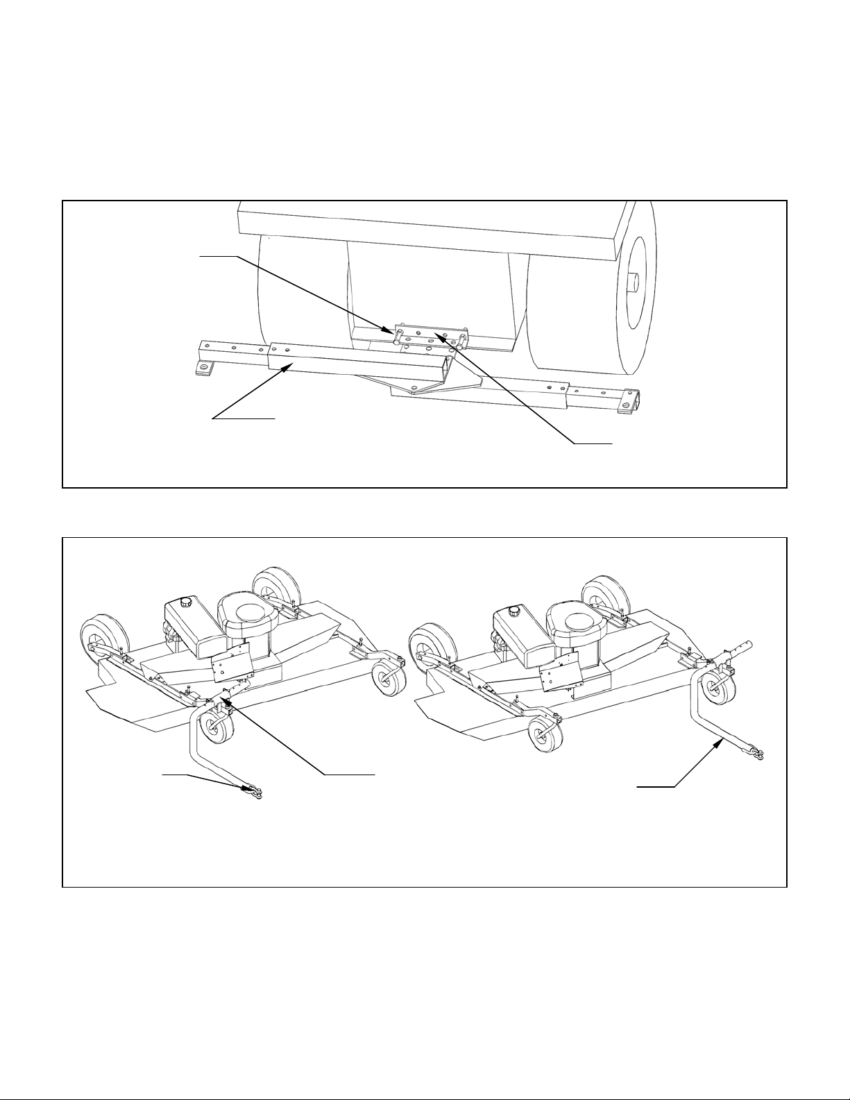
B. ATV TONGUE CONFIGURATIONS (Refer to Figure 6)
op
w
d the wing mower becomes unattached from the tow vehicle.
The
vehicle wit
with or wit
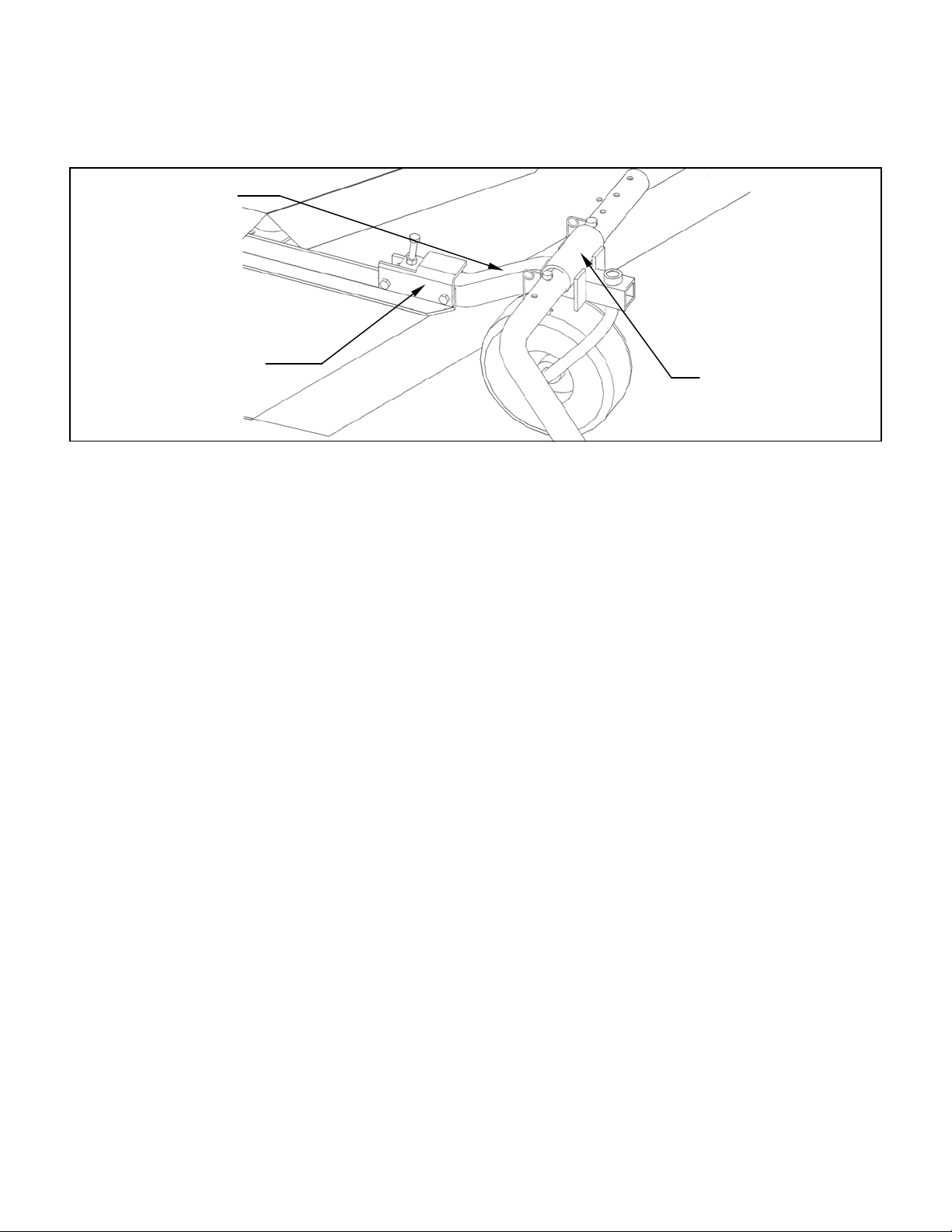
Note: When pulling the wing mower directly behind, it is most maneuverable when the hitch
er in
t
om left to right within the hitch pivot. This allows the wing
mower and tow vehicle, with a mower deck, to have proper overlap. Overlap is more critical in
tight areas where a lot of maneuvering is required. This overlap will eliminate most skips between
the tow vehicle and wing mower. In large open areas the overlap is not as critical and should be
adjusted to the user’s preference.
than one wing mower is towed, they can be pulled in tandem or one on the left and one o
ht or a combination of the above condit
CAUTION: Do not operate two wing mowers in tandem on slopes greater than 25% (1
rise, 4 foot run). This can create an unstable condition where the rear wing mower c
push the front wing mower sideways.
When mowing larg
trimming around objects or mowing contours, it is best to
e
owing job.
WARNING: Shut off the engine and allow the mower blades to come to a complete st
before adjusting the tongue.
WARNING: When attaching the tongue to the back of the tow vehicle, tighten the scre
pin shackle clevis firmly. Property damage or bodily injury may occur if the screw pin
shackle clevis unturns an
hitching system is designed so that the wing mower can be pulled directly behind a tow
hout a mower deck or as a left or right wing mower when towed behind a tow vehicle
hout a mower deck.
pivot is fastened on the left carrier arm. See Figure 4.When pulling the wing mow
the offset position, it is most maneuverable to have the hitch pivot fastened on the righ
carrier arm. See Figure 4.
The tongue is designed to adjust fr
9

C. ADJ
The cutting height can be adjusted in a range from 1.0" to 4.0". This is accomplished by adjusting
mower
cutting height.
important to have all the mowers adjusted
on to a smooth, level surface.
Adjust the tow vehicle mower deck (If applicable) to the desired cutting height and level both
fore
3. Me the mower blade cutting edge on the tow
vehicle.
fore
eight
USTING CUTTING HEIGHT
WARNING: Shut off all engines and allow the mower blades to come to a complete stop
on the wing mowers and on the tow vehicle before adjusting the cutting height.
the height adjusting bolts on each of the four corners of the wing mower. See Figure 7. Turn the
bolts clockwise to raise the mower cutting height and counter-clockwise to lower the
When more than one mower is used at a time, it is very
as close to the same cutting height as possible to obtain a high quality cutting job.
Adjust the mowers as follows:
1. Pull the mowing unit
2.
and aft and side to side.
asure the distance from the level surface to
DANGER: Shut off tow vehicle engine and allow mower blades to stop completely be
attempting to measure the cutting height.
Figure 7: Adjusting Wing Mower Cutting H
Adjust Anti-Scalp Wheels
Under Deck to the Upper or
Lower Cutting Range Height Adjustment Bolts
Snug 4 Bolts to
Eliminate Side
Movement
Cuttin
g
Hei
g
ht
Measure the Distance
and Add 5/16” to get
Cutting height
Mower Blade
Lower Edge
of Deck
Adjust for Upper or
Lower Cutting Range
5/16”
Smooth Surface
10

4. Adjust the cutting height on the wing mower so that it cuts at the same height as the tow
surface r
blade c
ote: To mow in the lower half of the cutting range, set the front caster axles in the bottom
e
Note: After the cutting height has been set, be sure to tighten the pivot bolts securely to
e pivoting of the front casters or rear axles. Snug the four bolts just beyond
the height adjust bolt so the front casters and rear axles can be adjusted up and down
D. S
wer unless it is attached to the tow vehicle.
Set the choke to the desired position.
Set the throttle lever in the start position at about half throttle. The mower blades clutch will
mes up to speed. The mower blades clutch engages at 1850 RPM.
Adju
Adjust engine speed to full throttle to fully engage the mower blades clutch.
CAUTION: Clutch overheating or failure may occur if engine is not run at full speed in
heavy load conditions.
CAUTION: The engine full speed setting with mower blades running is 3350 RPM.
vehicle mower. Adjust each corner of the wing mower so that the distance form the smooth
to the bottom edge of the deck is equal to the cutting height minus 5/16”. The mowe
utting edge is 5/16” above the lower edge of the deck.
N
setting and set the anti-scalp wheels in the top hole. To mow in the upper half of th
cutting range (original factory setting), set the front caster axles in the top setting and
set the anti-scalp wheels in the bottom hole.
eliminate fre
but cannot move from side to side.
TARTING ENGINE
WARNING: Set parking brake on tow vehicle.
Attach wing mower tongue to tow vehicle.
WARNING: Do not start wing mo
Turn on fuel shut off valve which is located on the underside of the gas tank.
engage as the engine co
Start engine and allow engine to warm up.
st the choke to off.
11

E. SHUTTING OFF WING MOWER
WARNING: Shift to neutral, disengage power to the mower deck, and set the parking
wn for a short time before turning the engine off.
Turn
F. MOWE
CAUTION: Clean or replace any safety signs that are not readable or damaged.
WARNING: Remove all objects from the work area that might be picked up and thrown by
ty shields and deflectors in place during operation.
Dry grass build up around belts and
sheaves can cause fires.
WARNING: Shut off engine before disconnecting the wing mower from the tow vehicle or
WARNING: Do not allow children to operate this machine.
over.
drop
Back er challenge as additional
wing mowers are towed. Avoid backing up by planning ahead. Make loops instead of backing.
brake before dismounting the tow vehicle.
Set the throttle to slow so the mower blades clutch will disengage.
Allow engine to cool do
off fuel shut off valve which is located on the underside of the gas tank.
R OPERATION
DANGER: Keep hands, feet, hair and clothing away from moving parts.
the blades.
WARNING: Do not mow when children and others are around.
WARNING: Do not fill fuel tank while engine is running or hot.
WARNING: Keep all safe
CAUTION: Remove grass build up from under safety shields before each use. Do not
remove safety shields while engine is running.
attempting to move the wing mower by hand.
WARNING: Never carry children or passengers.
CAUTION: Slow down and watch the ends of the wing mowers when making turns so
objects are not struck and/or run
Depending on the number of wing mowers being towed, it is usually more efficient to mow the
large areas first with the full system. Once the large areas are completed, mowers can be
ped off to mow narrower areas.
ing up with one wing mower is easy. Backing becomes a great
12

WARNING: Look down, to the sides, and behind before and while backing to avoid
backing over something or someone. Care should also be taken while backing so that t
wing mower or mowers do not jackknife and damage hitches.
he
wers before attempting to push or pull the tow vehicle.
causing
damage to the hitches.
o
wing
mowers are towed with one on the left and one on the right side, there will be a lot of material
tch slippage for a few seconds will not cause damage. If the clutch
is allowed to slip for longer periods, it will overheat and could be damaged. Watch the discharge
chute tch
slipp lutch
sprin
CAUTION: If the mower blades are allowed to stall out (stop turning) at engine speeds
, this will cause the clutch to slip. If the clutch is
allowed to slip for more than five minutes, the clutch will get red hot and could cause the
G. DRIVE BELT REMOVAL AND TENSION
WARNING: Shut off engine and allow mower blades to stop turning before making any
nut until the belt can be slipped off the
Slip the belt down under the drive sheave and off the blade spindle sheaves.
WARNING: Stop the mower blades on both the tow vehicle and all wing mowers if the tow
vehicle becomes stuck or stops going forward because of loss of traction. Shut off the
engines on the wing mo
CAUTION: Do not turn too sharply when the wing mowers are pulled in tandem or pulled
behind a zero turn mower. Sharp turns can force the mowers into each other
Listen to the wing mower engines while mowing. The engines should run free and not work to
hard. Working the engine too hard will cause overheating and premature failure.
Do not allow material to build up on the air inlet to the engine cooling system. If the
blowing around the right wing mower engine. Special care should be taken to make sure the
engine is getting enough inlet air. Do not allow the engine cooling fins under the shroud to be
blocked. Air flow over the engine will be restricted causing the engine to overheat.
Mowing to fast in very heavy, long grass can cause the wing mower engine to pull down and
disengage the blade clutch. The engine can then start to accelerate again while slipping the
clutch. Small amounts of clu
; if material is not being discharged, then the clutch is slipping. In normal conditions, clu
age will not be a problem. In most cases the clutch can be repaired by replacing the c
gs and clutch bearing.
above the clutch engagement speed
drive belt to start burning.
adjustments or repairs.
Remove the safety shields.
Loosen the nuts on the spring-loaded idler; adjust the
idler and drive sheaves.
Install the new belt and adjust the tension as follows:
13

Models H60T & H60B: – See Figure 8.
Adjust the spring-loaded idler springs to a compressed length of 15/16” initially for a few hours
st the spring to 1-1/8” to 1-1/4” compressed length.
Model C60K:
until the belts run in; then adju
Fron
t
Engine
Initial Spring Length 15/16”
Running Spring Length 1-1/8” to 1-1/4”
Figure 8: Belt Pattern and Spring Adjustment (Model H60T & H60B)
– See Figure 9.
f 15/16” initially for a few hours
ntil the belts run in; then adjust the spring to 1-1/8” to 1-1/4” compressed length.
Figure 9: Belt Pattern and Spring Adjustment (Model C60K)
Adjust the spring-loaded idler springs to a compressed length o
u
Front
Engine
Initial Spring Length 15/16”
Running Spring Length 1-1/8” to 1-1/4”
14

H.
blades can cause bodily injury if not handled properly.
When the blade
nd the underside of the mower deck. This will allow the removal of the blade without the need to
CAUTION: Always balance the mower blades each time they are sharpened.
Out of s,
bolts coming loose, and overall deterioration of the wing mowers.
o
he Models H60T and H60B use the Kunz Engineering Part # (202134) blade bolt. This particular
eering Part # (202136) blade bolt. This particular hex head bolt is a
/2” – 20NF x 1.00” long, grade 5 and it’s proper torque is 85 ft-lbs.
I.
caster wheel pivots, four wheels (on models that apply), and three blade spindles (on models that
app
Lubricate
hold the s ing lubrication.) Lubricate with a high grade of pressure gun grease.
er grease blade spindles. Blade spindles are initially greased at the factory.
eel
en they are stepped on.
K. RANSPORTATION OF MOWER
hen transporting the mowers between jobs turn off the fuel shut-off valve. The fuel shut-off
valve is located below the fuel tank.
MOWER BLADE REMOVAL, BALANCING & INSTALLATION
CAUTION: Sharp
removing the blade, it is recommended that a block of wood be placed between
a
hold the blade by hand.
balance mower blades cause excess vibrations which lead to premature bearing failure
CAUTION: Always properly tighten the blade bolts to the specified torque. Failure to do s
can lead to unwanted loosening of the blade and damage to the blade holding saddle.
T
hex head bolt is a 3/8” – 24NF x 7/8” long, grade 5 and it’s proper torque is 35 ft-lbs. The Model
C60K uses the Kunz Engin
1
To ease in the blade installation process, use the same block of wood and method used during
the removal of the blades.
LUBRICATION
There are up to ten lubrication points on the wing mower -- one spring-loaded idler pivot, two
ly). Lubricate at approximately 10 hr. intervals or more often as required in dusty conditions.
the blade spindles 2-5 pumps every 50 hours. (The bearings have trash guard seals to
eals in place dur
Note: Do not ov
Greasing before 50 hrs. may cause bearing seal damage which will result in premature
bearing failure.
J. TIRE PRESSURE
To reduce wing mower bounce on rough yards, the rear tire pressure can be reduced so they f
slightly soft (approximately 15 PSI) wh
T
W
15

L. TORAGE
urn off fuel shut off valve which is located on the underside of the gas tank. If the mower is
stored outside, the engine should be covered to prevent water from getting inside the engine
during heavy rainstorms. See the Engine Manual for additional information.
S
T
16

WING MOWER SPECIFICATIONS
Model Model Model
H60T C60K H60B
ENGINE:
Engine Make Tecumseh Enduro Kohler Command Pro Bri
gg
s & Stratton
Engine Model OHV130-EXE CV 493 Intek
Cylinders 1 1 1
Cycles 4 4 4
Crankshaft Vertical Vertical Vertical
Engine HP 13 18 17.5
Bore 3.31" 3.54" 3.57"
Stroke 2.53" 3.03" 3.06"
Displacement 21.82 cu.in. 29.9 cu.in. 30.6 cu.in.
Oil Capacity 1 U.S. qts. 2 U.S. qts. 1.5 U.S.
q
ts
Crankshaft Dia. 1" 1" 1.0"
Key Slot 1/4" 1/4" 1/4"
Crankshaft Length 3.15" 3.15" 3.15"
Threaded Hole in End of Crankshaft 7/16-20 7/16-20 7/16 - 20
Engine Mounting Bolts 5/16-18 x 1-1/2 M8 x 1.25 - 25 5/16-18 x 1-1/2
Starter Electric Electric Electric
Choke Manual Manual Manual
MOWER:
Fuel Tank 3-3/4 Gal. 3-3/4 Gal. 3-3/4 Gal.
Effective Cutting Width 58" 58" 58"
Deck Construction 11 ga. Welded steel 10 ga. Welded steel 11
g
a. Welded steel
Cutting Height 1" to 4" 1" to 4" 1" to 4"
Height Adjustment 4 screws 4 screws 4 screws
Anti-Scal p Wheels 4 in front, 2 in rear 4 in front, 2 in rear 4 in front, 2 in rear
(3" O.D. x 1-1/4" wide)
Rear Wheels (Fixed) 2 13/500 x 6 2 13/500 x 6 2 13/500 x 6
(2 ply Turf Pnuematic)
Front Wheels (Caster) 2 9/350 x 4 2 9/350 x 4 2 9/350 x 4
(Semi Pnuematic)
Blade Dia. 3-20" 3-20" 3-20"
Engine Speed, Blades Running 3350 RPM 3350 RPM 3350 RPM
CLUTCH TYPE Centrifugal Centrifugal
Engagement Speed 1850 RPM 1850 RPM 1850 RPM
DIMENSIONS
Length 52" 52" 52"
Width 72-1/4" 72-1/4" 72-1/4"
Height 24-1/2" 25" 24-1/2"
Weight 325# 380# 325 lb
s
TOUCH-UP PAINT COLOR
Pewter Gray, Krylon #1606 Pewter Gray, Krylon #1606 Pewter Gray, Krylon #1606
17

ACREASE WING MOWER PARTS MODEL C60K
18
Item Part # Description C60K
1 202135 Hex Head Bolt, 3/8" x 3" Fully Threaded 4
2 204000 Shoulder Bolt, 1/2" x 1-5/ 8" Shoulder Length 6
3 222005 Worm Drive Hose Clamp (7-7/ 8" to 9-1/ 8" Clamping Dia. 2
4 225000 Compression Spring, 1-1/2"L x 1-3/32" O. D. x .135" Wire dia. 1
5 226000 Plastic Wheel, 3" O.D. x 1/2" I.D. x 1-1/4" Wide 6
6 226001 Offset Wheel Assy., 13/500 x 6, 2 Ply Turf 2
7 226002 Centered Wheel Assy., 9/350 x 4, Semi Pneumatic 2
8 238002 "V" Belt, B Section, 127" O.C. Dayco B124 Super I I 1
9 241001 Flat Idler, 4" O.D. x 3/8" Hole 2
10 258016 Centrifugal Clutch 1
258017 Clutch Shoe (3) ~
225004 Spring, 1850 RPM Engagement (3) (Blue) ~
243004 Bearing (1) ~
11 258020 Spindle Assy. 3
900046 Spindle Shaft (1) ~
900139 Housing Assy. (With Two Bearings) (1) ~
243003 Bearing (2) ~
600204 Bearing Spacer (3-5/ 8" Long) (1) ~
241007 Sheave, 5-1/4" (1) ~
12 259001 Offset Mower Blade, 2" Wide, 20" Long, 1/2" Hole 3
13 264000 Solenoid 1
14 264001 Ignition Switch 1
15 264003 Hour/Tack Meter 1
16 269001 Thrott le Control, 15" 1
17 269004 Choke Control, 14" 1
18 275001 Control Panel Decal, Starting Instructions 1
18 275002 Warning Decal General 1
18 275003 Danger Decal, Cut Finger 2
18 275007 Warning Decal, Belt Sheild 2
18 275019 Name Decal, Kunz 1
18 275021 Name Decal, AcrEase 2
18 275023 Name Decal, 60" Finish Cut 2
19 277002 Rubber Grommet 7
20 277010 Fuel Tank, 3.75 Gal. (Plastic) (Use Gas Cap 277013) 1
21 277013 Gas Cap (For Fuel Tank 277010) 1
22 600048 Solenoid Support 1
23 600059 Caster Axle 2
24 600062 Belt Sheild L.H. 1
24 600063 Belt Sheild R.H. (Discharge Side) 1
25 600065 Engine Support Bracket 1
26 600188 Caster Support Stop 1
27 900005 Rear Axle 2
28 900021 Caster Support 2
29 900023 Control Panel 1
30 900025 Idler Arm Assy. 1
243000 Bronze Bearing, 1/2"I.D. x 3/4" O.D. x 1-1/2" Long ~
31 900029 Mower Deck 1
32 900049 Battery Box Assy. 1
33 900051 Depth Gage 1
34 900052 Tank Support 1

MODEL C60K
21
1
2
3
4
5
6
7
8
10
11
12
14
13
15
16
17
18
19
20
1
22
23
24
25
26
27
28
29
30
31
34
33
32
9
19
This manual suits for next models
2
Table of contents
Other Kunz Farm Equipment manuals

Kunz
Kunz AcrEase MR55B-19HP User manual

Kunz
Kunz AcrEase MR55H User manual

Kunz
Kunz AcrEase MR55KE-ECO User manual

Kunz
Kunz AcrEase Pro60K User manual

Kunz
Kunz Till-Ease User manual

Kunz
Kunz AcrEase H60B User manual

Kunz
Kunz AcrEase H40B User manual

Kunz
Kunz AcrEase MR55KE-25HP User manual

Kunz
Kunz AcrEase MR55VE User manual
Popular Farm Equipment manuals by other brands

Brillion
Brillion HFC Field Commander Series Operator's Manual, Assembly Instructions

Omlet
Omlet Eglu Cube instructions

Spearhead
Spearhead Starcut 300 Handbook

Nogueira
Nogueira NEW PECUS Duo G2 instruction manual

Degelman
Degelman rock rake RR1500 Operator's & parts manual

MacDon
MacDon M2170 Operator's manual