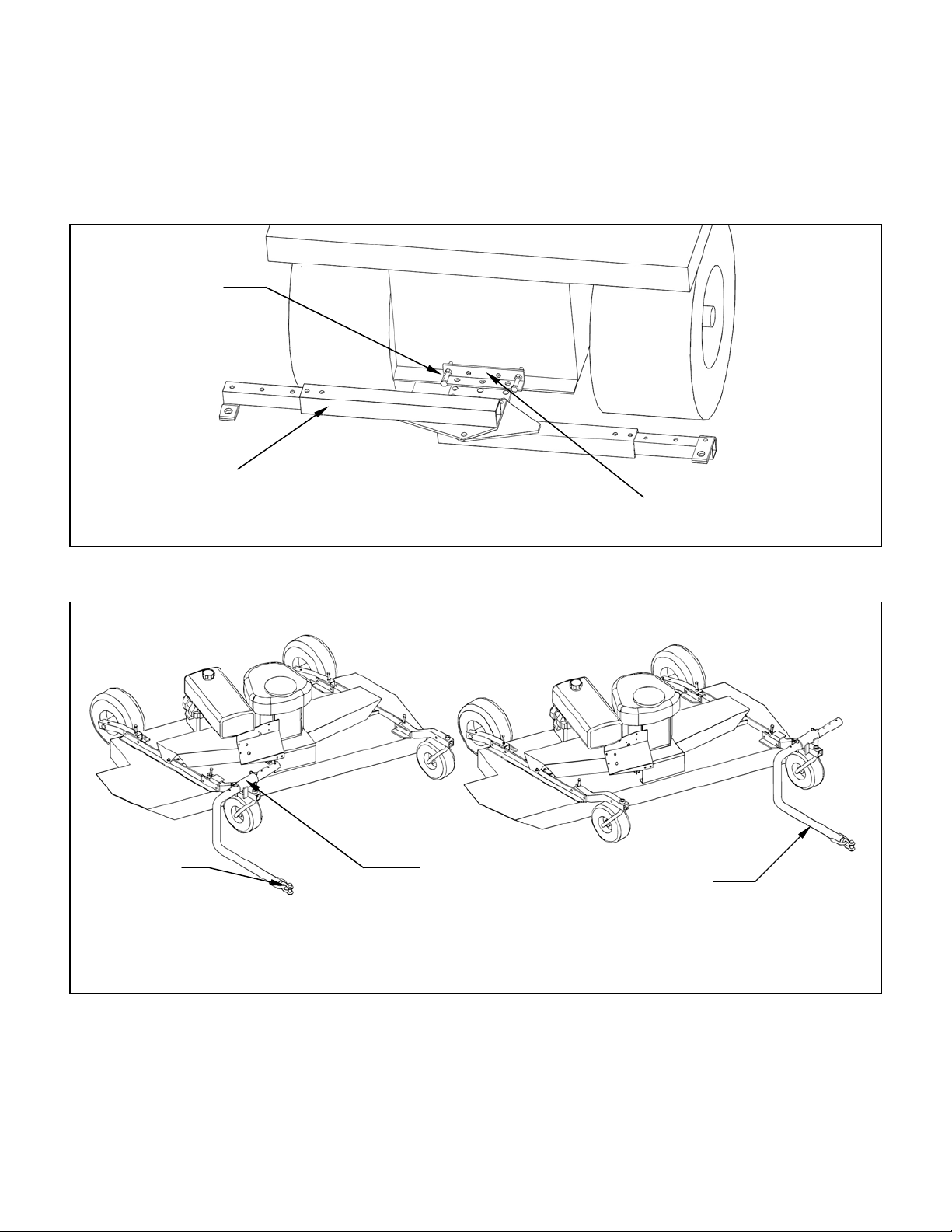
C. INSTALLATION OF ATV TONGUE ASSEMBLY (if the lawn and garden hitching was purchased
refer to Section B. Installation of Lawn & Garden Hitching)
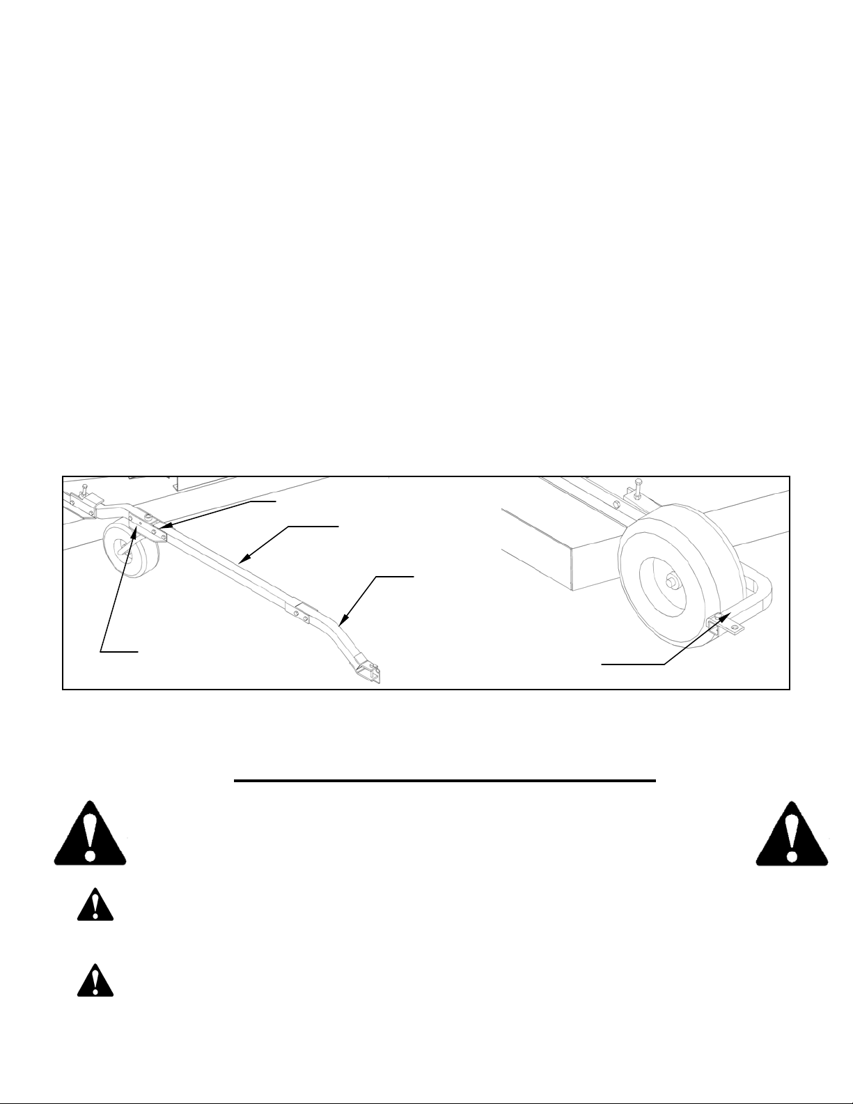
1. The tongue can be installed either on the left or right caster assembly depending on how the
wing mower will be towed. See figure 4. Secure the hitch pivot on the chosen caster
assembly with the 3/8” x 2-1/2” hex head bolt, lock washer, and nut provided.
2. Install the tongue into the hitch pivot and secure by placing a 5/16” wire lock pin on each side
of the hitch pivot.
D. INSTALLATION OF OPTIONAL HITCHES
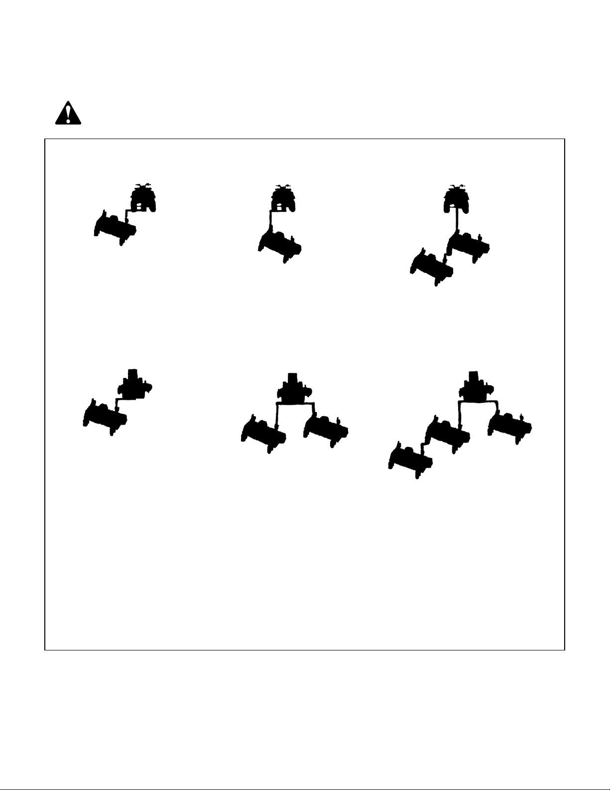
1. When a long tongue is needed, remove the tongue pivot angles and spacer from the tongue
assembly and attach to the tongue extension. See figure 5. Slip the tongue in between the
two flats on the tongue extension and secure with 3/8” x 2-1/2” hex head bolts, lock washers,
and nuts provided.
2. When a second mower is pulled behind the first mower in tandem, then the rear hitch can be
installed on the left rear axle assembly. See figure 5. Secure with 3/8” x 3-1/4” hex head
bolts, lock washers, and nuts provided.
Note: The long tongue extension (Part # 900008) and rear hitch assembly (Part # 900009) must
be ordered separately.
Long Tongue Extension
Tongue Pivot Angle
Spacer
Short Tongue
Rear Hitch Assembly
Attach to Left Rear Axle
Figure 5: Long Tongue Assembly and Rear Hitch Assembly
OPERATIONS AND ADJUSTMENTS
This safety alert symbol is used to indicate safety instructions. Follow
these instructions to avoid personal injury and/or property damage. Read
and follow all instructions in this manual and the included engine manual.
WARNING: Do not allow anyone to operate this equipment who has not fully read and
comprehended the safety manual and who has not been properly trained in the safe
operation of the equipment.
WARNING: Operator should be familiar with all functions of the unit.
8