manuals.online logo
Brands
  1. Home
  2. •
  3. Brands
  4. •
  5. Kuppersbusch
  6. •
  7. Ventilation Hood
  8. •
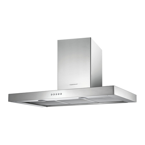
  9. Kuppersbusch LB 635.1 Quick setup guide

Kuppersbusch LB 635.1 Quick setup guide

LB 635.1 - LB 835.1
LBEM 635.1 - LBEM 835.1

Küppersbusch Hausgeräte AG
Postfach 10 01 32, D-45801 Gelsenkirchen, Küppersbuschstr. 16, D-45883 Gelsenkirchen
Telefon: (02 09) 4 01-0, Telefax: (02 09) 4 01-3 03
www.kueppersbusch.de
Küppersbusch Ges.m.b.H.
Eitnergasse 13, 1231 Wien, Telefon: 01 / 8 66 80-0, Telefax: 01 / 8 66 80 72
BEDIENUNGSANWEISUNG
mit Montageanweisungen
GB
Instructions for use and installation instructions
Instructions d'utilisation et avis de montage
Gebruiksaanwijzing en montagehandleiding
Istruzioni di uso e di montaggio
Instrucciones de uso y de montaje
Instruções de uso e de montagem
F
NL
I
E
P
zeigen an, dass die Fettfilter gereinigt werden
nüssen. Sind einmal die gereinigten Filter
wieder eingefügt, so drückt man auf irgend eine
der drei Betriebstasten, um den Timer wieder
einzusetzen.
Wechsel der Kohlefilter (bei Umluftgeräten):
Soweit das Gerät im Umluftbetrieb eingesetzt
wird, sind die Kohlefilter regelmäßig auszu-
tauschen und durch neue zu ersetzen. Die
Austauschhäufigkeit hängt auch hier ab von
der Benutzungsdauer und der Art der abzusau-
genden Wrasen. Mindestens sind die Kohlefilter
alle sechs Monate zu wechseln. Die Kohlefilter
sind am Motorgehäuse befestigt und können
durch Drehung gelöst und in umgekehrter
Drehrichtung befestigt werden (Abb. 13).
Um den/die Fettfilter abnehmen zu können,
muß zunächst das Filtergitter geöffnet werden.
Dies geschieht durch Drehung der beiden
Halterungen nach außen (Abb. 14). Dann ist
die Entfernung der Filter durch seitliches
Herausziehen nach rechts möglich (Abb. 15).
Wechsel der Halogenlampen
Beim Lampenwechsel ist zu beachten daß nach
längerem Betrieb des Gerätes die Lampen sehr
heiß werden. Es empfiehlt sich daher die Lam-
pen in abgekühltem Zustand zu wechseln. Die
Halogenlampen nie mit bloßen Fingern anfas-
sen! Zunächst ist die Lichtabdeckung zu öffnen
(Abb. 16). Nun kann die Halogenlampe gewe-
chselt werden. Im Austauschfall sind unbedingt
Halogenlampen des selben Typs zu
verwenden.
WARNING
--------------------------------------------------
The distance between the supporting
surface for the cooking vessels on the hob
and the lower part of the hood must be at
least 65 cm. If the instructions for installation
for the hob specify a greater distance, this
has to be taken into account.
The air collected must not be conveyed
into a duct used to blow off smokes from
appliances fed with an energy other than
electricity (central heating systems, ther-
mosiphons, water-heaters, etc.).
Comply with the official instructions provided
by the competent authorities in merit when
installing the disposal duct. In addition,
exhaust air should not be discharged into
a wall cavity, unless the cavity is designed
for that purpose.
The room must be well aerated in case a
hood and some other heat equipment fed
with an energy other than electricity (gas,
oil, coal heaters, etc) operate at the same
time. In fact the intake hood, disposing of
air, could create a vacuum in the room.
The vacuum should not exceed 0,04mbar.
This prevents the gas exhausted by the
heat source from being intaken again. It is
therefore advisable to ensure the room
contains air taps able to ensure a steady
flow of fresh air.
ATTENTION: This appliance must be
grounded.
The following warning is valid in the United
Kingdom only: in case your cable is not
furnished with a plug, read the following
instructions; as the colours of the wires in
the mains lead of this appliance may not
correspond with the coloured markings
identifying the terminals in your plug,
proceed as follows:
– the wire which is coloured green and
yellow must be connected to the terminal
in the plug which is marked with the letter
E or by the earth symbol [ ], or coloured
green or green and yellow;
– the wire which is coloured blue must be
connected to the terminal which is marked
with the letter N or coloured black;
English
– the wire which is coloured brown must
be connected to the terminal which is
marked with the letter L or coloured red.
When making the electrical connections,
check that the current socket has a ground
connection and that the voltage values
correspond to those indicated on the data
plate inside the appliance itself.
In case your appliance is not furnished with
a non separating flexible cable and has no
plug, or has not got any other device ensu-
ring omnipolar disconnection from the elec-
tricity main, with a contact opening distance
of at least 3 mm, such separating device
ensuring disconnection from the main must
be included in the fixed installation. If your
unit features a power lead and plug, position
this so the plug is accessible.
Always switch off the electricity supply be-
fore carrying out any cleaning or servicing
operations on the appliance.
USE
--------------------------------------------------
Avoid using materials which could cause
spurts of flame (flambées) near the ap-
pliance.
When frying, take particular care to prevent
oil and grease from catching fire. Already
used oil is especially dangerous in this re-
spect. Do not use uncovered electric grates.
To avoid possible risks of fire always
comply with the indicated instructions when
cleaning grease filters and when removing
grease deposits from the appliance.
MAINTENANCE
--------------------------------------------------
Thorough servicing guarantees correct and
long-lasting operation.
Particular care must be paid to the anti-
grease filters which must be periodically
cleaned in relation to use (at least once
every two months). Remove the grease
filters and wash them either using neutral
detergent.
Any fat deposits should be removed from
the appliance periodically depending on
amount of use (at least every 2 months).
Avoid using abrasive or corrosive products.
To clean painted appliances on the outside,
use a cloth dipped in lukewarm water and
neutral detergent. To clean steel, copper
or brass appliances on the outside, it is
always best to use specific products,
following the instructions on the products
themselves. To clean the inside of the
appliance, use a cloth (or brush) dipped in
denatured ethyl alcohol.
DESCRIPTION
--------------------------------------------------
The appliance can be a filtering version one, a
ducting version one or with an external motor.
In the Filtering version (Fig. 1), the air and
vapours conveyed by the appliance are depu-
rated by charcoal filters and recirculated around
the room.
ATTENTION: When using the filtering version,
two charcoal filters must be installed.
In the Ducting version (Fig. 2), cooking va-
pours and odours are conveyed straight out-
side by a disposal duct which passes through
the wall/ceiling. Use of charcoal filters is there-
fore unnecessary.
In the version with an External motor (Fig. 3),
the appliance must be connected to an ducting
apparatus/motor which works on its own using
the appliance as a union for the air to be scav-
enged. Use only motors "Küppersbusch".
INSTALLATION
--------------------------------------------------
The following operations are essential for as-
sembly:
– Cut a hole in the bottom of the pensile
cupboard in order to settle the appliance
(Fig. 4).
– Install the wiring system.
– Prepare the air venting hole if your appli-
ance is to be installed in the ducting ver-
sion or in the version with an external motor.
Fix the air venting flange onto the apparatus;
according to the version you bought, it must
be fixed either by means of screws (as in Fig.
5 and 6) o pressing slightly (see Fig. 7).
To install the appliance, adjust the position of
the clasping side spring by means of the proper
screws (Fig. 8), according to the thickness of
the bored panel to which it is going to be an-
chored. Insert the appliance in the pensile cup-
board and lock it by means of the side spring.
Use the holes which have already been made
in the casing of the appliance to definitively fix
it by means of additional screws (Fig. 9).
Ducting version
Using a proper pipe, connect the air venting
flange of the apparatus to the air venting hole
you made beforehand.
Make the electrical connection of the hood by
means of the power supply cable.
Filtering version
To the air venting flange of the apparatus con-
nect a proper pipe that can convey the air to
the upper part of the pensile cupboard.
Make the electrical connection of the hood by
means of the power supply cable.
Version with an external motor
Using a proper pipe, connect the air venting
flange of the apparatus to the air venting hole
you made beforehand.
Make the electrical connection between the
hood and the external motor by means of the
proper terminal board (Fig. 10): take off the
cable clamp A and the cover B of the wiring
junction box.
Fix the connection cable of the motor onto the
terminal board C. Reassemble the cable clamp
A and the cover B of the junction box. The
other end of the cable must be fixed onto the
terminal board of the external motor.
Make the electrical connection of the hood by
means of the power supply cable.
OPERATION
--------------------------------------------------
Depending on the model, the unit is equipped
with the following commands:
Commands shown in Fig. 11:
A : light ON/OFF switch.
B : motor ON/OFF - I speed switch.
C : II speed switch.
D : III speed switch.
E : Operating motor warning light.
Commands shown in Fig. 12:
A : light ON/OFF switch.
B : motor ON/OFF - I speed switch.
C : II speed switch - Pressing once more the
timer starts working : it will turn the motor
OFF after a 10’ working time: the led blinks
for all this time.
D : III speed switch - The timer works as for
switch C.
E : IV speed switch - The timer works as for
switch C.
At the end of a working time of about 30 hours,
all the leds blink all together to tell that the
grease filters must be cleaned. After the
cleaned filters are on again, press one of the
three speed switches to allow the counting to
start again.
When using the filtering version of the appli-
ance, the charcoal filters must be changed
according to use (Fig. 13), usually every six
months. Remove the filters rotating them and
replace them rotating into the opposite direc-
tion.
To take off the grease filter/s first open the
grille making the two knobs rotate towards out-
side (Fig. 14); then make the filter/s run to the
right until they get out of the guides (Fig. 15).
To change the rectangular halogen bulbs
open the cover and remove the bulb without
touching it with bare hands (Fig. 16). Replace
with a bulb of the same type.
ATTENTION
---------------------------------------------------
La distance minimum entre la surface de
support des casseroles sur le plan de
cuisson et la partie inférieure de la hotte
doit être de 65 cm. Si les consignes, pour
l’installation du plan de cuisson, indiquent
une plus grande distance, il faut en tenir
compte.
L'air aspiré ne doit pas être canalisé dans
un conduit qui est utilisé pour évacuer les
fumées produites par des appareils alimen-
tés par des sources d'énergies autres que
l'énergie électrique (installations de chauf-
fage central, radiateurs, chauffe-eau, etc.).
Pour évacuer l'air qui doit être éliminé
respectez les prescriptions des autorités
compétentes. De plus l'air qui doit être
évacué ne doit pas être déchargé dans une
cavité du mur, à moins que cette cavité
soit prévue pour ce but.
Prévoyez une aération de la pièce
adéquate quand une hotte et des appareils
alimentés par une énergie autre que
l'énergie électrique (poêle à gaz, à huile, à
charbon etc.) sont utilisés en même temps.
En effet, en évacuant l'air, la hotte pourrait
créer une dépression dans la pièce. La
pression négative de la pièce ne doit pas
dépasser 0,04mbar, évitant ainsi que la
source de chaleur provoque un appel des
gaz qui doivent être évacués. Il est donc
nécessaire d'équiper la pièce de prises d'air
alimentant un flux d'air frais constant.
ATTENTION: cet appareil doit être relié à
la terre.
Lors du raccordement électrique assurez-
vous que la prise de courant est munie de
connexion de mise à terre; vérifiez aussi
que les valeurs de tension correspondent
à celles qui sont indiquées sur la plaque
des caractéristiques de l’appareil, qui se
trouve à l'intérieur de celui-ci. Si votre
appareil, n'a pas de câble flexible qui ne
peut pas être séparé ni de prise, ou bien
d'autre dispositif qui garantisse le dé-
branchement de tous les pôles du réseau,
avec une distance d'ouverture entre les
contacts d'au moins 3 mm, ces dispositifs
Français
de séparation du réseau doivent alors être
prévus dans l'installation fixe. Si votre
appareil est muni d’un câble d’alimentation,
positionner l’appareil de manière à ce que
la fiche soit accessible.
Avant de procéder à une opération
d’entretien ou de nettoyage quelconque,
débranchez l’appareil.
UTILISATION
--------------------------------------------------
Evitez d'utiliser des matériaux qui causent
des flammes à proximité de l'appareil.
Dans le cas de fritures, faites tout particu-
lièrement attention au danger d’incendie
que représentent les huiles et les corps
gras. A cause de son inflammabilité l’huile
usagée est particulièrement dangereuse.
N'utilisez pas de grils électriques
découverts.
Pour éviter des risques d'incendie possibles
suivez les instructions données concernant
le nettoyage des filtres à graisse et sur la
façon d'enlever des dépôts éventuels de
graisse sur l'appareil.
ENTRETIEN
--------------------------------------------------
Un entretien soigné est une garantie de
bon fonctionnement et de bon rendement
de votre appareil dans le temps.
Faites très attention surtout aux filtres à
graisse et nettoyez-les périodiquement (au
moins tous les deux mois). Retirez les filtres
à graisse et lavez-les avec un détersif
neutre.
L’élimination, d’éventuels dépôts de graisse
sur l’appareil, doit être effectuée en fonction
de l’utilisation de ce dernier (au moins tous
les 2 mois). Il faut éviter d’utiliser des
produits contenant des abrasifs ou des
corrosifs. Pour le nettoyage extérieur des
appareils peints, utiliser un chiffon mouillé
avec de l’eau tiède et un détersif neutre.
Pour le nettoyage extérieur des appareils
en acier, en cuivre et en laiton il est
conseillé d’utiliser des produits spécifiques
et de suivre les instructions fournies sur le
produit. Pour le nettoyage de l’intérieur de
l’appareil, utiliser un chiffon (ou un pinceau)
imbibé d’alcool dénaturé.
C
B
A
E
A
B
C
D
min 11
max 21
496-676
261
M
123
45
76
89
10 11
13 14
15 16
12 E
A
B
C
D

This manual suits for next models

3

Other Kuppersbusch Ventilation Hood manuals

Kuppersbusch KD6590.0GE User manual

Kuppersbusch

Kuppersbusch KD6590.0GE User manual

Kuppersbusch DW9350.0 User manual

Kuppersbusch

Kuppersbusch DW9350.0 User manual

Kuppersbusch KD 6210.1 GE-04 Operation manual

Kuppersbusch

Kuppersbusch KD 6210.1 GE-04 Operation manual

Kuppersbusch KD 957.1 GE User manual

Kuppersbusch

Kuppersbusch KD 957.1 GE User manual

Kuppersbusch KD 9760.0 GE User manual

Kuppersbusch

Kuppersbusch KD 9760.0 GE User manual

Kuppersbusch KD 9700.0 User manual

Kuppersbusch

Kuppersbusch KD 9700.0 User manual

Kuppersbusch DI 3800.0 S Operation manual

Kuppersbusch

Kuppersbusch DI 3800.0 S Operation manual

Kuppersbusch DW 3800.0 S Operation manual

Kuppersbusch

Kuppersbusch DW 3800.0 S Operation manual

Kuppersbusch IKD9780.0E Operation manual

Kuppersbusch

Kuppersbusch IKD9780.0E Operation manual

Kuppersbusch EDIP6400.2 Operation manual

Kuppersbusch

Kuppersbusch EDIP6400.2 Operation manual

Kuppersbusch KD 906.3 User manual

Kuppersbusch

Kuppersbusch KD 906.3 User manual

Kuppersbusch IKD 1157.1 User manual

Kuppersbusch

Kuppersbusch IKD 1157.1 User manual

Kuppersbusch KD 9660.0GE Quick setup guide

Kuppersbusch

Kuppersbusch KD 9660.0GE Quick setup guide

Kuppersbusch KD 12450.0 User manual

Kuppersbusch

Kuppersbusch KD 12450.0 User manual

Kuppersbusch DD9800.0S Operation manual

Kuppersbusch

Kuppersbusch DD9800.0S Operation manual

Kuppersbusch 503187 Manual

Kuppersbusch

Kuppersbusch 503187 Manual

Kuppersbusch KD 3700.0 User manual

Kuppersbusch

Kuppersbusch KD 3700.0 User manual

Kuppersbusch DEF6800.0 User manual

Kuppersbusch

Kuppersbusch DEF6800.0 User manual

Kuppersbusch VarioLine K Series Operation manual

Kuppersbusch

Kuppersbusch VarioLine K Series Operation manual

Kuppersbusch KD 9210.2 GE User manual

Kuppersbusch

Kuppersbusch KD 9210.2 GE User manual

Kuppersbusch IKD 9380.0 GE Operation manual

Kuppersbusch

Kuppersbusch IKD 9380.0 GE Operation manual

Kuppersbusch IKD 11750.0 GE Operation manual

Kuppersbusch

Kuppersbusch IKD 11750.0 GE Operation manual

Kuppersbusch IKD 9380.0 GE User manual

Kuppersbusch

Kuppersbusch IKD 9380.0 GE User manual

Kuppersbusch IKDU 9900.0PW Quick guide

Kuppersbusch

Kuppersbusch IKDU 9900.0PW Quick guide

Popular Ventilation Hood manuals by other brands

Junker JD99GW52 Instructions for installation and use

Junker

Junker JD99GW52 Instructions for installation and use

VentAHood JCH/B1 Series installation instructions

VentAHood

VentAHood JCH/B1 Series installation instructions

Range Master 63000EX Series instructions

Range Master

Range Master 63000EX Series instructions

VentAHood 300 CFM B100 installation instructions

VentAHood

VentAHood 300 CFM B100 installation instructions

Range Master RM65000 Series instructions

Range Master

Range Master RM65000 Series instructions

Air King Professional Series Important instructions & operating manual

Air King

Air King Professional Series Important instructions & operating manual

German pool 2100 operating instructions

German pool

German pool 2100 operating instructions

Air King Cantabria Series operating manual

Air King

Air King Cantabria Series operating manual

Concept2 OPP1250wh manual

Concept2

Concept2 OPP1250wh manual

Air King QZ Series operating manual

Air King

Air King QZ Series operating manual

Concept2 OPP1160ss manual

Concept2

Concept2 OPP1160ss manual

Concept2 OPP 2050 manual

Concept2

Concept2 OPP 2050 manual

Range Master 637004 Specification sheet

Range Master

Range Master 637004 Specification sheet

V-ZUG DFPQ operating instructions

V-ZUG

V-ZUG DFPQ operating instructions

Junker JD69SE52 Instructions for installation and use

Junker

Junker JD69SE52 Instructions for installation and use

Beef Eater 27300 Operation, care and installation leaflet

Beef Eater

Beef Eater 27300 Operation, care and installation leaflet

Air King AD Series operating manual

Air King

Air King AD Series operating manual

Concept2 OPK3560bc manual

Concept2

Concept2 OPK3560bc manual

manuals.online logo
manuals.online logoBrands
  • About & Mission
  • Contact us
  • Privacy Policy
  • Terms and Conditions

Copyright 2025 Manuals.Online. All Rights Reserved.