Kuppersbusch FWK 880.0E User manual

Read the technical manual carefully to insure safe and proper performance of the
work and store it for later use.
Technical Manual
Wine cabinet
FWK 880.0E
UWK 8200-1-2Z
EWK 880-0-2Z
31.07.2018

2H8-93-01
Responsible: Uwe Laarmann KÜPPERSBUSCH HAUSGERÄTEAG
Email: uwe.laarmann@kueppersbusch.de
Phone: +49 (0) 209 / 401-732 Support:
Fax: +49 (0) 209 / 401-743 Post box 100 132
Date: 31.07.2018 D-45801 Gelsenkirchen
Service Manual:
H8-93-01

3H8-93-01
Table of contents
Table of contents
1 Safety precautions........................................................................................................4
1.1 Qualification of the Technical Service Personnel................................................................4
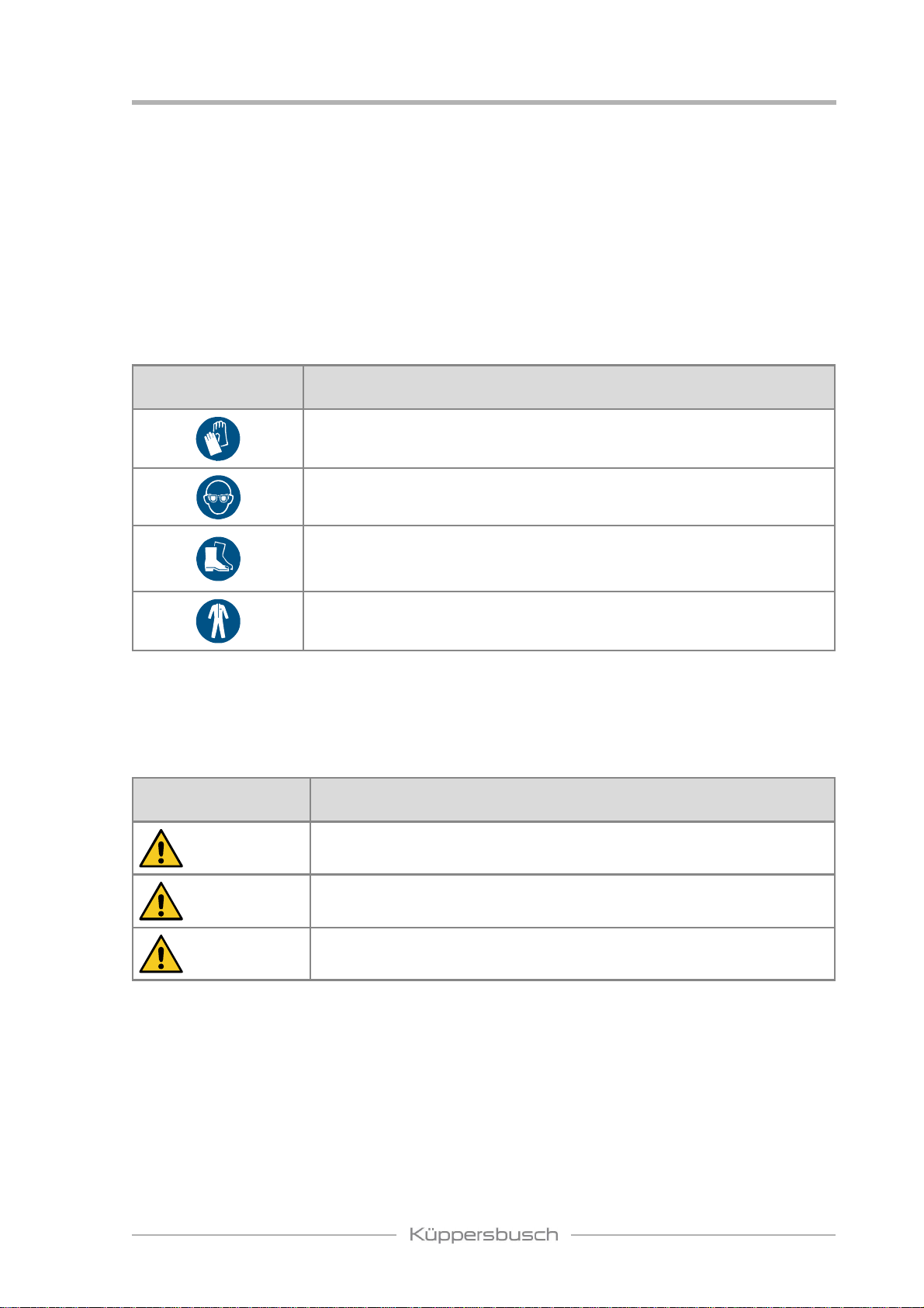
1.2 Personal safety equipment..................................................................................................4
1.3 Danger symbols..................................................................................................................4
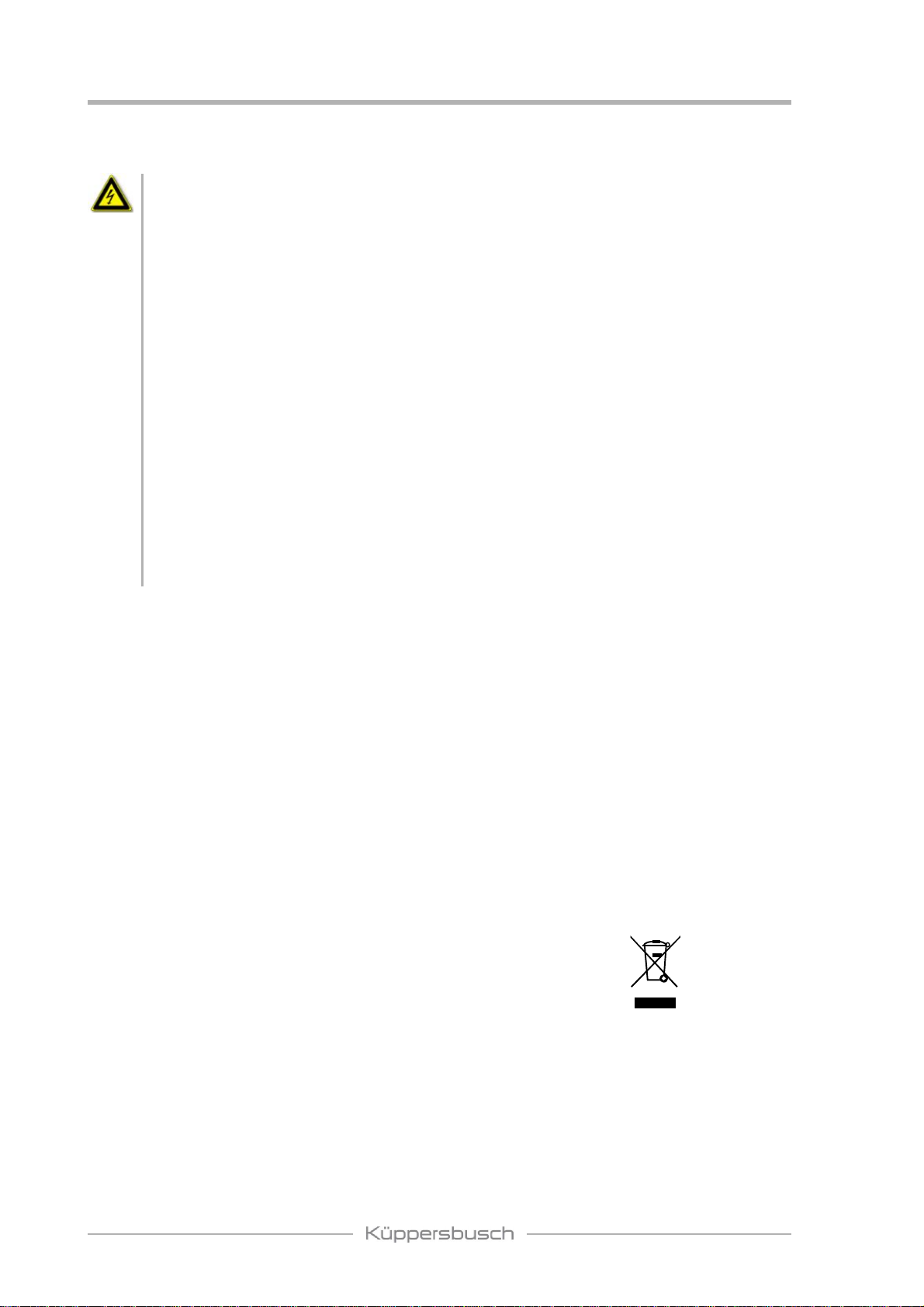
1.4 Electrical Safety..................................................................................................................5
1.5 Spare parts..........................................................................................................................5
1.6 Environmental protection....................................................................................................5
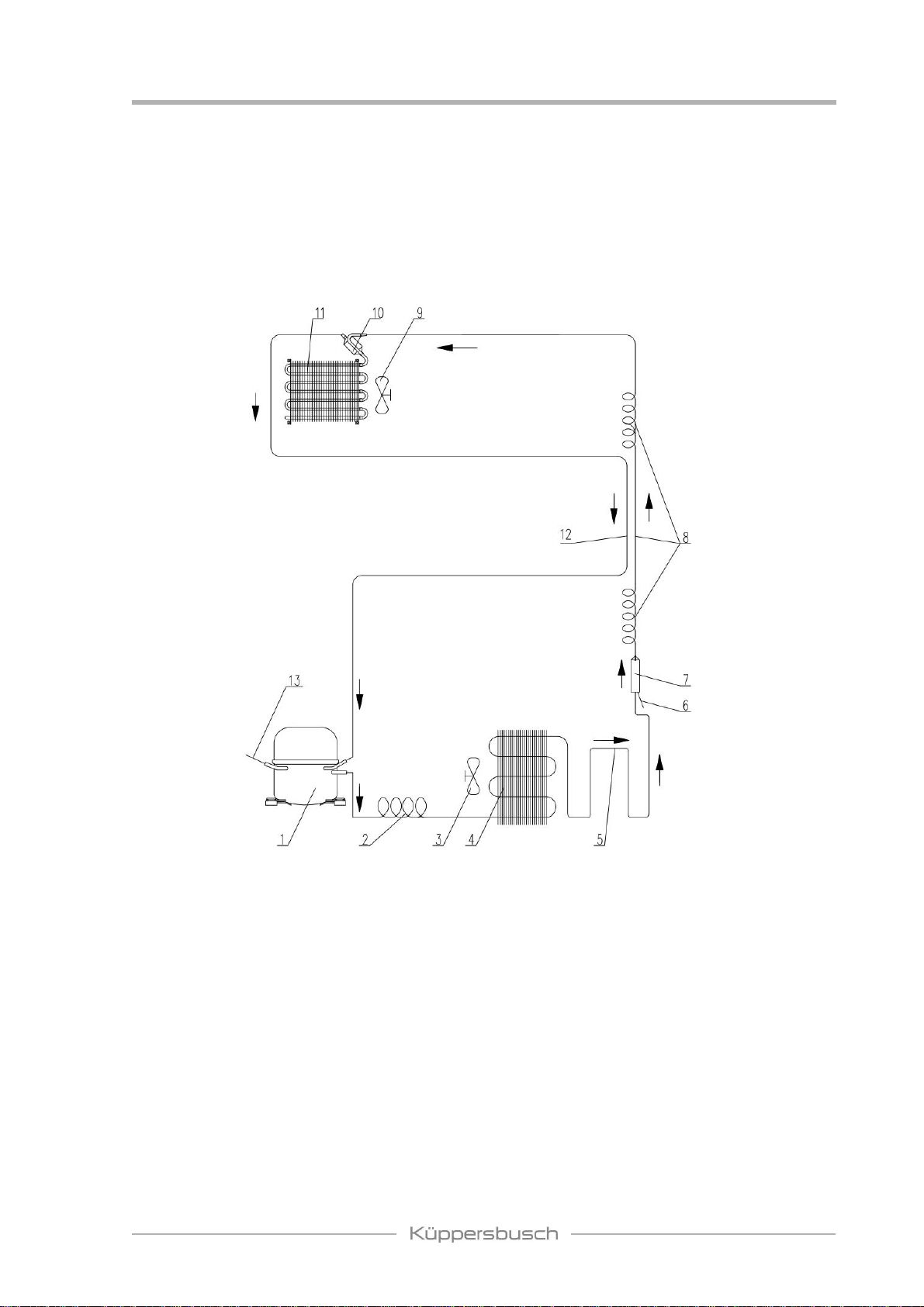
2 Refrigerant and cooling system .................................................................................6
2.1 Refrigerating cycle..............................................................................................................6
2.2 Refrigeration system...........................................................................................................8
3 Electrical and control systems ....................................................................................8
3.1 Control description..............................................................................................................8
3.2 Diagrams...........................................................................................................................13
3.3 Diagram for PCB...............................................................................................................15
3.4 Sensor resistance table.....................................................................................................16
4 Compressor room and parts list...............................................................................17
5 Doors............................................................................................................................18
5.1 Door stop...........................................................................................................................18
5.2 Door alignment..................................................................................................................20
5.3 Changing the door sealing................................................................................................20
5.4 Changing the LED Lamp...................................................................................................21
6 Replacing main parts..................................................................................................22
6.1 Control PCB, fan motor, ventilation flap and LED light in the middle divider ....................22
6.2 Replacing the power PCB.................................................................................................23
6.3 Evaporator fan motor and temperature sensor in the upper part of
dual-zones models............................................................................................................23
6.4 PTC heating, fan motor heating, temperature sensor in the lower part
of the dual-zones models..................................................................................................24
6.5 Evaporator fan motor, Temperature sensor and PTC heating in the
single zone models...........................................................................................................24
6.6 Evaporator fan motor and condenser................................................................................25
6.7 Evaporator group..............................................................................................................26
6.8 Compressor, PTC-starter and overload protector.............................................................26
6.9 Filter dryer.........................................................................................................................27
7 Troubleshooting..........................................................................................................27
7.1 Diagnosis guide.................................................................................................................29
7.2 Symptom diagnosis...........................................................................................................29
7.3 Troubleshooting in the refrigerant system.........................................................................31
7.4 Special detailed diagnosis.................................................................................................32
7.5 FAQ...................................................................................................................................40

4
Safety precautions
H8-93-01
1 Safety precautions
1.1 Qualification of the Technical Service Personnel
The repairs mustbe carried out by specialized personnel. Inappropriate repairs may cause
harm to the users.
1.2 Personal safety equipment
Mandatory signs Meaning
Protective gloves protect the hands from infections as well as from
slight bruises and cuts.
Protective glasses protect the eyes.
Safety shoes offer good slip resistance, especially in wet conditions
as well as a high penetration resistance (e.g. with nails) and protect
the feet from falling objects (e.g. during transport).
Protective clothing protect the hands from infections as well as from
slight bruises and cuts.
1.3 Danger symbols
Warnings of damage to persons are marked according to DIN EN 82079-1.
Warning symbols
and signal word Meaning
DANGER Note indicating an imminent high risk which may result in death or
very serious injury.
WARNING Note indicating an imminent medium risk which may result in death
or very serious injury.
CAUTION Note indicating a dangerous situation which may result in minor injury
or damage to the appliance.
Warnings of damage to property are marked with the signal word ATTENTION.

5
Safety precautions
H8-93-01
1.4 Electrical Safety
WARNING
Risk of serious or fatal injury from electric shock!
All parts of this appliance capable of conducting electrical current are grounded.
If grounding wires, screws, straps, clips, nuts or washers used to complete a path to ground
are removed for service, they must be returned to their original position and properly
fastened.
If grounding wires, screws, straps, brackets, nuts, or washers required for grounding have
been removed for service, they must be returned to their old location and properly fixed.
Disconnect the appliance from the mains prior to carrying out any repair work!
If electrical power is required for diagnostic or test purposes, disconnect the appliance from
the power supply immediately after performing the necessary checks.
When testing under voltage, be sure to use a residual current circuit breaker. The earth
connection must not exceed the standardized values. This is extremely important for the
safety of the people and functionality of the appliance.
The housing and the frame may be submitted to voltage in the case of a fault.
Do not touch any part inside the appliance; the electronic module could be subject to high
voltage.
After the repair, VDE 0701 tests, or tests according to the standards of the respective
country, must be carried out.
1.5 Spare parts
There are more and more copies of high-quality spare parts and additional components on the
market. With the naked eye plagiarisms are often indistinguishable from the original.
For counterfeit products, the problem lurks in detail: Parts are not hardened, corrosion
protection is missing orgasket and lubricant do not fulfilltheirpurpose. Instead ofa high quality
tempered steel, the manufacturer of the copies may have used only one (inferior) standard
steel for economic reasons.
The installation of unauthorized parts affects the safety and excludes a warranty by
Küppersbusch.
When replacing use only original parts.
1.6 Environmental protection
Electrical appliances and batteries must not be disposed of with
household waste. Observe regional waste disposal regulations for
the protection of the environment. Your dealer is obliged to take back
used electrical appliances and batteries.

6
Refrigerant and cooling system
H8-93-01
2 Refrigerant and cooling system
2.1 Refrigerating cycle
2.1.1 For models without solenoid valve
1. Compressor
2. Spiral tube (not available for some models)
3. Condenser fan (not available for some models)
4. Condenser (not available for some models)
5. Hot pipe
6. Process tube
7. Filter dryer
8. Capillary tube
9. Evaporator fan
10. Accumulator
11. Evaporator
12. Suction tube
13. Process tube

7
Refrigerant and cooling system
H8-93-01
2.1.2 For models with solenoid valve
1. Compressor
2. Spiral tube (not available for some models)
3. Condenser fan (not available for some models)
4. Condenser (not available for some models)
5. Hot pipe
6. Process tube
7. Filter dryer
8. Solenoid valve
9. Capillary tube
10. Evaporator fan
11. Accumulator
12. Evaporator
13. Suction tube
14. Process tube

8
Electrical and control systems
H8-93-01
2.2 Refrigeration system
All refrigeration units cool by removing heat from the cabinet rather than pumping in cool air.
In a conventional refrigeration unit, liquid refrigerant enters the evaporator and vaporizes
(boils) due to the low pressure, creating a very cold surface which removes heat from inside
the cabinet.This causes the refrigerant to boil(evaporate) into a vapor state and be drawn into
the compressor.
The compressor pressurizes the vapor and pumps it into the condenser. The hot vapor in the
condenser gives offthe heat into the room.
3 Electrical and control systems
3.1 Control description
3.1.1 Functions
Cooling mode
When the set temperature is lower than the storage temperature, the unit operates in cooling
mode.
Heating mode
When the set temperature is higher than the storage temperature, the unit operates in heating
mode.
Dynamic Climate/Silent modes
In the Dynamic Climate mode, the interior fan cycles on 20 seconds and off30 seconds to
circulate the inside air evenly until the set temperature is reached. Dynamic Climate mode is
NOT the factory preset mode because of creating noises and increased energy consumption.
To change to Dynamic Climate mode, touch and hold the DOWN key for approximately five
seconds. The wine cellar will beep five times to confirm Dynamic Climate mode is on. To
change back to default Silent mode (energy saving mode), touch and hold the UP key for
approximately five seconds. The wine cellar will beep three times to confirm default (Silent)
mode is on.
Eco Demo mode
By pressing and holding the UP and DOWN keys (the controls of lower zone for dual zone &
three zone models) and the LIGHT key at the same time for at least 5 seconds, the indicator
light will flash five times to confirm the input and the unit will operate in Eco Demo mode. The
indicators for Fahrenheit and Celsius degree will be ON. In Eco Demo mode, the compressor
and all fan motors are OFF.

9
Electrical and control systems
H8-93-01
Note: To perform the multi-key function, press and hold the first key, then press the other
keys the required number of times and then release all the keys.
Sabbath Mode
Sabbath mode is available for the observance of certain religious holidays.This mode turns off
the displays, interiorlight and audible alarms and prevents them from turning onagain. Normal
cooling operations will still take place.
To initiate Sabbath mode, press the POWER and LIGHT keys at the same time for at least
5seconds.The indicator light will flashfourtimesand confirmtheSabbathmodeisON.Sabbath
mode can be exited by repeating the above process. The Sabbath mode will automatically
switch offafter 96 hours.
3.1.2 Alarm system
Temperature display
During normal operation,the temperature displays on the control panelshow the temperatures
inside the appliance. The temperature display will flash if
• a different temperature is being set;
• the temperature in one of the zones deviates by more than 5°C from the set
temperature.
The temperature display flashing ensures that the temperature cannot rise or fall undetected
and impair the wine.
To view the set temperature at any time, touch the UP or DOWN mark. The set temperature
will temporarily flash in the LED display for 5 seconds.
If the LED readoutsdisplaythe icon “--" and flash, that means the display temperature is out of
the range of -9 to 37 ºC for Celsius or 16 to 99 ºF for Fahrenheit. This is normal.
Temperature alarm
An alarm will sound if the temperature in one of the zones rises or falls outside the temperature
range. The relevant temperature display will flash at the same time.
The temperature the appliance is set at determines the temperature the appliance recognises
as being too warm or too cool. The alarm will sound and the temperature display will flash:
•when you switch the appliance on, if the temperature inside the appliance is very
different from the temperature set;
•when there has been a lengthy interruption to the power supply;
•when too many items have been put into the unit at one time;
•when the door is not been closed tightly.

10
Electrical and control systems
H8-93-01
Door alarm
If the door has been left open for more than 60 seconds, the alarm will sound.
Once the set temperature has been reached in the appliance, the alarm stops and the relevant
temperature display stops flashing. However, if the noise disturbs you, you can switch the
alarm offbefore this if you wish by pressing the ON/OFF key once. The alarm will stop. The
relevant temperature display continues to flash until the set temperature has been reached.
The display then lights up constantly, and the alarm system is fully active again.
3.1.3 Other functions
Temperature memory function
In the event of a power interruption, the unit can remember the previous temperature settings,
and when the power is recovered, the unit will operate at the temperature whichwas set before
the power was interrupted.
Interior light
The interior light makes it easy to view your wine labels and enhances the display of your
collection. Touching the LIGHT mark toggles between 2 modes of operation for the internal
lights:
Default mode
If you are in functional (default) mode, the lights will turn on only when the door is open.
Showcase mode
If you are in showcase mode, the lights will be on whether or not the door is open.
Defrosting cycle
1. The defrosting is performed each time when the total running time of the compressor
reaches 10 hours.
2. During the defrosting cycle, the compressor is OFF and the fans will operate continuously.
3. After 30 minutes, the defrosting cycle will end.
4. During the defrosting cycle, the storage temperature may vary by 3 or 4 degrees. That
is normal.
5. However, the frost may be accumulated on the evaporator if the unit is
repeatedly opened in a high heat or high humidity location. If this frost pattern
does not clear within 24 hours, your unit will require manual defrosting.
Key lock
Key lock function is only available for models with outside control. If in 2 minutes
or longer without pressing any key, the key lock will be activated automatically.
To remove the lock, press the UP and DOWN keys at the same time for
at least 5 seconds and the indicator light will flash three times to confirm the input.
ºF/ºC selector
To change the temperature from Fahrenheit to Celsius or from Celsius to Fahrenheit, press
and hold the LIGHT key for 5 seconds.

11
Electrical and control systems
H8-93-01
3.1.4 Fan control
Fan F1C and F1H
•For single-zone models, the evaporator fan motors are positioned in the cabinet
inside. For dual-zone models, the fan motors are positioned in the upper zone. For
three-zone models, they are positioned in the middle zone.
•When the set temperature of upper zone is lower than the storage temperature,
fans 1C & F1H will operate. For the rest of the time, fans F1C & F1H will cycle on
20 seconds and off30 seconds to circulate air inside the cabinet.
•For single-zone models with heating function, fans 1C & F1H will operate when the
heater is ON.
Fan F2C
•Only available in the models with dual-zone or three-zone functionality.
For dual-zone models, F2C is positioned in the middle divider. For three zone
models, F2C is positioned in the door divider.
•When theset temperature of the lower zone islowerthan the storage temperature,
fan F2C will operate.
•When the set temperature of upper zone for dual-zone or the middle zone for
three-zone models is higher than the storage temperature, fan F2C will operate.
•At the rest time fan F2C will be OFF.
Fan F2H
•Only available in the models of dual or three zones. For dual-zone and three-zone
models, F2H is positioned in the bottom zone.
•When the set temperature of upper zone is higher than the storage temperature,
fan F2Hwill operate. For the rest of the time, fan F2H will cycle on 20 seconds and
off 30 seconds to circulate air inside the cabinet.
Fan F3C
•Only available in three-zone models. The fan is positioned in the top divider.
•Whenthesettemperatureoftheupperzoneishigherthanthestorage temperature,
fan F3C will operate.
•For the rest of the time, fan F3C will be OFF.
Fan F3H
•Only available in three-zone models. The fan is positioned in the top divider.
•When the set temperature of upperzone is lower than the storage temperature, fan
F3H will operate. For the rest of the time, the fan will cycle on 20 seconds and off
30 seconds to circulate air inside the cabinet.
Fan F0
•Only available in built-in models. When the compressor is ON, fan F0 will be ON
too. The rest of the time, fan F0 will be OFF.

12
Electrical and control systems
H8-93-01
3.1.5 Self-checking function of the control system
The display/control PCB has a self-checking function. Press and hold the LIGHT and DOWN
keys at the same time for 5 seconds, the indicator light will flash once to confirm the input
and the unit will activate the self-checking program. The display lights up constantly and the
automatic checking program will start. Below symptoms can be seen, otherwise replace the
PCBs. •LED indicators will be ON one by one.
•LED light will be ON.
•Temperature reader LED will display from 00 to 99.
•Fan motor, compressor and heater will be ON.
After the self-checking program has finished, the unit will automatically go into the normal
operation program.
3.1.6 Test mode
Press and hold the LIGHT and UP keys (the controls of upper zone for dual-zone models and
the controls of lower zone for three-zone models) keys at the same time for 5 seconds with
powerON, the indicator light will flash twice to confirm the input and the unit will run in the Test
mode. The compressor and all fan motors will operate continuously and iindependently of the
set temperature. At the same time the display shows “--". The TEST Mode will automatically
stop after 30 minutes or you can stop the Test mode by disconnecting the unit from power
source.

13
Electrical and control systems
H8-93-01
3.2 Diagrams
3.2.1 For single-zone models
3.2.2 For freezer models

14
Electrical and control systems
H8-93-01
3.2.3 For dual-zone models with solenoid valve
Control panel inside the cabinet
3.2.4 For three-zone models

15
Electrical and control systems
H8-93-01
3.3 Diagram for PCB
3.3.1 Power PCB
3.3.2 Control PCB for dual-zone models and upper control unit for three-zone
models

16
Electrical and control systems
H8-93-01
3.4 Sensor resistance table
• The tolerance of sensor resistance is ±5%
• Be sure to measure the sensor resistance after keeping the sensor more than 3 minutes at
a measuring temperature (delay due to sensor speed).

17
Compressor room and parts list
H8-93-01
4 Compressor room and parts list
1. Connection of condenser outlet tubing and hot pipe inlet tubing
2. Electrical box
3. Process tube
4. Power PCB
5. Compressor
6. Suction tube
7. Discharge pipe
8. Condenser fan motor (not available in some models)
9. Drainage hose
10. Outlet tubing of hot pipe
11. Process tube
12. Dryer
13. Capillary tube
14. Water drip tray
15. Levelling leg
16. Compressor base
17. Compressor leg
18. Power supply cable with plug

18
Doors
H8-93-01
5 Doors
5.1 Door stop
This door opening is from either the left or right side. The appliance is delivered to you with the
door opening from the left side. To reverse the door stop, please follow the instructions:
Note: All parts removed must be saved for the reinstallation of door.
5.1.1 Built-under appliances
1. Remove the ventilation grill (2) and the adjustable ventilation grill (1) by unscrewing the
screws (3) and (4).
Note: For some models without adjustable ventilation grill, the step is not needed.
2. Gently pull down to remove the glass door from the right top hinge and
3. place it on a soft surface to avoid the risk of damage.
4. Then remove the right top hinge (9). (Fig. 4)
5. Remove the bottom hinge (5) by unscrewing the four lock screws (6). Be careful to hold the
glass door firmly after removing the screws. (Fig. 2)
6. Unscrew and transfer hinge pin (7) and/or door stopper (8) of the bottom hinge to the
opposite side. (Fig. 3)

19
Doors
H8-93-01
7. Remove the cover caps on the left side of cabinet and use them to cover the screw holes
on the right-hand side.
8. Screw the alternative left top hinge (11) with the fittings on the left side of the appliance (Fig.
4).
9. Unscrew and the locking bracket and screw it to the opposite side of glass door. Then use
the crystal cover (12) as a part of the fittings to cover the three holes left after unscrewing
the lock bracket. (Only for models with lock on the ventilation grill.) (Fig. 5)
10.Rotate the door 180° (with lock on the door) and relocate the door to the designated
position. Then screw the bottom hinge assembly on the left position and tighten it after the
door is levelled.
11. Fix all the handles and plugs at the opposite side and reassembly the ventilation grills if
necessary.
5.1.2 Built-in appliances
1. Remove the glass door by unscrewing the eight locking screws (3) and (4). Be careful to
hold the glass door firmly after removing the screws and place it on a soft surface to avoid
risk of damage.
2. Unscrew and the hinge (2) and screw it to the opposite side of glass door.
3. Rotate the door 180° and install the door at the opposite side. Then screw and tighten it
after the door is levelled.

20
Doors
H8-93-01
5.2 Door alignment
1. Tilt the appliance together with another person and loosen the screws (2).
2. Align the glass door with the top side parallel to the top of the cabinet, and then tighten the
screws.
3. An adjustment of the hinge is necessary if:
4. The door sealing along the hinge side of the door does not adequately seal.
5. The door sealing on the hinge side is squeezed more than 1/16 inch (1.5 mm) (which can
result in poor sealing at other places on the top).
6. The distance between the door and the cabinet at the top is greater than at the bottom or
vice versa.
7. Ifat leastoneof theseconditions istrue, thehinges must be adjustedto correcttheproblem.
By lifting the hinges, a sagging of the door can possibly be remedied.
5.3 Changing the door sealing
1. Open the door and remove the old door sealing (2) from the door frame (1) by pulling out
the gasket.
2. Attach the new door seal to the door frame. Be careful not to damage the door or door
sealing.
This manual suits for next models
2
Table of contents
Other Kuppersbusch Wine Cooler manuals