Kurt 3800H Series Instruction Manual

3800H-Series Vise
“Hydraulic” Base
Assembly
3800H-Forward
3810H- Reverse
Operating Instructions Manual
ENGLISH

2ENGLISH |
Table of Contents
Introduction .................................................................................................................3
Installation & Assembly Guide...........................................................................4-5
3800H Parts List...........................................................................................................8
3800H Mechanical Drawing ...................................................................................9
3810H Parts List........................................................................................................10
3810HMechanicalDrawing...................................................................................11
Maintenance Schedule.....................................................................................12-15
HydraulicSet-up..................................................................................................16-17
Troubleshooting Tips ............................................................................................. 18
Vise Data
Use this to ll out information about your vise for quick reference.
Purchase Date: _______ -_______-_______
Purchase Order: _______________________
Purchased From: _______________________
Delivery Date: _______________________
Serial No.: _______________________
Note:
Make sure to register your warranty online at kurtworkholding.com
Table of Contents

3ENGLISH |
Introduction
Thank you for purchasing a Kurt vise. The Versatile Lock
3800H-Series AngLock vise has a time proven design and
the outstanding accuracy of this product is second to none.
Backed by a lifetime warranty, this product will last many
years when used and maintained properly.
The original Kurt Anglock vises are designed for precision
clamping. The “Pull-type” action of the 3800 Versatile Lock design
reduces stationary jaw deection by at least 80%. This vise
has a one-piece body and stationary jaw design which reduce
weight and increases strength while providing .0005 clamping
repeatability. It oers ultra-high precision through many
important features. Features include: Ground sides that allow side
mounting, upright and back to back mounting, using the body
through holes allows side by side mounting.
With four dierent models including standard and reverse in both
manual and hydraulic conguration these vises are truly versatile.
The patented Anglock design allows the movable jaw to
advance in such a way that each pound of force forward induces
a ½ pound force downward which minimizes the jaw lift and
increases accuracy. This combined with the needle bearings
increases jaw clamping pressure. Other features include: 80,000
psi ductile iron body, hardened vise bed & case hardened jaw
plates, semi-hard steel screw.
Introduction

4ENGLISH | Installation & Assembly
Installation & Assembly Guide
Now that you have your new Kurt 3800H-Series vise, it’s time to set-up
and begin using it. You will see that your new vise comes with a Kurt
swivel handle,two chip guards (short & long)supplied in the shipping
carton. e chip guard rests between the ways of the vise and can be
trimmed to size to help keep chips out of the screw. e handle is
specically designed to provide maximum torque to your vise. Your vise
should be mounted to a clean at surface. e surface and the vise must
be free of any chips, dirt or debris of any kind. e mounting surface can
be honed if necessary. Clean the bottom of the vise with solvent or other
cleaner if needed.
Hydraulic activated vises require power. is could be done with a single
acting hydraulic pump (air over oil). You can purchase one through Kurt
or through another supplier. (See Hydraulic Set-up in the back of this
manual)
To minimize vise bed deection, clamp your Kurt vise to your machine
table, pallet, or sub-plate using the built-in clamping slots provided.
To access the through holes, simply pick the edge of the protective cap
up and expose the counter bored hole. Replace the cap aer you have
mounted the vise to keep debris out of the holes. If you are mounting the
vise on it’s side or back to back, other clamping methods may be required.
Hydraulic Press Clamping Force (LBS)
500 1500
1000 3000
1500 4500
2000 6000
2500 7500
3000 9000
3200 11,000
Hydraulic Vise Clamping Force
Hydraulic displacement cu. In. 1.82

5ENGLISH | Operating Instructions
Additional clamping can be used, but may not be necessary.
Please be sure to exercise good judgment when securing your
vise to the mounting surface. Be sure your vise is secured and
will not move when applying the machine pressure.
Operating Instructions
For proper vise operation place the handle on to the hex end of
the vise. Rotate clockwise to clamp and counterclockwise to un-
clamp your vise. is handle combined with the correct amount
of torque will provide you with all the clamping force you will
need to machine your parts. A high quality calibrated torque
wrench can be used if needed.
DO NOT use any other type of pressure to open or close your
vise.
e uses of handle extensions, air impact wrenches, breaker
bars or hammer strikes are not recommended and will void
the warranty if used. is will also cause damage to the thrust
bearing and screw threads. If you need more clamping force you
may need to upgrade to a larger vise.
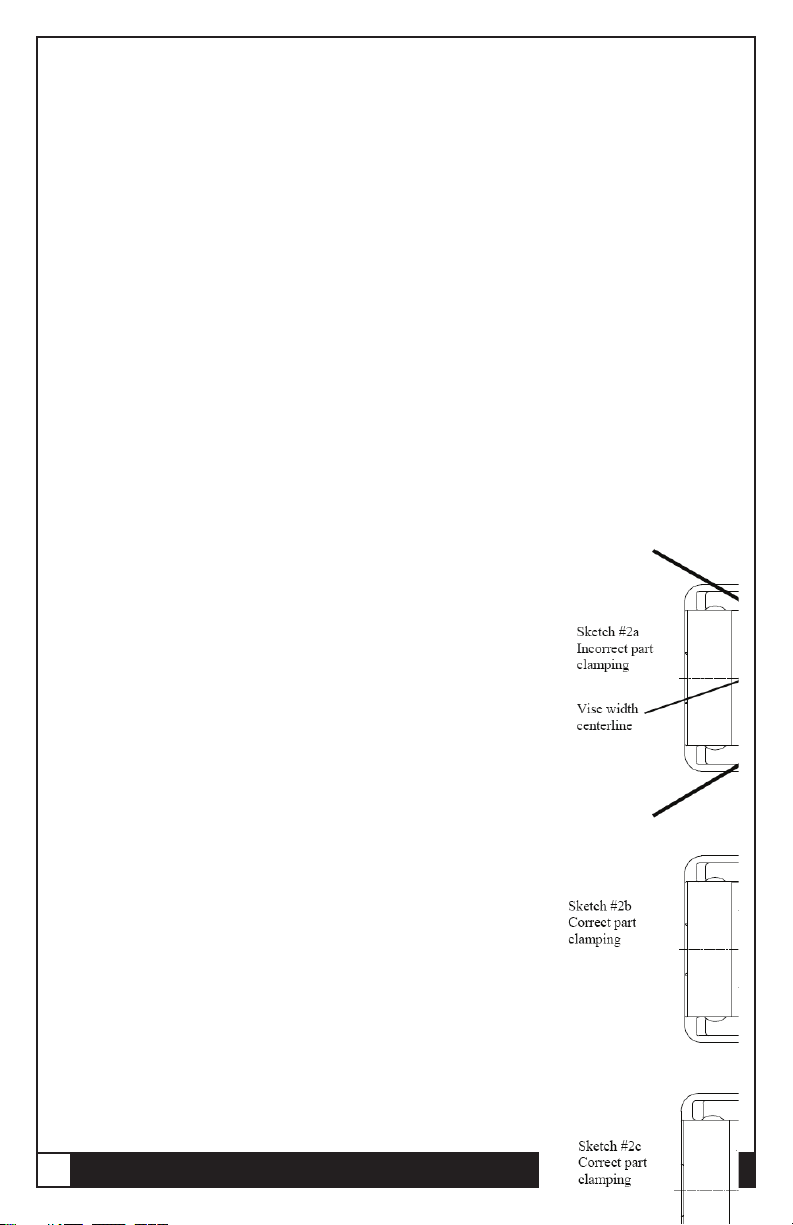
To properly clamp a part in your Kurt vise you should place
the part in the center of the jaws resting on the ways of the vise.
Clamping only on one side or above the movable and stationary
jaws can result in jaw li or loss of accuracy. (See Fig. on next
page)
If one-sided clamping is necessary you MUST use a dummy part
on the other side. When using parallels or step jaws you must se-
lect a size that keeps the bottom of the clamped part at or below
the top of the movable and stationary jaws. Always use jaw plates
for clamping. If jaw plates are not used,the mounting surface of
the movable and stationary jaw will be damaged. is will result
in reduced clamping accuracy and repeatability.

6ENGLISH | Operating Instructions

7ENGLISH |
Maintenance Log/Notes:
Maintenance Log/Notes

8ENGLISH | Parts list
3800H Parts List
ITEM# PART# DESCRIPTION QTY
1 3800V-1 BODY,MACHINED 1
2 3800H-5 SCREW 1
3 3800V-2 MOVABLE JAW 1
4 3800V-3 NUT 1
5 3800V-111 KURT LOGO TAF
6 PT800-211 BRUSH SEAL 2
7 3800V-99 O-RING #121 1
8 01-3278 SHSS CONE PT. 1/4-20X.75LG 1
9 8BHU 8” BASIC HYDRAULIC UNIT 1
10 D80-42 THRUST WASHER 2
11 D80-41 THRUST BEARING 1
12 3800V-128 O-RING 224 4
13 3800V-8 2-PIECE RETAINNING NUT 1
14 00-1197 SHCS 8-32 X .75LG 4
15 00-1481 SHCS 5/8-11X1.25LG 4
16 D80-7 JAW PLATE 2
17 3800V-191 PROTECTIVE PLUG 2
18 DL430-68 O-RING #022 2
19 D80-9 SEGMENT 1
20 01-3953 HDOG SHSS 5/8-11X1.25LG. 1
21 3800V-147 RETAINING RING 2
22 3800V-224 SCREW SUPPORT 1
23 3800H-102 MODEL/SERIAL TAG 1
24 07-0230 U-TYPE DRIVE SCREW 2
25 D80I-10-SA 8”HANDLE ASSEMBLY 1
26 D80XL-248 CHIP GUARD 1
ITEMS 5,23,24,25,26 ARE NOT SHOWN ON THE DRAWING.

9ENGLISH | 3800H Mechanical Drawing
3800H DRAWING

10 ENGLISH |
ITEM# PART# DESCRIPTION QTY
1 3800V-1 BODY,MACH 1
2 3810H-5 SCREW 1
3 3800V-2 MOVABLE JAW 1
4 3810V-3 NUT 1
5 3800V-111 KURT LOGO TAF 2
6 PT800-211 BRUSH SEAL 2
7 3800A-99 O-RING #121 1
8 01-3278 SHSS CONE PT. 1/4-20 X .75LG 1
9 8BHU 8” BASIC HYDRAULIC UNIT 1
10 D80-42 THRUST WASHER 2
11 D80-41 THRUST BEARING 1
12 3800V-128 O-RING#224 1
13 3800V-8 2-PIECE RETAINING NUT 1
14 00-1197 SCHS 8-32X .75LG 6
15 00-1481 SHCS 5/8-11 X 1.25LG 4
16 D80-7 JAW PLATE 2
17 3800V-191 PROTECTIVE PLUG 2
18 DL430-68 O-RING 022 2
19 D80-9 SEGMENT 1
20 01-3953 HDOG SHSS 5/8-11-XX 1.25LG 1
21 3810H-102 MODEL/SERIAL TAG 1
22 07-0230 U-TYPE DRIVE SCREW 2
23 D80I-10-SA 8”HANDLE ASSEMBLY 1
24 D80XL-248 CHIP, GUARD 1
ITEMS 5,21,22,23,24 ARE NOT SHOWN ON THE DRAWING.
3810H Parts List
Parts list

11 ENGLISH |
3810H DRAWING
3810H Mechanical Drawing

12 ENGLISH |
Maintenance Schedule
It is very important to perform regular maintenance on your
Kurt vise to assure proper operation. Improper maintenance
will result in poor vise performance and may void your war-
ranty.
Daily/ Weekly
1. Remove chips from surface of vise.
2. Visually inspect for chips, seals for damage and cleanliness.
3. Visually inspect for chip entrapments and remove when
necessary.
4. Air-dry and apply rust inhibiting oil to the machined sur-
face of the vise.
Monthly
1. Open the vise to the maximum opening.
2. In the back of the movable jaw (handle end, center hole)
loosen the socket head set screw (approx. 6 turns) With the
hex key (Allen wrench) in the set-screw socket li up and
forward to pivot the jaw o of the vise bed.
3. Slide the Jaw slightly toward the stationary jaw and li up to
remove the jaw from the “hook” of the nut. Note: A spherical
segment (shaped as ½ of a steel ball) is inside the cavity of the
movable jaw and may fall out as the jaw is removed. Take care
not to lose or misplace the spherical segment.
4. Turn the movable jaw over and clean the inside cavity. Also
clean the spherical segment.
5. Remove chips, clean and apply a light coat of machine oil to
the machined surface of the following items:
a. Nut and Screw assembly (clean exposed threads on
the screw).
b. Bed of vise (top of “rails”)
c. Inside of the vise between the center ways.
Maintenance Schedule

13 ENGLISH |
6. To re-assemble the movable jaw, apply a “glob” of grease to the
under side of the movable jaw in the pocket. Place the spheri-
cal segment in the mating pocket and push into the grease. e
grease will hold the segment in place when the jaw is turned over
to replace.
7. Tip the jaw so the front of the jaw (the side with the jaw plate)
is on the vise bed. Lower the jaw on to the bed so that the seg-
ment contacts the hook part of the nut and rest the jaw on to the
vise bed.
8. Tighten the setscrew to rmly contact the nut. Back o the
setscrew ¼ turn (approx.) note: DO NOT leave the setscrew tight-
ened rmly to the nut as this may cause improper operation. e
movable jaw is designed to move slightly (pivot side to side) so
maximum jaw plate contact is maintained when clamping out-of-
parallel, sawed, or cast parts.
9. Your vise is now ready for use. Open and close your vise to
check for proper operation. Center the part to be clamped in the
vise and close. Your parts should be centered from side to side to
insure proper clamping. (See Fig. below)

14 ENGLISH |
3 to 6 months
1.Open vise to maximum opening.
2.Loosen and remove the movable jaw.
3.Remove spiral-retaining ring from handle end of the vise
screw.
4.Remove the screw support from the vise body.
5.Remove the two-piece locking collar by removing the four
SHCS.
6.With one screw still half way out spin o the rst collar.
7.Using a pin or screw reach into the second collar and spin it
o exposing the bearings.
8.Remove the thrust bearing assembly consisting of (2) thrust
washers and (1) thrust bearing from the counter bore
in the end of the body.
9.Clean and inspect the counter bore, thrust washers and
thrust bearing.
10.Apply water resistant grease to the thrust washer
(i.e.marine grade grease)
11.Install thrust bearing assembly on the screw in the reverse
manner.
12.Install the rst collar by spinning on the screw until it
stops. (Items 12-14—See Fig. 1)
13.Install the second collar behind the rst and spin on until
it stops. At this point the screw holes may or may not
be lined up.
14.Turn the second collar counterclockwise until a hole lines
up.
Fig. 1
Fig. 2
Maintenance Schedule

15 ENGLISH |
15.en turn the collar back TWO (2) more screw holes. is
will allow proper distance for the collar to lock on the
threads and keep the bearings rmly in place. (Items
15-16—See Fig. 2)
16.Install the four SHCS and tighten.
17.Install the screw support in the body on the screw (Hex
end).
18.Your vise is now ready to use.
Hydraulic Set-up
8 BHU Basic Hydraulic Unit

16 ENGLISH |
Hydraulic Set-up
e 3800H/3810H Series Hydraulic vises use the KHP5000PF or
KHP5000PH Hydraulic Pump.
1. Remove plastic caps from pressure and release ports on Hydraulic
pump. Install 90° ttings.
2. Remove plastic caps from pressure and release ports on hand or
foot valve. Install straight tting.
3. Install straight tting on the Hydraulic Unit (1/8 NPTF)of the
3800H/3810H vise.
4. A lter-lubricator-regulator (KHP5000PF-KIT see g. 3) combina-
tion is recommended to insure clean air coming into the unit. See
Clamping Force Chart for air pressure required to attain desired
clamping force.
5. Connect the FRL to the input air port on the rear of the
KHP5000PF/PH hydraulic pump. See g.4 & 6.
6. Connect the hydraulic line to the hydraulic unit on the vise and
then to the output side of the hydraulic pump g.4
7. If using a hand valve connect the 3-line cluster g.5 & 6.
8. Apply air pressure (80 PSI maximum) to system. Loosen swivel t-
ting at vise and bleed air. Tighten tting. Release air pressure.
9. Repeat previous step until all air is purged
10. e KHP5000PF/PH hydraulic will come pre-lled with oil (use
#13 or DTE lite if needed)
11. System is now ready for use.
NOTE: For multiple vise hook-ups, call factory for recommendations.
Fig. 3
KHP5000PF-KIT
Hydraulic Set-up

17 ENGLISH |
Fig. 4
Hand Valve connection
Fig.6
Fig. 5
Hydraulic Set-up

18 ENGLISH |
Troubleshooting Tips
The Kurt 3800H-Series vise will operate trouble free for many
years, if properly maintained. In some cases it will be necessary to
troubleshoot. Use the information below to help in the process.
Problem: My vise turns hard.
Tip: As a new vise the brush seal could be sti. Allow for break in of
vise.
Tip: As a used vise, it could be led with chips and threads could be
jammed. Properly clean and grease vise.
Problem: The collar comes o.
Tip: Retighten the four SHCS that hold it on. Proper adjustments need
to be made. See the 3-6 month maintenance schedule.
Problem: The handle support is loose or comes o.
Tip: You may need a new retaining ring. This support will oat, this is
normal. Install a new snap ring if needed.
Problem: My vise will not turn in either direction.
Tip: The vise is jammed with debris. Disassemble and clean as needed.
Problem: My vise won’t hold tolerance.
Tip: You may be experiencing jaw lift from clamping too high or on
one side of the jaw. Lower the part in the vise jaw and clamp more
material.
Troubleshooting tips

Troubleshooting Tips
All Kurt Manufacturing Company industrial workholding products and parts with the
exceptions noted below, are warranted against defects in material and workmanship
for the life of the product or part. (The life of the product is dened as that point in
time when such item no longer functions due to normal wear and tear.) Failure to
properly maintain and/or properly operate the product or part that has been worn
out, abused heated ground or otherwise altered, used for a purpose other than that
for which it was intended, or used in a manner in consistent with any instructions
regarding its use. The sole obligation of Kurt Manufacturing Company, Inc. (Kurt)
and the purchaser’s SOLE AND EXCLUSIVE REMEDY hereunder, shall be limited
to the replacement or repair of any Kurt product or part (by an authorized Kurt
technician) which are returned to Kurt Manufacturing Company’s place of business,
transportation, shipping and postal charges prepaid, and there determined by Kurt
Manufacturing Company to be covered by the warranty contained herein.
THE LIMITED WARRANTY DESCRIBED HEREIN IS MADE EXPRESSLY IN LIEU OF ANY
OTHER EXPRESSED OR IMPLIED WARRANTIES, INCLDING ANY IMPLIED WARRANTY OF
MERCHANTABLITY OR FITNESS FOR A PARTICULAR PURPOSE. KURT MANUFACTURING
COMPANY IS NOT RESPONSIBLE FOR THE IMPROPER USE OF ITS PRODUCTS.
KURT SHALL NOT BE LIABLE FOR ANY DIRECT, INDIRECT, INCIDENTAL SPECIAL OR
CONSEQUENTIAL DAMAGES, INCLUDING BUT NOT LIMITED TO, LOSS OF USE, REVENUE
OR PROFIT.
KURT ASSUMES NO LIABILITY FOR, AND MAKES NO WARRANTY REGARDING ANY
PURCHASE ITEMS WHERE THE MANUFACTURER OF SUCH ITEM EXTENDS A SEPARATE
WARRANTY.
9445 East River Road NW
Minneapolis, MN 55433
Phone: 877-226-7823
Fax: 877-226-7828
kurtworkholding.com Manual Revision: 11.01.2014

20 ENGLISH |
Thank you for your purchase!
If you have any feedback or questions.
Please contact us at:
or
1-877-226-7823
Like, Tweet, and Subscribe to us!
This manual suits for next models
2
Table of contents
Other Kurt Power Tools manuals