3
3 | ENLGISH
Table of Contents
Introduction .................................................................................................................3
Setup Instructions......................................................................................................4
Operating Instructions .........................................................................................5-7
DX6 Parts List ...............................................................................................................8
DX6 Mechanical Drawing........................................................................................9
Maintenance Schedule....................................................................................10-12
Troubleshooting Tips............................................................................................. 13
Vise Data
Use this to ll out information about your vise for quick reference.
Purchase Date: _______ -_______- _______
Purchase Order: _______________________
Purchased From: _______________________
Delivery Date: _______________________
Serial No.: _______________________
Note:
Make sure to register your warranty online at kurtworkholding.
Introduction
Thank you for purchasing a Kurt DX6 vise. You have just purchased one
of the best machine vises in the industry. The outstanding accuracy
of this product is second to none. Backed by a lifetime warranty, this
product will last forever when used and maintained properly.
The original Kurt Anglock vises are designed for precision clamping on
basic machine tools such as knee-type mills, grinders and machining
centers. They can be used for, but are not limited to, operations like
precision boring, drilling, tapping, grinding & nishing.
The patented Anglock design allows the movable jaw to advance in
such a way that each pound of force forward induces a ½ pound force
downward which minimizes the jaw lift and increases accuracy. This
combined with the needle bearings increases jaw clamping pressure.
Other features include: 80,000 psi ductile iron body, hardened vise bed
& jaw plates, semi-hard steel screw.
Table of Contents Introduction
INTRODUCTION
Thank you for purchasing a Kurt 3800H. You have just purchased one
of the best machine vises in the industry. The outstanding accuracy of this
product is second to none. Backed by a lifetime warranty against
workmanship and material defects, this product is built to last when used
and maintained properly.
The original Kurt Anglock vises are designed for precision clamping on
basic machine tools such as knee-type mills and machining centers. They
can be used for, but are not limited to, operations like precision boring,
drilling, tapping, & finishing.
The patented Anglock design allows the movable jaw to advance in such a
way that each pound of force forward induces a ½ pound of force
downward which minimizes the jaw lift and increases accuracy. This,
combined with the needle bearings, increases jaw clamping pressure.
Other features include: 80,000 psi ductile iron body, hardened vise bed &
jaw plates, and a semi-hard steel screw.
INTRODUCTION
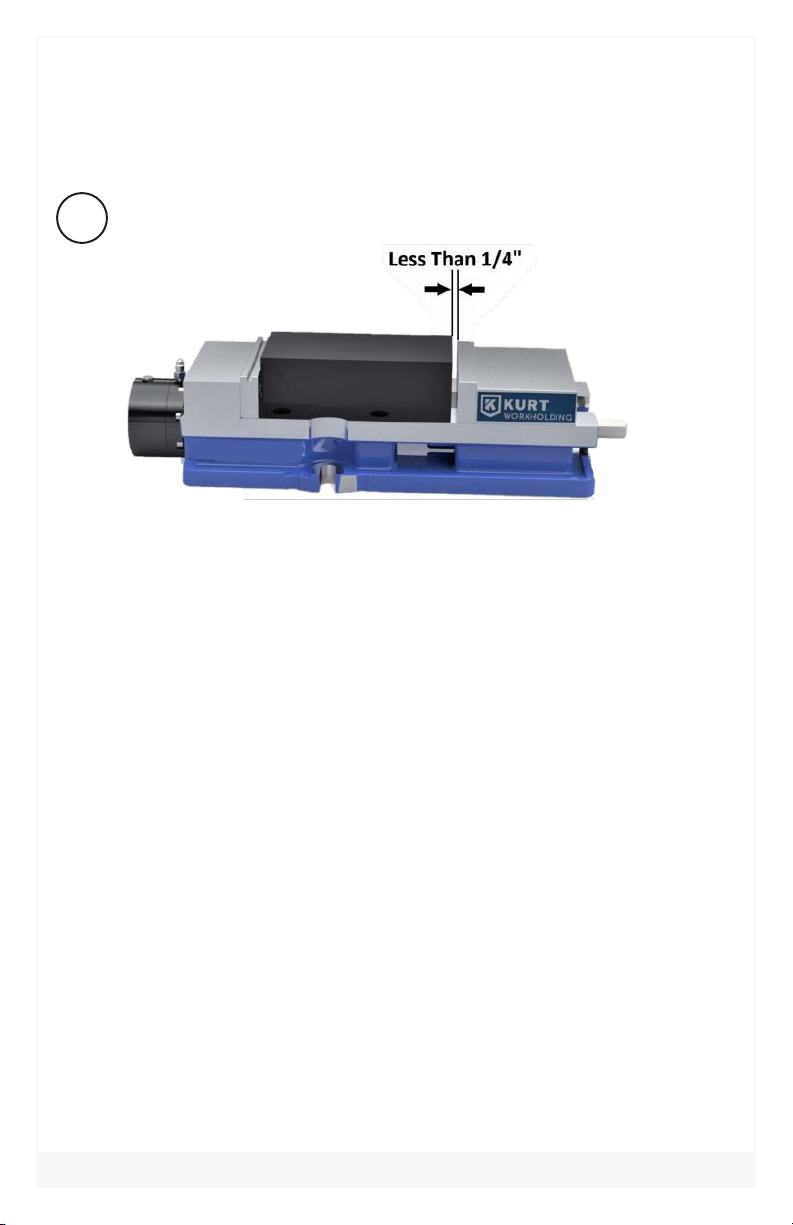
Fig.1