Kurth KE3700 Product information sheet

Version 018.002.002
© KURTH ELECTRONIC GmbH
All rights reserved, including those of the translation
Reprint and data processing, also in extracts, only with written permission
of Kurth Electronic GmbH
All trademarks and logos mentioned herein belong to their registered owners
KE3700
KE3550
xDSL MultiTest
Short user guide
Kurth Electronic GmbH | Muehleweg 11 | D 72800 Eningen u.A. GERMANY |
Tel. +49(0)7121 9755 0 | Fax +49(0)7121 9755 56 |

© Kurth Electronic GmbH, All Rights Reserved
2
Application
The KE3700 / KE3550 is a fast, easy to use and cost-eective multitester
for installing and troubleshooting DSL services in hybrid ADSL1/2/2+ / VDSL2
and bundled networks. With its variety of interfaces, it supports broadband
network technologies such as vectoring, G.fast, bonding, SHDSL*, Gigabit
Ethernet and GPON*.
Usage
The KE3700 / KE3550 provides powerful fault diagnosis for immediate trou-
bleshooting in the network, outdoor cabling, customer devices or indoor
cabling. Even in hybrid networks, where FTTH is also installed, measure-
ments can be performed on any LAN port using the Ethernet ports of the
KE3700 / KE3550. Therefore, the KE3700 /KE3550 is the ideal solution for
many broadband technologies.
Operation
With its small dimensions, robust design and intuitive operation, it is the per-
fect tester for installers and service technicians. Automatic recognition of the
xDSL service and denable test procedures enable the user to complete his
orders quickly and eciently. The large display increases the ease of use and
when saving the results, the technician has options for exporting the tests
and compiling reports.
At a glance
Multitasking tests without loss of synchronization
ADSL-VDSL2, G.fast and bonding in one device
Annex A/B/J/L/M with automatic xDSL detection
VDSL2 vectoring (ITU-T G.993.5)
Web browser
GbE port for advanced Ethernet testing
Modem / router and terminal mode
IP ping, traceroute with IPv4 (IPv6 ready)
FTP-Up/Download-Test, HTTP-Downloadtest up to 700 MBit/s
Sunlight readable colour TFT
High-performance battery
Including software for administration and protocols
Integrated Wi-Fi (* KE3700 only)

© Kurth Electronic GmbH, All Rights Reserved 3
Documentation and software
Current operating instructions and software updates can be found at
www.kurthelectronic.de in our download area. Under Service and Sup-
port > Downloads you will nd the corresponding les such as current
rmware and operating instructions for downloading.
PON/PTB*
(* KE3700 only)
200+ Mb/s
ADSL2+
~6-25 Mb/s
VDSL2
~50 Mb/s
CENTRAL
OFFICE
DSLAM CCB
FTTN
DSLAM CCB
VDSL2
VECTORING
~100 Mb/s
VDSL2
VECTORING
~100 Mb/s
VDSL2
G.fast
~500 Mb/s
VDSL2
BONDING
~100 Mb/s
Fibre
Copper
DSL Bonding
VDSL2
ADSL2+
Dark Fibre
xDSL Test
Ethernet Test
STB
STB
STB
STB
TV
TV
TV
TV
VoIP
VoIP
VoIP
VoIP
PC
PC
PC
PC
Fields of application

© Kurth Electronic GmbH, All Rights Reserved
4
ESC
12
ABC 3
DEF
0 #
5
JKL
4
GHI 6
MNO
8
TUV
7
PQRS 9
WXYZ
F1 F2 F3 F4
SHIFT
VIEW
SPKR
VOL
HELP
ON-OFF
SEL
UnfreezeFreeze
QR-Code
Keypad / Display / Connections
Ethernet 10/100/1000 Management,
Ethernet 10/100/1000 Test port, USB 2
ISDN analogue interface, SFP port*
xDSL test port, power supply connection
Wi-Fi antenna (optional)
Status LEDs
Speaker (Telephony)
Battery indicator
Sunlight readable TFT colour display
Connection: USB 1
optional KECT interface
Menu-sensitive function keys F1 – F4
Menu UP - DOWN / LEFT- RIGHT buttons
ON / OFF button
Microphone (Telephony)
Alphanumeric keypad
ESC (back) button
Select (enter) button
Status LEDs (* KE3700 only)
DSL CRC - orange > Indicates a CRC error
DSL LOSS - orange > Loss display with beep
DSL L1 - green >DSL connection established
DSL L2* - green > DSL line 2 connection established (bonding)
SFP Link* - green > Indicates active SFP transceiver
USB2 Link - green > Indicates active USB connection, e.g. when saving
ETH Link - green > Indicates active Ethernet connection
MGMT Link - green > Indicates active connection: Management port to PC
Display connection status SHDSL
Shift button: Function keys F5 –F8
View button: Back to main menu
Speaker button: Speakerphone
Vol button: Increase volume (3 levels)
button: Increase brightness (3 levels)
Help button: Open the help function

© Kurth Electronic GmbH, All Rights Reserved 5
USB 2
ETH 2
1000 Mb/MGMT
ETH 1
1000 Mb
Upper side ports: Ethernet Ports
1 Gbit/s port for Ethernet tests
10/100/1000 Mbit/s
Yellow LED: Link / Data
LED lights continuously: Connection has been established
LED ashes: Transmit / receive activity
Green LED: Transmission speed
USB 2: Function expansion
(e.g. external keyboard, USB storage)
Device management port
10/100 /1000Mbit/s
Connection Wi-Fi antenna
Upper side ports (optional): ISDN (BRI)/Analogue (POTS) / SFP
Slot for SFP modules Copper/ Fibre for GPON
+ Ethernet Measurements (KE3700 only)
Warning: Do not run a software update
with a plugged-in SFP module!
RJ11 Analogue Phone port (POTS)
ISDN Uk0 port
RJ45 ISDN S0port
POTS
ISDN-U
ISDN-S
SFP
LINE 1
LINE 2
A AB BGND GND
GND GNDTIP TIPRING RING
USB 1
Side Ports: KECT Copper Testing (optional)
USB 1: Function expansion
Connections for Copper Tests KECT
Line 1 and 2 for 2x shielded test leads
with device side three-prong plug TF
xDSL Test Port
12-18V/DC
Bottom Ports: xDSL Ports
RJ11/ RJ45 xDSL Test Port
Power supply connection
SHDSL + S2M Interface (optional, upper side) (KE3700 only)
See chapter SHDSL in the Operating Manual.

© Kurth Electronic GmbH, All Rights Reserved
6
Keypad
During the development of the KE3700 / KE3550, emphasis was placed on
fast and simple operation:
F1 – F4: Menu-related function keys, fast
access to functions
ESC: Based on PC functions, the ESC
key is used to cancel or end functions.
SEL: SELECT button. Press this key to
select.
ON / OFF: On and o button
Arrow keys ▲▼◄►
The arrow keys are used to UP ▲ /
DOWN ▼ and LEFT ◄ / RIGHT ► scroll.
Keypad: Alphanumeric keyboard 1 –0, A– Z, special characters, shortcut keys:
7:
Display QR code for active xDSL or automatic copper measurement
:Freezing a copper measurement, #: Unfreeze the measurement
Text input:
F1: abc → 123 Switch between letters and numbers.
Special characters can be found under the and #keys.
:. - / @ : _ + , [ ] ; = ?
#: # $ % & ‛ ( ) { } ~
F2: Delete the entire input line with Clr
F3: Delete single digits with DEL
F4: Delete individual digits from right to left with ←
Caution: KE3700 / KE3550 may only be operated with the original KE
power supply unit supplied and never with an output voltage above
18 V/DC! Damage to the device due to non-observance will be repai-
red at the owner‘s expense!
Always plug the power supply unit into the device rst and
then into the power outlet.
Note: Please fully charge the battery before rst use!
If the charge control LED changes from orange to green, charging is
complete. To check the charge indicator after initial charging, switch
the unit o and on again for approx. 1 minute with the power supply
unit connected. During this time, the battery display calibrates and
shows the correct value.

© Kurth Electronic GmbH, All Rights Reserved 7
Power On > Main Menu
After the short boot process with subsequent self-test, the screen with the de-
vice information appears. The main menu appears with the following options:
1.
Broadband > Interface selection
2. Telephony (optional)
3. Coppertest (optional)
4. Analysis > Calling up measurements
5. Setup > Basic device settings
6. Address Book > Creating and editing
address book entries
Setup
1. Display & Signals:
1.1. Automatic O after last keystroke. Possible settings: Always on /
3 Min. / 5 Min. / 15 Min. / 30 Min. and 60 Min. During a running test the
KE3x00 does not switch o.
1.2.Backlight and Display: 1.2.1 Backlight – Possible settings:
Always on / Always o / 30 Seconds / 3 Minutes. Sets the time until the
screen is dimmed to conserve battery power.
If O / 30 sec. / 3 min. is selected, 1.2.2 Brightness dimmed also
appears as a further menu item. Possible settings are from level 1 to 7,
where 1 is dark and 7 is light.
1.2.3 Brightness: Display brightness, level 1 to 7: 1 dark and 7 bright.
1.3. Date and Time: 1.3.1 Date and Time 1.3.2 Date format
DD/MM/YYYY or MM/DD/YYYY 1.3.3 Time format either 24 hours or
12 hours
1.3.4 Number format x xxx,xx or x,xxx.xx
1.4. Conrm power o: Warning when switching o prevents unintentional
switching o, on or o
1.5.Storage media: Switching between internal SD card and storage medi-
um via USB as storage location.
1.6.Measurement min /max: 1.6.1 Show Min/ Max value (Coppertest >
Line multimeter) 1.6.2 Show Coppertest length (Coppertest >
Line multimeter)
1.7.Switching the signal tones on and o (e.g. keypad / sync / sync loss /
CRC / FEC / low battery status)
1.8.Alarm settings: 1.8.1 A/B threshold: Activation On / O and denition
of threshold value for displaying the voltage at the top of the display.

© Kurth Electronic GmbH, All Rights Reserved
8
2. Language: Dening the menu language
3. Software Updates: Checks whether an update exists and allows it to
be executed (greyed out if no update exists).
Attention: Do not perform software update with a SFP module
plugged in!
4. Management Port: Choice between Auto / Static. With Static, you can
enter your own, xed IP address.
5. QR Conguration: Selection of xDSL and copper test results to be
included in QR code output.
6. Reset Management IF: Resetting and restarting the management
interface.
7. System information: Here you will nd information on the built-in mo-
dules such as HW version and SW version, licenses and interfaces.
8. Licence information: Licence information for the device software.
9. Start VNC: Starts Virtual Network Computing (VNC), which displays
the screen content of the tester on a local computer and allows remote
control of the device (installation via KE-Manager).
10. Modem Debug: Creates an additional debug log le, Ein or Aus
11. Check capacity status: Indication of the capacity and the state of
charge of the built-in battery
General operating help
deactivated, activate with key
activated, all entries are correct
> Test possible
activated, complete entries
> Test possible
activated, correct entries
> Test not possible
Red bar:
Input / check
absolutely necessary!

© Kurth Electronic GmbH, All Rights Reserved 9
1. Interface
Possible settings: <xDSL> and <Ethernet>
(<SFP>, <Wi-Fi> and <SHDSL> optional).
If the G.fast modem is installed, menu item 4
G.fast (On/O) appears for activation.
The menu view changes depending on the
selected interface.
2. xDSL Interface
Possible settings e.g.: <Annex A/M> /
<Annex B/J>. A second synchronization
approach is required for Annex J, since the
lters are switched from Annex-B to Annex-J.
3.
Terminal mode (xDSL) with automatic
xDSL service detection
with 1/ Start of synchronization
Display of line values
Resync-Counter: Number of resyncs performed
Net Data Rate: Current Up-/Downstream
Max Data Rate: Max. Up-/Downstream
Capacity: Display in %
Tx Pwr: Transmitting power in dBm
Ø SNR-Margin: Dierence between line SNR
and required SNR in dB
FEC: Performed error corrections
CRC: Checksums errors
HEC: ATM-Header Error Check
Bitswap: Data of a disturbed transmission
channel diverted to other channels
Ø Line Atten.: Attenuation in dB
INP: Impulse Noise Protection
Interleave: Delay in ms or 0 for Fast Path
Line Loss: Loss of synchronized
connection
LOF: ATM receiving station has lost
frame description
LOM: Loss of Margin counter for line changes
SES: Severely errored seconds
UAS: Number of seconds without transmission
ES: Errored Seconds (Bit error rate)
Total Sync: Synchronization history
Elec. Loop Length: Display of the cable length calculated from the measured values
Duration of synchronized connection
Help
Reset errors
Save measurement
Zoom
Line Values
PPP Status / IP Status
PPP Log / IP Log
Bands
Vectoring
SNR
BAT
Hlog
QLN
Summary
Web browser
Ping
Traceroute
Http Download
FTP Download
FTP Upload
VoIP Log
VoIP Statistics
VoIP Wahl
IPTV Log
IPTV Statistics
IPTV Preview
IPTV Scan

© Kurth Electronic GmbH, All Rights Reserved
10
Function keys and selection options
F1 More (Selection with SEL)
Help (help functions)
Reset errors (displayed errors are set to zero)
Save the measurement or directly in the measurement by pressing the
SEL key. A window opens in which the storage space can be entered as
name/number. After conrmation with SEL, the measurement is stored in
the internal memory and can be edited with the KE Manager software in-
cluded in the delivery.
Zoom for graphs (only for SNR / BAT/ Hlog / QLN)
F2 View
(line values, bands, vectoring ...)
Line values (see page 9)
IP status / IP protocol
Bands (display of single bands for SNR
margin, line attenuation, signal attenua-
tion and TXPower)
Vectoring (Vectoring status information
Status / G.INP / Error Samples)
SNR / BAT/ Hlog / QL (Graphs for bits
per tone, SNR, Hlog, QLN (Down-
stream blue, Upstream green).
F3 Test
Data tests, VoIP and IPTV tests, web browser
4. Router Mode
Connecting the KE3700 / KE3550 to the xDSL connection and to the PC.
Replaces the modem and router.
5. Modem Mode
Connecting the KE3700 / KE3550 to the xDSL connection and to the PC.
Replaces the mode.
Terminal mode (Ethernet)
Connection to the Ethernet interface of a modem/router or a hub/switch. Set-
tings are available for ping, traceroute, HTTP download, FTP download and
FTP upload.
Status bar with Data Rate and CRC/FEC
Viewing Bits per tone

© Kurth Electronic GmbH, All Rights Reserved 11
Analysis
You can call up stored broadband and
copper measurements and analyze
them in the device. Not only the stored
snapshot is displayed, but the entire
measurement sequence from the start
of synchronization. In the selection
menu you can start the display with
F2 <Info> (depending on the duration
of the synchronization time this can be
a longer process). With F3 <Edit> you
can rename a measurement le and
with F4 <Delete> you can delete the
le. Since the display is not an active
representation of the measured values,
it is displayed with a dierent backg-
round colour and a red border.
Address book
In the Address book, you can create
phone numbers, IP addresses, VoIP
access data and SIP details, frequently
used URLs, user names and pass-
words.
With F1 > Add contacts you can crea-
te a new address entry and add details
to the categories above mentioned in
the next menu with F2.
These can then be called up in the cor-
responding menus (with the key)
and you do not have to repeat the entry.
Help
Reset errors
Save measurement
Zoom
Line Values
PPP Status / IP Status
PPP Log / IP Log
Bands
Vectoring
SNR
BAT
Hlog
QLN
Web browser
Ping
Traceroute
Http Download
FTP Download
FTP Upload
VoIP Log
VoIP Statistics
VoIP Wahl
IPTV Log
IPTV Statistics
IPTV Preview
IPTV Scan
Summary

© Kurth Electronic GmbH, All Rights Reserved
12
For ISDN S0NT tests, please use the included red ISDN connection
cable.
ISDN and Analogue interface
(option)
The KE3700 / KE3550 with its optional
ISDN interface covers all functions for the
installation and maintenance of S0-/NT
and Uk0- as well as analogue connections:
It checks S0interfaces in TE, NT and
xed connection mode. You can choose
between the connection types Analogue,
ISDN S0TE, ISDN S0NT and ISDN Uk0.
VoIP (option)
The KE3700 /KE3550 works as a VoIP
terminal with active telephone function.
VoIP connections can be established via
xDSL and Ethernet. SIP (Session Initiati-
on Protocol) is available as VoIP signal-
ling protocol. To assess the voice quality,
the MOS and R-factor are determined and
displayed on the basis of the data stre-
am. All settings can be stored in proles
(xDSL, Ethernet and Wi-Fi).
IPTV (option)
IPTV proles are uploaded to the KE3700 /
KE3550 using the KE Manager. The de-
vice requests a data stream from a server
(replaces the set-top box (STB) or modem
depending on the connection type) and
checks the regularity of the incoming pa-
ckets, the loss of packets and the switch-
on or switch-over time of the program.

© Kurth Electronic GmbH, All Rights Reserved 13
Wi-Fi (option)
In addition to wired networks, you can also
connect wirelessly to a network that sup-
ports the IEE802.11 standard. In addition
to the ability to use a wireless network for
Internet access, you can also perform ge-
neral network tests and view the status of
the wireless access point.
Conguration
Select the interface <Wi-Fi> from the main
menu. You can now connect to a Wi-Finet-
work under Wi-Fi interface:
Select Network: Select an accessible
network and automatically connect to it if
necessary by entering the password. Here
you can also see the channel, the MAC ad-
dress and the signal strength of the access
point.
Manual network: Connect to a known
access point by manually entering all re-
quired data.
WAP: Automatically connect to an access
point via WAP.
Evaluation
The conguration and evaluation of net-
work tests via Wi-Fi works exactly as you
are used to from the other interfaces.

© Kurth Electronic GmbH, All Rights Reserved
14
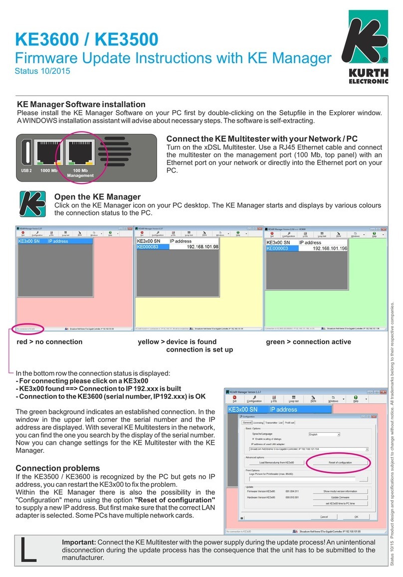
KE-Manager Software
You install the KE Manager software on your PC by double-clicking on the
setup le in the Explorer window. A Windows installation wizard guides you
through the necessary steps.
Connect the Multitester to your network /PC
Switch on the xDSL Multitester. Use an RJ45
Ethernet cable and connect the Multitester
via the management port (top of the device)
to an Ethernet port on your network or direc-
tly to the Ethernet port on your PC.
Starting the KE-Manager
Click on the KE Manager icon on your PC desktop. The KE
Manager loads and shows you the connection status to the PC
using various colours.
The connection status is displayed in the bottom line:
– Please click on a device to connect
– KE3x00 found → Connection to IP 192.xxx is established
– Connection to KE3x00 (serial number, IP 192.xxx) is OK
The green background indicates the established connection. The serial num-
ber and IP address are displayed in the window in the upper left corner. If
there are several KE multitesters in the network, you can nd the one you are
looking for by viewing the serial number. Now you can make settings for the
KE Multitester via the KE Manager.
USB 2
ETH 2
1000 Mb/MGMT
ETH 1
1000 Mb
red > No connection yellow > Device found,
connection is
being established
green > Connection
establisehd

© Kurth Electronic GmbH, All Rights Reserved 15
The KE-Manager is a exible tool for managing the KE3700 / KE3550 and for
downloading measurement data. Like the KE3700 / KE3550, the KE-Manager
is well arranged and largely intuitive to operate.
Conguration
Creation of proles, settings
for basic options such as lan-
guage selection and licensing
as well as uploading channel
lists (IPTV proles) and up-
dating the device rmware.
Detailed update instructions
are stored in the KE Manager
under Help.
Result Centre
Gives precise information
about the active and stored
tests. Available for xDSL,
Ethernet, SHDSL and evalua-
tion of test errors. The display
of the parameters is individu-
ally congurable.
Important: Always connect
the KE Multitester to the
power supply before star-
ting the update process! If
you unintentionally switch
o during the update, you
will have to send in the
device.

© Kurth Electronic GmbH, All Rights Reserved
16
Line measurement
Here you can view the mea-
sured values of the automatic
line analysis (copper test).
ISDN
View of stored ISDN tests.

© Kurth Electronic GmbH, All Rights Reserved 17
Firmware update
You can use the KE Manager to install rmware updates on your KE3700 /
KE3550. We recommend that you keep your device‘s rmware up to date to
take advantage of latest features and optimizations. The currently installed
rmware version can be viewed in the device under Setup > System Infor-
mation.
You can always download the latest rmware from our homepage at
www.kurthelectronic.de/software-downloads/?lang=en.
Click on Conguration in the KE Manager menu bar. A new window opens:
In the conguration menu you can select the desired language and press the
button Update Firmware at the bottom right for the software update.
You can select the KE-Multi-
tester rmware le from your
hard disk or an external drive
via the Explorer of your PC
(the les always have the ex-
tension .upd ). In the selection
window, click Open.
The KE-Manager checks
whether the selected rmwa-
re is more current than the
rmware already installed on
the KE Multitester. You can
then start the upload of the
le to the device. After suc-
cessful transfer, install the
new rmware on the device.
Once you have uploaded the.upd le to the device, the Software Updates
menu item under Setup is activated.
Warning: Do not perform software update with a SFP module plugged in!
Only perform the update with the power supply connected!

© Kurth Electronic GmbH, All Rights Reserved
18
The update process is initiated by selecting this menu item. After this auto-
mated process, the device is restarted. If several modules are to be updated,
you may also need to initate their pending updates.
Activation of software options
You can activate software options for your device via the KE Manager. To do
so, connect the manager to your device and select the Licencing tab in the
Conguration menu item.
A window with available soft-
ware options of your device
and the activation status
opens. To unlock another
software option, double-click
on the desired option and en-
ter the corresponding license
key. After successfully ente-
ring the key, the option is acti-
vated on your device within a
few seconds and is available
after a restart.

© Kurth Electronic GmbH, All Rights Reserved 19
General Data
Graphic TFT Display 3.5“ 240 (RGB) x 320
Languages German, English, French, Spanish,
Italian, Dutch
xDSL Test Port RJ11/ RJ45 (one port)
LAN Port RJ45
GbE Port RJ45
Power supply Built-in LiPo battery
Capacity approx. 5 hours in xDSL test mode
Low batt indication Coloumb counter
Power supply 100 – 230 V AC 50 / 60 Hz, 12 – 18 V / DC
Scope of delivery
Unit comes with:
AC power supply and charger, test leads RJ11-RJ45, RJ11 banana plug
with rubber insulated crocodile clips, Ethernet cable for PC connection,
bag made of rugged cordura with additional space. Windows software for
download of results and upgrade of unit.
Dimensions:
Size 230 x 114/90 x 70 mm
9“ x 4.5/3.5“ x 2.8“
Weight 1,100 / 1,300 g
Housing High impact resistant ABS, with drop protection
Display protection 2 mm Plexiglass
Environmental conditions:
Operation temperature: 0° – +50°C
Storage temperature -20° – +60°C
Humidity: up to 93%, non-condensing

© Kurth Electronic GmbH, All Rights Reserved
20
The device was manufactured according to the following guidelines:
Electromagnetic Compatibility Directive 2014/53/EC
LVD Directive 2014/53/EC
IEC/CISPR: 11:2009 + A1:2010, 16-1-2:2006 Edition 1.2, 16-2-1:2008 +
A1:2010, 16-2-3:2008 + A1:2010
IEC: 61000-4-1:2016, 61000-4-2:2008 Edition 2, 61000-4-3:2006 +
A1:2007 + A2:2010, 61000-4-8:2009, 61326-1:2012, 61326-2-1:2012
Safety instructions
The KE3700 /KE3550 may only be operated with the accessories origi-
nally provided. Using the device with accessories that are not original or
for applications for which it was not intended can lead to incorrect mea-
surements and may damage the device. The relevant safety regulations
in VDE 0100, 0800 and 0805 must be adhered to.
The usage of connections other than those provided can damage
the device. The device should not be used with high-voltage current.
Kurth Electronic assumes no liability for damage resulting from
improper use.
Never apply external voltage to the device.
Open the device only to change the batteries. There are no other
parts in the device that need to be serviced or calibrated.
The measuring device is protected from splashing water and dust by
the front lm covering. However, it is not water proof.
Never pull unnecessarily on the cables connected to the device.
Last revision: 03 / 2021
This manual suits for next models
1
Table of contents
Other Kurth Test Equipment manuals
Popular Test Equipment manuals by other brands

multicomp pro
multicomp pro MP72016 manual

ELBRO
ELBRO TESTER 2550LCD operating instructions

R&S
R&S RTE Series Getting started

BC Biomedical
BC Biomedical ULT-2000 series user manual

MULTI MEASURING INSTRUMENTS CO.,LTD.
MULTI MEASURING INSTRUMENTS CO.,LTD. M-140 instruction manual

Fluke
Fluke 707 Calibration information