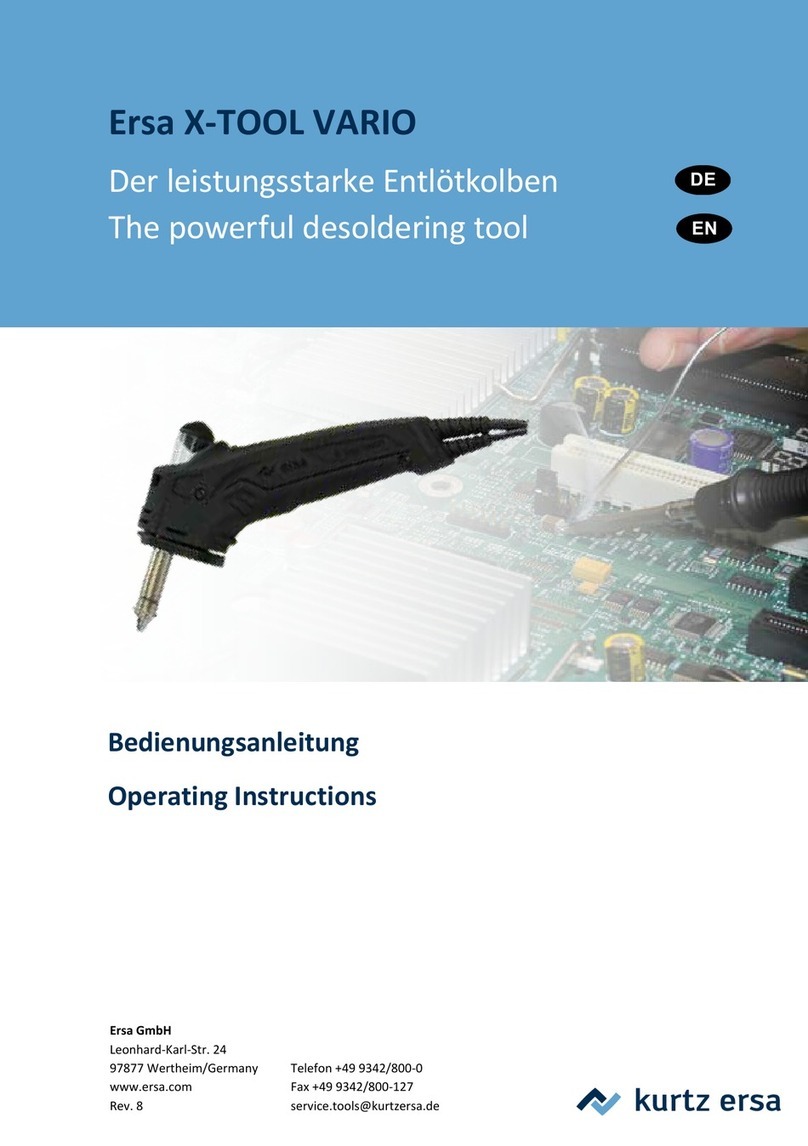
Kurtz Ersa X-Tool CU 100 A User manual

Betriebsanleitung/Operating Instructions
Die leistungsfähige Entlötstation/
The powerful desoldering station
Ersa X-Tool

3BA0062-00 • 2016-05-12 • Rev. 02 2
Inhaltsverzeichnis
1. Einführung ................................. 7
2. Technische Daten ...................... 9
3. Sicherheitshinweise..................11
4. Inbetriebnahme........................ 12
5. Funktionsbeschreibung ........... 15
6. Fehlerdiagnose und
Fehlerbehebung ...................... 17
7. Wartung und
Instandhaltung ......................... 22
8. Ersatzteile und
Bestelldaten............................. 27
9. Garantie................................... 29
1. Introduction................................ 7
2. Technical Data ........................... 9
3. Safety information.....................11
4. Commissioning ........................ 12
5. Functional description.............. 15
6. Error diagnosis and
Remedy ................................... 17
7. Maintenance ........................... 22
8. Spare parts and
ordering information................. 27
9. Warranty .................................. 29
Contents1.

3BA0062-00 • 2016-05-12 • Rev. 02 3
X-Tool Abbildungen
5. Trockenschwamm
6. Ablageständer
7. Netzschalter
8. Vakuumschlauch
9. Vorlter
1. Roundconnector for desold. iron
2. DIG 2000 or MIC 60 iA
control unit
3. Finger button
4. X-Tool desoldering iron
5. Dry sponge
6. Holder
7. Power switch
8. Vacuum hose
9. Prelter
1. Rundstecker d. Entlötkolbens
2. Regeleinheit
DIG 2000 oder MIC 60 iA
3. Fingertaster
4. Entlötkolben X-Tool
X-Tool Pictures
Abb. 1 c/Fig. 1 c Abb. 1 d/Fig. 1 d

3BA0062-00 • 2016-05-12 • Rev. 02 4
X-Tool Abbildungen
1 Backsealing plug
2 Particlelter
3 Residualsolder container
1 Dichtstopfen hinten
2 Partikellter
3 Restlotbehälter
X-Tool Pictures
1
2
3
4
5
4 Lotsammellter
5 Dichtstopfen vorne
4 Soldercollectionlter
5 Front sealing plug
Abb. 2/Fig. 2

3BA0062-00 • 2016-05-12 • Rev. 02 5
X-Tool Abbildungen
Ansicht Z / View Z
blau / blue
weiß-grün / white-green
grün / green (+)
schwarz / black
Thermoelement rot (+)
Red thermocouple
schwarz / black
blau / blue
Ausschnitt X-Tool ohne
Griffschale 2 und ohne
Lotauffangbehälter /
Cut-away of X-Tool with-
out handle shell 2 and
without solder collection
container
Ansicht Y / View Y
Heizkörper/
heating element
X-Tool Pictures
Abb. 3/Fig. 3

3BA0062-00 • 2016-05-12 • Rev. 02 6
1 Locking knob
2 Housing screw
3 Handle half
4 Desoldering head
5 Desoldering tip
1 Ventil
2 Arretierknopf
3 Flachsteckverbindungen
4 Ventilstößel
5 Leiterplättchen
6 Heizelemente
7 Nut
1 Valve
2 Locking knob
3 Tab connectors
4 Valve tappet
5 Chip
6 Heating elements
7 Slot
1 Arretierknopf
2 Gehäuseschraube
3 Griffhälfte
4 Entlötkopf
5 Entlötspitze
12
2
3
2
4 5
1
2 3 4 5 6
653
7
Abb. 4 b/Fig. 4 b
Abb. 4 a/Fig. 4 a
X-Tool Abbildungen X-Tool Pictures

3BA0062-00 • 2016-05-12 • Rev. 02 7
Einführung Introduction
Herzlichen Glückwunsch zum Erwerb dieser
High-Tech Entlötstation von Ersa.
Sie verwenden diese Gerätekombination vor-
zugsweise zum Entlöten bedrahteter Bauele-
mente aus einseitigen, doppelseitigen oder
Multilayer-Leiterplatten.
Hohe Entlötleistung, ergonomische Form und
leichte Bedienbarkeit sind herausragende
Eigenschaften dieses Gerätes.
So sind zum Beispiel die einfach durch Ein-
stecken wechselbaren Entlötspitzen sowie die
leichte Entnahme des Restlots mit Hilfe eines
integrierten Lotbehälters ein Novum in dieser
Geräteklasse.
Ein weiterer Vorteil ist das schlagartig anstehen-
de Vakuum, sobald Sie den Fingertaster betäti-
gen.
Alle Komponenten sind mit antistatischer Ober-
ächeaufgebaut.
Congratulations on purchasing this high-tech
Ersa desoldering station.
We recommend that you use this combination
unit for desoldering wired-up components com-
prising single-sided, double-sided or multiple-lay-
er printed circuit boards.
The outstanding features of this unit are its high
desoldering power, ergonomic shape and ease
of operation.
For example, the exchangeable plug-in deso-
ldering tips and the straightforward extraction of
residual solder by means of an integrated sol-
der container set new standards for this class of
unit.
Another advantage is the fact that the vacuum
is available immediately as soon as you press
thengerbutton.
All components have an anti-static surface.
1.

3BA0062-00 • 2016-05-12 • Rev. 02 8
Einführung Introduction1.
1.1 Lieferumfang
Bitte prüfen Sie den Inhalt der Verpackung auf
Vollständigkeit. Die Verpackungseinheit CU 100
Abesteht aus:
• Compressor Unit CU 100 A
• Netzanschlusskabel
• Vorlter
• Ablageständer mit Viskoseschwamm
• Entlötkolben X-Tool
• Reinigungsnadel
• Ersatz-Restlotbehälter komplett
• Lotsammellter10Stk.
• Partikellter10Stk.
• Reinigungsbürste 3N412
• dieser Betriebsanleitung, Sicherheitshinweise
Die Verpackungseinheit VU 100 A besteht aus:
• Compressor Unit VU 100 A
• Netzanschlusskabel
• Vorlter
• Ablageständer mit Viskoseschwamm
• Entlötkolben X-Tool
• Reinigungsnadel
• Ersatz-Restlotbehälter komplett
• Lotsammellter10Stk.
• Partikellter10Stk.
• Reinigungsbürste 3N412
• dieser Betriebsanleitung, Sicherheitshinweise
Sollten die aufgezählten Komponenten beschä-
digt oder nicht vollständig sein, so setzen Sie
sich bitte mit Ihrem Lieferanten in Verbindung.
1.1 Scope of supply
Please check that the contents of the package
are complete. The CU 100 A packaging unit
comprises:
• Compressor Unit CU 100 A
• Mains lead
• Prelter
• Holder with viscose sponge
• X-Tool desoldering iron
• Cleaning needle
• Spare residual solder container, compl.
• Soldercollectionlter,10pcs.
• Particlelter,10pcs.
• 3N412 cleaning brush
• Operating instructions, safety informations
The VU 100 A packaging unit comprises:
• Compressor Unit VU 100 A
• Mains lead
• Prelter
• Holder with viscose sponge
• X-Tool desoldering iron
• Cleaning needle
• Spare residual solder container, compl.
• Soldercollectionlter,10pcs.
• Particlelter,10pcs.
• 3N412 cleaning brush
• Operating instructions, safety informations
Should the above components be damaged or
incomplete, please contact your supplier.

3BA0062-00 • 2016-05-12 • Rev. 02 9
Technische Daten Technical Data
Kompressorstation CU 100 A
Spannung/Leistung:
230 V~, 50 Hz, 45 W; 115 V~, 60 Hz, 50 W
Beachten Sie bitte die Angaben auf dem
Leistungsschild!
Lautstärke: ca. 55 db (A)
Gewicht: ca. 1,25 kg
Endvakuum: ca. 800 mbar
Durchuss:ca.4,5l/min.
Ausführung: antistatisch
Kompressorstation VU 100 A
Spannung/Leistung:
230 V~, 50-60 Hz, 5 W; 115 V~, 60 Hz, 5 W
Beachten Sie bitte die Angaben auf dem
Leistungsschild.
Druckluft: max. 6 bar, min. 4 bar
Gewicht: 550 g
Endvakuum: max. 900 mbar
Luftverbrauch: 11,5 Normliter bei
100% Einschaltdauer
Ausführung: antistatisch
Compressor Unit CU 100 A
Voltage/Power:
230 V~, 50 Hz, 45 W; 115 V~, 60 Hz, 50 W
Please refer to the information on the
rating plate.
Noise level: approx. 55 db (A)
Weight: approx. 1.25 kg
Ultimate vacuum: approx. 800 mbar
Throughow:approx.4.5l/min.
Design: antistatic
Compressor Unit VU 100 A
Voltage/Power:
230 V~, 50-60 Hz, 5 W; 115 V~, 60 Hz, 5 W
Please refer to the information on the
rating plate.
Compressed air: max. 6 bar, min. 4 bar
Weight: 550 g
Ultimate vaccum: max. 900 mbar
Air consumption: 11.5 standard liters (continu-
ous operation)
Design: antistatic
2.

3BA0062-00 • 2016-05-12 • Rev. 02 10
Technische Daten Technical Data
Entlötgerät X-Tool
Spannung: 24 V~
Anheizleistung: 260 W
Anheizzeit: spitzenabhängig
Gewicht (inkl. Kabel und Spitze): ca. 240 g
Heizelemente: zwei Stück à 60 W (bei 350 °C)
Temperaturmessung: Ni-CrNi-Thermoelement
Startvakuum: bis zu 800 mbar
Weg Griff-Entlötspitze: ca. 70 mm
Ausführung: antistatisch
X-tool desoldering device
Voltage: 24 V~
Heat up rating: 260 W
Heat up time: tip-dependent
Weight (incl. cable and tip): approx. 240 g
Heating elements: 2, 60 W each (at 350 °C)
Temperature measurement:
Ni-CrNi thermocouple
Starting vacuum: up to 800 mbar
Distance from handle to soldering tip:
approx. 70 mm
Design: antistatic
2.

3BA0062-00 • 2016-05-12 • Rev. 02 11
Sicherheitshinweise Safety information
Bitte beachten Sie vor der Inbetriebnahme
unbedingt die beiliegenden Sicherheitshinweise.
Before commissioning, be sure to note the
enclosed safety information.
3.

3BA0062-00 • 2016-05-12 • Rev. 02 12
Inbetriebnahme Commissioning
Compressor Unit CU 100 A
• Set the power switch to 0.
• Firmlyconnecttheprelter(g.1/no.13)onto
the vacuum connection (VAC) of the CU 100A
pump unit.
4.
Abb. 5/Fig. 5
Ablageständer A 44
• Ablageblech von unten einhaken, mit leichter
Drehbewegung so anlegen, dass die Gewin-
debuchsen über den Befestigungsbohrun-
gen liegen, dann die Gewindestifte bündig
einschrauben.
• Viskoseschwamm mit destilliertem Wasser
gut anfeuchten.
Holder A 44
• Hook the holder plate from below and put it
with a slight slowing movement so that the
insert nuts are over the fastening holes, then
screw in the enclosed screws.
• Dampen the viscose sponge well with distilled
water.
Compressor Unit CU 100 A
• Netzschalter auf 0 stellen.
• Vorlter(Abb.1/Pos.13)aufdenVakuuman-
schluss (VAC) der Pumpeneinheit CU 100 A
fest aufstecken.

3BA0062-00 • 2016-05-12 • Rev. 02 13
Inbetriebnahme Commissioning
4.4 Entlötkolben X-Tool
• PrüfenSie,obderLotsammellter(Abb.2/
Pos.4)sowiederPartikellter(Abb.2/Pos.2)
im Restlotbehälter (Abb. 2/Pos. 3) eingebaut
sind.
• Stellen Sie sicher, dass der Restlotbehälter
(Abb. 2/Pos. 3) in den Entlötkolben eingesetzt
ist.
• Prüfen Sie, ob die von Ihnen gewünschte
Entlötspitze (Abb. 4/Pos. 5) in den Wärme-
speicher (Abb. 4/Pos. 4) eingesetzt ist.
• Um Leckagen zu vermeiden, achten Sie
bitte darauf, dass alle Komponenten wie
Entlötspitze, Lotsammelbehälter, Dichtungen,
Vakuumschlauch und Filter fest und luftdicht
miteinander verbunden sind.
• Entlötkolben im Ablageständer (Abb. 6)
ablegen.
• Rundsteckverbinder des Entlötkolbens mit
der Regeleinheit (Abb. 1/Pos. 4) (es kann
eine DIG 2000 oder eine MICRO-CON 60 iA
verwendet werden) verbinden.
• Vakuumschlauch (Abb. 1/Pos. 12) auf den
Vorlter(Abb.1/Pos.13)aufstecken.
Nach Ablauf des Anzeigetests (alle Anzeige-
elemente leuchten für einen kurzen Moment
gleichzeitig auf) wird die Ist-Temperatur der
Lötspitze angezeigt. Sie können nun mit der Löt-
station arbeiten.
4.4 X-Tool desoldering iron
• Checkthatthesoldercollectionlter(g.2/
no.4)andtheparticlelter(g.2/no.2)are
ttedintheresidualsoldercontainer(g.2/
no. 3).
• Make sure that the residual solder container
(g.2/no.3)isinsertedinthedesoldering
iron.
• Checkthatthedesolderingtip(g.4/no.5)
you require is inserted in the heat reservoir
(g.4/no.4).
• To avoid leaks, please make sure that all
components such as the desoldering tip,
solder collection container, seals, vacuum
hoseandltersarermlyconnectedtogether
to give an air-tight connection.
• Place the desoldering iron in the support
stand(g.6).
• Connect the round plug connector of the
desolderingirontothecontrolunit(g.1/
no. 4) (either a DIG 2000 or a MICRO-CON
60 iA can be used).
• Connectthevacuumhose(g.1/no.12)tothe
prelter(g.1/no.13).
After the display test has been run through (all
displayelementsbrieylightupsimultaneously),
the actual temperature of the soldering tip is
displayed. You can now work with the soldering
station.
4.
Abb. 6/Fig. 6

3BA0062-00 • 2016-05-12 • Rev. 02 14
Inbetriebnahme Commissioning
4.5 Einschalten
• Netzstecker (Abb. 1/Pos. 3) in die Compres-
sor Unit CU 100 A bzw. die entsprechende
Regeleinheit einstecken.
• Netzschalter (Abb. 1/Pos. 11) der Vakuum-
und der Regeleinheit einschalten (Glimm-
lampe im Netzschalter leuchtet).
• Gewünschte Arbeitstemperatur an der
Regeleinheit einstellen. Siehe entsprechende
Betriebsanleitung von DIGITAL 2000 A oder
MICRO-CON 60 iA. Die Arbeitstemperatur
sollte in der Regel zwischen 270 °C und
350 °C liegen (siehe Kap. 5.1).
4.5 Switching on
• Pluginthemainsplug(g.1/no.3)inthe
CU 100 A Compressor Unit and into the
corresponding control unit.
• Switchonthepowerswitch(g.1/no.11)
of the vacuum unit and the control unit (glow
lamp in the power switch lights up).
• Set the desired working temperature on the
control unit. See the appropriate operating
instructions (DIG 2000A or MICRO-CON
60 iA). The working temperature should gener-
ally be between 270 °C and 350 °C
(see chap. 5.1).
4.
Wichtig:
Stellen Sie vor jeder Nutzung des Gerätes
sicher, daß alle Original Ersa Filter eingebaut
sind!
Important:
Each time before you use the unit, make sure
thatallgenuineErsaltersareinstalled.

3BA0062-00 • 2016-05-12 • Rev. 02 15
Funktionsbeschreibung
Functional description
5.1 Selecting the correct desoldering
temperature
Always select the lowest possible desoldering
temperature for your job. Excessively high tem-
peratures damage the printed circuit board and
the components.
Guidelines for nominal temperature:
Non-plated printed circuit approx. 270 °C
boards (PCBs) and smaller
components such as resistors,
capacitors and ICs
Single-layer plated PCBs approx.270-300°C
Multiple-layer plated PCBs approx.300-330 °C
Multiple-layer and large comp.approx. 350 °C
5.2 Selecting the correct
desoldering tip
Various desoldering tips with different diameters
and quality levels are available for the desol-
deringiron.TheproleofErsadesolderingtips
matches the meniscus of the soldered joint,
thereby guaranteeing optimum heat transfer.
Select the inside diameter of the desoldering tip
so there is a small ring-shaped gap of approx.
0.1 to 0.2 mm between the connection being
desoldered and the extraction duct. Thus the
used solder can be sucked up.
5.
5.1 Auswahl der richtigen
Entlöttemperatur
Wählen Sie stets die niedrigstmögliche Entlöt-
temperatur für Ihre Aufgabe. Zu hohe Tempera-
turen schädigen die Leiterplatte und die Bauteile.
Richtwerte für Solltemperatur:
Nicht durchkontaktierte Leiter- ca. 270 °C
platten (LP) und kleinere
Bauteile wie Widerstände,
Kondensatoren und ICs
Einlagige durchkontaktierte LP ca. 270-300 °C
Mehrlagige durchkontaktierte LP ca. 300-330 °C
Multilayer und massige Bauteile ca. 350 °C
5.2 Auswahl der richtigen
Entlötspitze
Für den Entlötkolben stehen verschiedene
Entlötspitzen unterschiedlicher Durchmesser
und Qualität zur Verfügung. Die Ersa Entlötspit-
zen sind dem Meniskus der Lötstelle nachgebil-
det, um so eine optimale Wärmeübertragung zu
gewährleisten. Wählen Sie den Innendurchmes-
ser der Entlötspitze so, dass ein kleiner Rings-
palt von ca. 0,1 - 0,2 mm zwischen dem zu entlö-
tenden Anschluss und dem Absaugkanal bleibt,
um das Altlot absaugen zu können.

3BA0062-00 • 2016-05-12 • Rev. 02 16
Funktionsbeschreibung
Functional description
5.
5.3 Wechseln der Entlötspitze
Die Entlötspitze (Abb. 4/Pos. 5) kann mit Hilfe
desamAblageständer bendlichenSpitzenhal-
ters gewechselt werden. Positionieren Sie dazu
die Entlötspitze mit der radial verlaufenden Nut
in eine der Aussparungen des Spitzenhalters.
Fixieren Sie mit einer Hand den Spitzenhalter
und ziehen Sie mit der anderen den Entlötkol-
ben von der Spitze ab. Setzen Sie nun die von
Ihnen gewünschte Entlötspitze in umgekehrter
Reihenfolge in den Wärmespeicher (Abb. 4/Pos.
4) des Entlötkolbens ein.
5.4 Entlöten
Zum Entlöten führen Sie die Spitze des Entlötkol-
bens auf das zu entlötende Objekt, warten kurze
Zeit bis das Lot, welches den Bauelementan-
schlussmitdemAnschlusspadverbindet,vollstän-
dig geschmolzen ist und lösen dann mit Hilfe des
Fingertasters (Abb. 1/ Pos. 6) das bereits an der
Spitze anstehende Vakuum aus.
Dadurch wird das Lot schlagartig durch die
Lötspitze hindurch in den Restlotbehälter beför-
dert.
5.3 Changing the desoldering tip
The desoldering tip (g. 4/no. 5) can be
changed using the tip holder tted onto the
support stand. To do this, position the desolder-
ing tip with its radial slot in one of the holes in the
tip holder. Use one hand to hold the tip holder in
place and use your other hand to pull the deso-
ldering iron off the tip. Now insert the desolder-
ingtipyourequireintotheheatreservoir(g.4/
no. 4) of the desoldering iron by following the
above procedure in reverse order.
5.4 Desoldering
To perform a desoldering operation, guide the tip
of the desoldering iron onto the object in ques-
tionandwaitforashorttimeuntilthesolderx-
ing the component connection to the connection
padhascompletelymelted.Thenpressthen-
ger button (g. 1/no. 6) to release the vacuum
already in the tip.
This causes the solder to be suddenly sucked
through the soldering tip into the residual solder
container.

3BA0062-00 • 2016-05-12 • Rev. 02 17
6. Fehlerdiagnose
und -behebung
Error Diagnosis
and Remedy
6.1 Entlötleistung ungenügend
siehe Kap. 7.1 - „Filter“
6.2.1 Pumpe der CU 100 A läuft
häug an
Vakuumsystem ist undicht. Überprüfen Sie dazu
die Dichtstopfen, Verbindungen und Schläuche.
6.2.2 Pumpe der CU 100 A läuft
nicht an
Ist die Station eingeschaltet und leuchtet die
Glimmlampe im Netzschalter (Abb. 1/Pos. 11)?
Überprüfen Sie Spannungsversorgung und
Sicherung der CU 100 A (siehe Technische
Daten). Sicherung und Ersatzsicherung sind in
der rückseitigen Netzanschlussbuchse unterge-
bracht.
6.3.1 VU 100 A schaltet häug
Undichtigkeit im System. Überprüfen Sie dazu
die Stopfen, Lotkammern, Verbindungen und
Schläuche auf Dichtigkeit.
6.3.2 VU 100 A schaltet überhaupt nicht.
Vakuum steht an.
Eingangsdruck nicht ausreichend.
Überprüfung des Luftdruckes und gegebenen-
falls nachregeln.
6.1 Inadequate desoldering power
see chap. 7.1 - „Filters“
6.2 CU 100 A pump starts up
frequently
The vacuum system is not air-tight. Check the
sealing plugs, connections and hoses.
6.3 CU 100 A pump does not
start up
Is the station switched on and is the glow lamp in
thepowerswitch(g.1/no.11)litup?
Check the electrical power supply and the fuse
of the CU 100 A (see Technical data). The fuse
and a spare fuse are accommodated in the
mains connection socket on the back of the unit.
6.3.1 VU 100 A switches frequently
Leak in the system. Check the sealing plugs, sol-
der containers, connections and hoses.
6.3.2 VU 100 A does not switch at all.
Vacuum exists.
Insufcientpressure.
Check air pressure and readjust it if necessary.

3BA0062-00 • 2016-05-12 • Rev. 02 18
6. Fehlerdiagnose
und -behebung
Error Diagnosis
and Remedy
6.3.3 VU 100 A schaltet überhaupt nicht.
Kein Vakuum vorhanden.
Stromversorgung unterbrochen. Sicherung
unterhalb des Geräteanschlusssteckers auf der
Rückseite des Gerätes prüfen, ggf. auswech-
seln.
6.3.4 VU 100 A schaltet ein und nicht
mehr selbsttätig ab.
Luftausströmgeräusch hörbar, jedoch kein Vaku-
um vorhanden. Setzen Sie sich bitte mit Ihrem
Händler oder direkt mit Ersa (Anschrift siehe
letzte Seite) in Verbindung.
6.4 Entlötspitze wird nicht mehr heiß
Ist die Regeleinheit eingeschaltet und leuch-
tet die Glimmlampe im Netzschalter (Abb. 1/
Pos. 11)?
Prüfen Sie Spannungsversorgung und Siche-
rung der Regeleinheit (siehe Technische Daten).
Sicherung und Ersatzsicherung sind in der rück-
seitigen Netzanschlussbuchse untergebracht.
6.3.3 VU 100 A does not switch at all.
No vacuum.
No power supply. Check fuse below the power
plug at the unit‘s rear side. Replace it if nec-
essary.
6.3.4 VU 100 A switches on but does
not switch off automatically.
Air escapes audibly but no vacuum available.
Please contact your local dealer or Ersa directly
(address see last page).
6.4 Desoldering tip no longer gets hot
Is the control unit switched on and is the glow
lampinthepowerswitch(g.1/no.11)litup?
Check the electrical power supply and the fuse
of the control unit (see Technical data). The
fuse and a spare fuse are accommodated in the
mains connection socket on the back of the unit.

3BA0062-00 • 2016-05-12 • Rev. 02 19
6. Fehlerdiagnose
und -behebung
Error Diagnosis
and Remedy
6.4.1 Prüfung der Heizelemente
Wirddie Entlötspitze nicht heiß, obwohl dieRegel-
einheit offensichtlich funktioniert, so sollten die
beiden Heizelemente (Abb. 5/Pos. 3) überprüft
werden.
Dazu messen Sie am abgezogenen Stecker
(Abb. 1/ Pos. 2) des Entlötkolbens mit einem
Widerstandsmessgerät nach folgendem Sche-
ma:
Die Messwerte gelten nur für kalte (ca. 20 °C)
Heizelemente.
Liegt der Widerstand im Bereich von 2 Ohm,
sind die Heizelemente in Ordnung.
Liegt der Widerstand im Bereich von 4 Ohm, ist
ein Heizelement defekt.
Liegt der Widerstand deutlich über 6 Ohm, sind
beide Heizelemente defekt.
6.4.1 Testing the heating elements
Checkbothheatingelements(g.5/no.3)ifthe
desoldering tip does not get hot despite the fact
that the control unit is obviously functioning. To
do this, use an ohmmeter to conduct a measure-
menton the disconnected connector (g.1/no.
2) of the desoldering iron. Refer to the following
diagram for this measurement:
The measurement values only apply to cold
heating elements (approx. 20 °C).
The heating elements are OK if the resistance is
in the region of 2 ohms.
One heating element is defective if the
resistance is in the region of 4 ohms.
Both heating elements are defective if the
resistanceissignicantlyhigherthan6ohms.
Thermoelement-
fühler / thermo
couple sensor
Heizelement/
heating element
Ist ein Heizelementaustausch notwendig und
wollen Sie ihn selbst vornehmen, gehen Sie wie
unter Kap. 6.4.3 beschrieben vor.
Proceed as described in chap. 6.4.3 if a heating
element has to be replaced and you want to do
the job yourself.
Achtung:
Reparaturen an der Versorgungseinheit dür-
fen nur von autorisiertem Fachpersonal durch-
geführtwerden.ImGerätbendensichspan-
nungsführende Teile. Bei unsachgemäßen
Eingriffen besteht Lebensgefahr!
Important:
Only authorised specialists are allowed to
undertake repairs on the power supply unit. The
unit contains live parts. There is a risk of fatal
injury if inexperienced people work on the unit.

3BA0062-00 • 2016-05-12 • Rev. 02 20
6. Fehlerdiagnose
und -behebung
Error Diagnosis
and Remedy
6.4.2 Prüfung des
Thermoelementfühlers
Wird bei heißer Entlötspitze in der Istwertanzei-
ge der Regelungseinheit nur eine niedrige, z.B.
Raumtemperatur, angezeigt, deutet dies auf ein
defektes Thermoelement hin.
Eine hohe Sollwertanzeige bei nichtbeheizter
Entlötspitze ist Hinweis auf einen Thermoele-
mentbruch.
In beiden Fällen muss der Thermoelementfühler
gewechselt werden.
Da Thermoelementfühler und Heizkörper
zusammen montiert geliefert werden, muss der
komplette Bausatz gewechselt werden. Führen
Sie den Wechsel selbst durch, dann gehen Sie
wie in Kap. 6.4.3 beschrieben vor.
6.4.3 Wechseln von Heizelement und
Thermoelementfühler
• Schalten Sie die Geräte am Netzschalter aus
(Abb.1/Pos.11) und ziehen Sie den 8-poligen
Rundstecker des Entlötkolbens (Abb.1/Pos.2)
ab.
Achtung: Lassen Sie das Gerät einige
Minuten abkühlen.
• Ziehen Sie die Entlötspitze mit Hilfe des Spit-
zenhalteblechs heraus.
• Entnehmen Sie den Restlotbehälter (Abb.1/
Pos. 8) siehe auch Kap. 7.1.1.
• Entspannen Sie das Ventil, indem Sie den
Arretierknopf (Abb. 4/Pos. 1) drücken.
6.4.2 Testing the
thermocouple sensor
An indication of a defect in the thermocouple is
that only a low temperature, e.g. room tempera-
ture, is shown on the actual value display of the
control unit when the desoldering tip is hot.
An indication of a breakage in the thermocouple
is that a high nominal value is displayed although
the desoldering tip is not being heated.
The thermocouple sensor must be replaced in
either case.
The thermocouple sensor and heating ele-
ment are supplied as one subassembly, so it is
necessary to replace them as a complete set.
Proceed as described in chap. 6.4.3 if you are
going to change them yourself.
6.4.3 Changing the heating element
and thermocouple sensor
• Switchofftheunitatthepowerswitch(g.1/
no. 11) and disconnect the 8-pin round
connectorforthedesolderingiron(g.1/no.2).
Important:
Leave the unit for a few minutes
to cool down.
• Pull out the desoldering tip using the tip holder
plate.
• Remove the residual solder container
(g.1/no.8),seealsochap.7.1.1.
• Release the valve by pressing the locking knob
(g.4/no.1).
This manual suits for next models
1
Table of contents
Other Kurtz Ersa Power Tools manuals

Kurtz Ersa
Kurtz Ersa Ersa X-TOOL VARIO User manual

Kurtz Ersa
Kurtz Ersa MULTI-TIP 30 S User manual

Kurtz Ersa
Kurtz Ersa INDEPENDENT 130 User manual

Kurtz Ersa
Kurtz Ersa X-TOOL VARIO User manual

Kurtz Ersa
Kurtz Ersa PTC 70 User manual

Kurtz Ersa
Kurtz Ersa i-CON TRACE User manual

Kurtz Ersa
Kurtz Ersa Ersa PTC 70 User manual