PAGE 5
302825
DPF-MRK-003 REV A 7/23/20
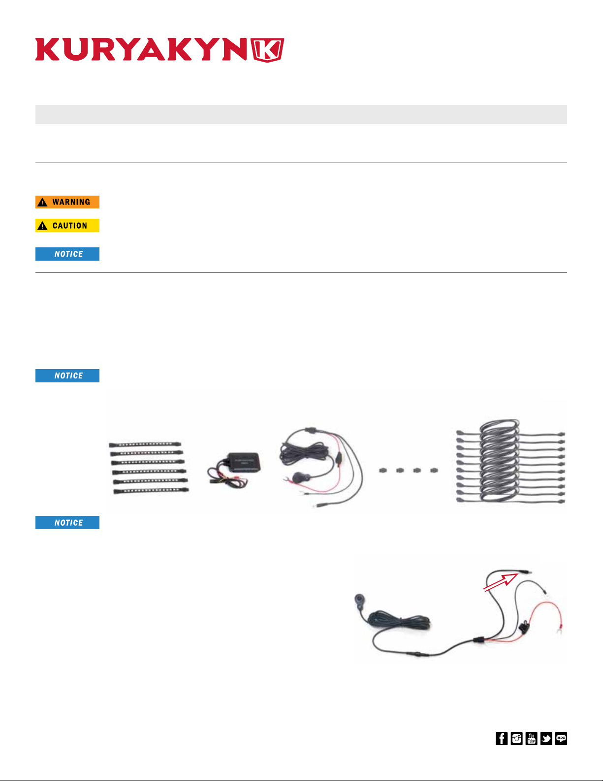
NIGHTCRAWLERS ACCENT LIGHT KIT
866 277 9598 | INFO@KURYAKYN.COM
454 COUNTY ROAD VV SOMERSET, WI 54025
KURYAKYN.COM
INSTALLATION INSTRUCTIONS
-CONTINUED-
STEP 22 Locate provided cable ties and cable tie mounts. Secure all
cords in a safe place. Ensure that cords are secured away
from any moving parts, excessive heat or pinch points.
SECURE ALL WIRING AWAY FROM ANY MOVING PARTS,
PINCH POINTS OR EXTREME HEAT. KURYAKYN WILL NOT
ISSUE A WARRANTY ON ANY ELECTRICAL COMPONENT
THAT FAILS DUE TO PINCHED, CRIMPED, BROKEN,
ABRADED, MELTED OR FRAYED WIRES.
STEP 23 Retest function of lights. Ensure all of the lights properly
function before operating vehicle.
STEP 24 Reinstall any OEM parts that may have been removed
during this installation process.
IT IS THE INSTALLER’S RESPONSIBILITY TO ENSURE THAT
ALL OF THE FASTENERS (INCLUDING PRE-ASSEMBLED)
ARE TIGHTENED BEFORE OPERATION OF THE VEHICLE.
KURYAKYN WILL NOT PROVIDE WARRANTY COVERAGE
ON PRODUCTS OR COMPONENTS LOST DUE TO IMPROPER
INSTALLATION OR LACK OF MAINTENANCE. PERIODIC
INSPECTION AND MAINTENANCE ARE REQUIRED ON ALL
FASTENERS.
LIMITED WARRANTY
Kuryakyn warrants that any Kuryakyn products sold hereunder, shall be free of defects in materials & workmanship for a period of one (1) year from the date
of purchase by the consumer excepting the following provisions:
1. Kuryakyn shall have no obligation in the event the customer is unable to provide a receipt showing the date the customer purchased the product(s).
2. The product must be properly installed, maintained & operated under normal conditions.
3. Kuryakyn shall not be liable for any consequential & incidental damages, including labor & paint, resulting from failure of a Kuryakyn product, failure to
deliver, delay in delivery, delivery in nonconforming condition, or for any breach of contract or duty between Kuryakyn & a customer.
4. Kuryakyn products are often intended for use in specic applications. Kuryakyn makes no warranty if a Kuryakyn product is used in applications other
than intended.
5. Kuryakyn electrical products are warranted for one (1) year from the date of purchase by the consumer. L.E.D.’s contained in components of Kuryakyn
products will be warranted for defects in materials & workmanship for 3 years from the date of purchase whereas all other components shall be warranted
for one (1) year.
6. All warranty claims must be directed to the place of purchase. Merchandise sold through internet auction sites or any other unauthorized reseller shall
not carry a Kuryakyn warranty. If unsure, please contact the place of purchase to verify they are an authorized Kuryakyn reseller.
RETURN POLICY
Merchandise determined to be defective may be returned up to one year from the date of purchase. Returns must be processed through original seller.
Returned merchandise for any other reason other than warranty claims must be in like new condition & subject to a 20% restocking fee. All returns are
subject to inspection for determination of full or partial credit. Any returned part that shows evidence of being used or installed contrary to manufacturer’s
instructions, &/or subjected to improper handling, packaging or return shipping by the customer, will not be eligible for exchange, refund or warranty
consideration. All returned electrical items will be inspected & tested. If electrical item is deemed functional, no credit will be issued & item will be returned.
All sales are nal on discontinued or closeout merchandise.
©2015 KURYAKYN HOLDINGS, LLC ALL RIGHTS RESERVED
KURYAKYN, KURYAKYN K logo and the marks appearing on this instruction sheet are registered and common law trademarks of Kuryakyn Holdings except noted third-party trademarks. A full listing of
trademarks and trademark registrations owned by Kuryakyn Holdings can be found at www.kuryakyn.com/legal-notice.
Emissions Notice: The California Air Resources Board (CARB) does not permit the use of aftermarket emission-related parts(s) that alter the performance of OEM emission-related devices unless CARB has
issued an Executive Order, other than on racing vehicles on closed courses. Check your local laws and manufacturer’s information.
Listed Manufacturers and product model names are for reference only. All product and company names are trademarks or registered trademarks of their respective holders. Use of them does not imply any
aliation with or endorsement by them. All specications are subject to change without notice.
For additional information on third-party product and company names, please consult our Web page at www.kuryakyn.com/legal-notice
2825