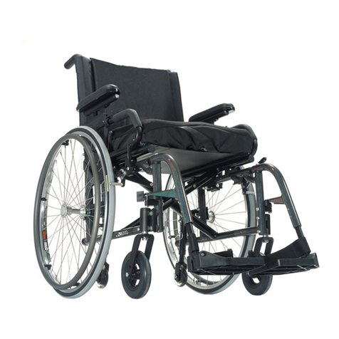
Kuschall Advance User manual

Service Manual
KÜSCHALL ADVANCE

2
KÜSCHALL ADVANCE
© Küschall AG, Switzerland | 2014-07
Service Manual
TABLE OF CONTENTS
GENERAL...................................................................................................................... 4
Introduction 4
Spare parts and adaptations 4
Tightening Allen screws 4
Torque 5
Checks 5
Identifying and alleviating malfunctions 5
OVERVIEW ....................................................................................................................6
Seat width (SB) 6
Seat depth (ST) 6
Front seat height (SHv) 6
Rear seat height (SHh) 6
Seat angle (SW) 6
Backrest height (RH) 7
Backrest angle (RW) 7
Lower leg length (UL) 7
FRAME........................................................................................................................... 8
Mounting frames and seat plates 8
Attaching the quick release frame to the seat plate 10
BACKREST...................................................................................................................11
Adjusting the backrest height 12
Setting the backrest angle 12
Adjusting the backrest joint 13
Replacing the backrest tube 13
Replacing the handle 14
Replacing foldable push handles 14
FOOTRESTS ................................................................................................................15
Install / replace footrest and adjust height 15
Assembling the foot plate cover 16
Replacing the footplate support 16
Fitting and adjusting high-mounted footrest 17
Attaching the forward footrest 17
Angle-adjustable footplate, adjusting the angle 17
Fitting the fold-up footrest 18
SIDE PARTS .................................................................................................................19
Armrest / Siderest 19
Clothes-guard / mudguard 20
FRONT WHEELS........................................................................................................ 22
Replacing a front wheel 22
Replacing a front wheel fork 22
Setting the steering error angle 23
Checking and adjusting the alignment of the supporters 23
Shift supporter on the frame 23
REAR WHEELS ........................................................................................................... 25
Attach vertical brace to the seat plate 25
Changing the wheel chamber / Fitting and adjusting an axle 25
Ensuring the rear wheels are parallel 29
Adjusting the removable axle 29

3
KÜSCHALL ADVANCE
© Küschall AG, Switzerland | 2014-07
Service Manual
BRAKES ....................................................................................................................... 30
Positioning the parking brake 30
Fitting / adjusting the parking brake 30
OPTIONS & ACCESSORIES.......................................................................................31
Antitipper 31
Active antitipper 32
Transit wheels 32
Fitting the pelvic belt 33

4
KÜSCHALL ADVANCE
© Küschall AG, Switzerland | 2014-07
Service Manual
GENERAL
Introduction
This service manual is part of the instructions and contains the tech-
nical information for servicing, configuring and repairing a küschall®
wheelchair.
WARNING!
Danger of accident and severe injuries.
If the wheelchair is improperly set it can cause
accidents and severe injuries.
▸Changes to the wheelchair may only be carried out
by the provider.
To guarantee the required safety and reliability, all wheelchairs must
be comprehensively checked once a year.
In part, assembly and adjustment require extensive experience.
For this reason, the following assembly instructions have been split
into three categories:
Requirement Symbol
Easy – technical understanding required
Intermediate – specialist knowledge required
Dicult – specialist wheelchair assembly knowledge
and experience required
The required tools and their respective sizes are listed above each
instruction. The instructions include information on the torques with
which the respective screw connections must be tightened. Adhering
to the given torques requires the use of a torque spanner.
Tools Symbol
Allen key Ã3, 4, 5
Hexalobular key (Torx®) T15
Phillips screwdriver Ò2
Straddle spanner 10, 11, 19
Socket spanner/ring spanner 8, 10
Spare parts and adaptations
All spare parts can be purchased from küschall®Customer Services.
An electronic spare parts catalog is available by logging onto
www.kuschall.com. Only original spare parts may be used. Installing
additional adaptations to a küschall®wheelchair requires the prior
written approval of Küschall AG.
Tightening Allen screws
Allen keys are not designed for greater forces. When tightening or
loosening an Allen screw, it is therefore advisable to apply force to
the nut to prevent the hexagon socket from being damaged.
Tightening and loosening
Turn the nut with a socket spanner (only use a straddle spanner
if there is insucient space) and merely hold the screw tight with
the Allen key.

5
KÜSCHALL ADVANCE
© Küschall AG, Switzerland | 2014-07
Service Manual
Tightening and loosening if there is no nut
If an Allen screw is directly screwed into a screw thread, the screw must be tightened
using an Allen key.
iEnsure that the Allen key is of good quality
and not worn.
Torque
All screw connections must be tightened with the torques specified in the following
instructions.
Checks
Visual check
Check all components for cracks, especially the areas around joints and welded seams.
Checking the screw connections
Check all bolts with the torques specified in the instructions regularly, and adjust if
required.
CAUTION!
Several screw connections have been secured with thread locking adhesive. If these are
opened, they must be secured again using new thread locking adhesive.
High-strength and low-strength adhesives are available. For torque entries notice shall be
made whether an adhesive and which adhesive needs to be used.
Identifying and alleviating malfunctions
Malfunction Possible cause Measure
The wheelchair will not
move in a straight line
Frames are not parallel Make the frames parallel
Frames and/or supporters are not vertical to the
ground Make the frames vertical
Alignment of the supporters is incorrect Correct the alignment of the supporters
Incorrect tire pressure in a rear wheel Correct tire pressure
One or more spokes broken Replace defective spoke(s)
Spoke unevenly tensioned Tighten excessively loose spokes
Dirty or damaged wheel bearings Clean or replace bearings
Footplate is not set to the same height on the left
and right, or the screws have come loose
Set the fooplate in the footplate guides
to the same height on both sides and
tighten the bolts.
The wheelchair tips
backwards too easily
Rear wheels have been fitted too far forward Fit rear wheels further back
Backrest angle too great Reduce backrest angle
Seat angle too great Use longer vertical struts
The brakes engage poorly
or asymmetrically
Incorrect tire pressure in one or both rear wheels Correct tire pressure
Brake setting incorrect Correct brake setting
Roll resistance is too great Insucient tire pressure in the rear wheels Correct tire pressure
Rear wheels are not parallel Ensure that the rear wheels are parallel
The front wheels wobble
when moving fast
Insucient tension in the front wheel bearings block Lightly tighten the nut in the bearings
block axle
Front wheel is worn flat Replace front wheel
The front wheel is sti or
stuck Dirty or damaged bearings Clean or replace the bearings
Increased forward tip
tendency Frame deformed Replace frame
6
KÜSCHALL ADVANCE
© Küschall AG, Switzerland | 2014-07
Service Manual
OVERVIEW
OVERVIEW
Seat width (SB)
Available seat widths: SB 340 to 460 in 20 mm steps.
Changing the seat width is very complicated. The seat module, the
backrest, the real wheel axles and the footrest have to be replaced.
Seat depth (ST)
Available seat depths: ST 360 to 520 in 20 mm steps.
To alter the seat depth, the complete seat plate as well as the seat
cushion may need to be replaced.
Front seat height (SHv)
The front seat height is dependent on several factors that interact
with each other - Frames, forks and front wheel sizes.
Chap. Front wheels, Shift supporter on the frame,
Chap. Front wheels, Replacing a front wheel,
Chap. Front wheels, Replacing a front wheel fork,
Chap. Frame, Mounting frame and seat plate.
Rear seat height (SHh)
The desired seat height is achieved through the proper position on
the rear wheel fastener on the vertical brace. The vertical brace is
available in two sizes (short and long) covering seat heights from 370
to 490 mm.
The wheel position and the rear seat height are infinitely adjustable.
Chap. Rear wheels, Set axle position at the vertical brace.
Chap. Rear wheels,Tipping point adjustment.
Seat angle (SW)
The seat angle is determined by the dierence between the rear seat
height (SHh) and the front seat height (SHv).

7
KÜSCHALL ADVANCE
© Küschall AG, Switzerland | 2014-07
Service Manual
OVERVIEW
75˚ short
75˚ medium
75˚ long
90˚ long
90˚ medium
90˚ short
3"4" 5" 6"
A
BC
DE
F
short long
Backrest height (RH)
The height of the backrest can be adjusted by moving the backrest tube.
Chap. Backrest, Adjusting the backrest height.
Backrest angle (RW)
The angle of the backrest can be changed by repositioning the excentre plate in the backrest joint plate.
Chap. Backrest, Adjusting the backrest angle.
Lower leg length (UL)
To change the lower leg length, the footrest can be fixed at a higher or lower position.
Chap. Frame, Mounting frame and seat plate.
Chap. Footrests, Install / replace footrest and adjust height.
The shortest lower leg lengths can be achieved using the high-mounted footrest.
Chap. Footrests, Fitting and adjusting high-mounted footrest.

8
KÜSCHALL ADVANCE
© Küschall AG, Switzerland | 2014-07
Service Manual
FRAME
The küschall®Advance®frames are made from aluminium with frame angles
of 75° and 90° In addition there are aluminium frames with adduction.
All frames are available in short, medium and long variants.
Frame Frame angle 75° Frame angle 90°
Front wheel 3“ 4“ 5“ 6“ 3“ 4“ 5“
SHv 450 short short short short short short short
SHv 460 short short short short short short short
SHv 470 medium short short short short short short
SHv 480 medium medium short short medium short short
SHv 490 medium medium medium short medium medium short
SHv 500 medium medium medium medium medium medium medium
SHv 510 long medium medium medium medium medium medium
SHv 520 long long medium medium long medium medium
SHv 530 long long long medium long long medium
SHv 540 long long long long long long long
SHv 550 long long long long long long long
Exceptions:
If the frame is 75° and UL > 430: Use medium frames instead of the shorter ones.
If the frame is 75° and UL > 480: Use long frames instead of the medium ones.
If the frame is 90° and UL > 420: Use medium frames instead of the shorter ones.
If the frame is 90° and UL > 470: Use long frames instead of the medium ones.
For lower leg lengths, the high-mounted footrest must be used,
Chap. Footrests, Fitting and adjusting high-mounted footrest.
Mounting frames and seat plates
Diculty: Tools: Ã510
The frame tube can be mounted on three dierent positions on the seat
plate.
Push the frame tube Ⓑinto the desired position on the seat plate Ⓒyx.
Tighten the Ⓐbolts.
Perform the same setting on both sides.
iMake sure that there is not conflict between the frame and brakes
or between the front and rear wheels.
FRAME
Ⓐà7 Nm

9
KÜSCHALL ADVANCE
© Küschall AG, Switzerland | 2014-07
Service Manual
FRAME
Checking that the frames are parallel and adjusting
Diculty: Tools: Ã5 10
The frames must run parallel to one another when the foot bar is
mounted (Ⓐ = Ⓑ). If this is not the case, the mounted foot bar is
either too narrow or too wide or the frame tubes are misshapen.
Fitting the appropriate foot bar, Chap. Footrests, Fitting/replacing
footrest and adjusting height.
or
Replacing misshapen frame(s), Chap. Frame, Fitting the frames to
the seat plate.
If a carbon footplate is fitted, the interval Ⓑcan be set.
Checking that the frames are vertical and adjusting
Diculty: Tools: Spirit level, Ã5 10
The frames and/or supporters must be vertical to the ground,
otherwise the wheelchair will not move in a straight line.
Ensuring that the alignment of the supporters is correctly
adjusted, Chap. Castors, Checking and adjusting the alignment of
the supporters.
Place both sides of the spirit level on the surface Ⓐof the
supporter and check that it is vertical.
If the supporters are not vertical, loosen the screw connections
between the seat plate and the frame on both sides.
Align the frames with the mounted footrest vertically.
Retighten the bolts on both sides, Chap. Frame, Fitting the
frames to the seat plate.
A
B
A

10
KÜSCHALL ADVANCE
© Küschall AG, Switzerland | 2014-07
Service Manual
FRAME
Attaching the quick release frame to the seat
plate
Diculty: Tools: T15, Ã5,10
Fit the countersunk bolt Cin the sixth hole of the seat plate Awith
washer Dand nut E.
Insert spring B.
Spray the sleeve F with PTFE-Spray.
Insert sleeve Fsuch that the slot is parallel to the boreholes in the
seat plate.
Introduce the female coupling Ginto the seat platesuch that the
sleeve Fis inserted inside the coupling.
WARNING!
Danger of accidents and severe injuries as a result of the
loosening of the front frame from the seat plate.
▸Ensure that the bolts Hare correctly fitted
(tightening torque, bolt locking).
Fit both bolts Hwith washers Iand nuts Jin the second and third
holes.
3Spray the lever axle K and the plastic sliding disk with PTFE-Spray.
Push the distance sleeve Lover the lever axle K.
Guide the lever axle through the borehole Minto the coupling.
WARNING!
The clamping force of the quick release lever can be re-
duced by the unintentional loosening of the nut, meaning
that the lever can no longer be closed.
▸Ensure that the nut Non the lever axle is correctly tighte-
ned.
▸Ensure that the headless bolt Ois secured with the cor-
rect torque.
Fit the nut Nonto the lever axle.
Counter the headless bolt Oin the nut against the lever axle.
4Attach the warning notice sticker Pto the cleaned and grease-free
underside of the seat plate in accordance with the position
specifications (mm) in the graphic.
A B
C
D E
J
H
G
F
I
K
L
M
N
O
60,0
30,0
P
Eà4 Nm (high-strength)
Jà5 Nm (high-strength)
Oà4 Nm (low-strength)
3
4

11
KÜSCHALL ADVANCE
© Küschall AG, Switzerland | 2014-07
Service Manual
BACKREST
BACKREST
The adjustable back is fitted with velcro®bands and a cover. Apart
from the adjustable back there is the light cover, which is produced
individually for each backrest height (RH) and seat width (SB).
A 1-band strap Ⓖis placed beneath the stabilizing bar if there is a
clothes-guard, and a 2-bands strap Ⓗif there is a mudguard.
E
F
A
B
C
D
H
H
G
G
I
Backrest height (RH) to pushhandles, telescopic tubes and bands
RH
Without pushhandles ⒸHeight adjustable pushhandles,
rearset Ⓒ
Bands above
stabilizing bar
Top
band
Telescopic
tube bended
Ⓒ
Bands above
stabilizing bar
Top
band
270 1-band Ⓖ
endband,
5 cm Ⓕ
- - -
285 1-band ⒼXS 1-band Ⓖ
endband,
5 cm Ⓕ
300 1-band ⒼXS 1-band Ⓖ
315 1-band ⒼXS 1-band Ⓖ
330 1-band Ⓖ
endband, 10 cm Ⓕ
XS 1-band Ⓖ
345 1-band ⒼXS 1-band Ⓖ
10
cm
Ⓕ
360 1-band ⒼXS 1-band Ⓖ
375 1-band ⒼS 2 x 1-band Ⓖ
5 cm
Ⓕ
390 2 x 1-band ⒼS 2 x 1-band Ⓖ
405 2 x 1-band ⒼS 2 x 1-band Ⓖ
endband, 10 cm Ⓕ
420 2 x 1-band ⒼS 2 x 1-band Ⓖ
435 2-bands+1-band M 2 x 1-band Ⓖ
450 2-bands+1-band M 2-bands+1-band
465 2-bands+1-band M 2-bands+1-band
480 2-bands+1-band M 2-bands+1-band
Backrest height (RH) to cover, backrest tube, pushhandles and bands
RH Cover
Back-
rest-
tube Ⓘ
Standard pushhandles Ⓐ
Foldable pushhandles Ⓑ
Push-
handle Ⓐ
Telescopic
tube
straight Ⓑ
Bands above
stabilizing bar
Top
band
270* S - 1-band Ⓖ
backrest-
band Ⓔ
5 cm
285 S S S XS 1-band Ⓖ
300 S S S XS 1-band Ⓖ
315 S L S XS 1-band Ⓖ
backrestband, 10 cm, 2-part Ⓔ
330 S L S XS 1-band Ⓖ
345 M L S XS 1-band Ⓖ
360 M L S XS 1-band Ⓖ
375 M L S XS 2 x 1-band Ⓖ
390 M L L S 2 x 1-band Ⓖ
405 M L L S 2 x 1-band Ⓖ
420 L L L S 2-bands+1-band
435 L L L S 2-bands+1-band
450 L L L S 2-bands+1-band
465 L L L S 2-bands+1-band
480 L L L S 2 x 2-band Ⓗ
* RH 270 only for standard pushhandles

12
KÜSCHALL ADVANCE
© Küschall AG, Switzerland | 2014-07
Service Manual
BACKREST
Adjusting the backrest height
Readjusting the push handle/telescopic tube
Diculty: Tools: Ã38
Remove the backrest padding.
Remove the screw connection Ⓐand adjust the desired height of
the push handle or the telescopic tube. Insert the screw
connection Ⓐagain and tighten the nut.
Carry out the same setting on both sides.
Refit the backrest padding.
iIf the desired height cannot be achieved, you must use a dierent
telescopic tube or push handle.
Setting the backrest angle
The following angles (measured from the seat) can be set:
Diculty: Tools: Ã310
Fold down the backrest and release the counter nut Ⓓof the
adjustment screw Ⓐand screw it in completely.
Remove the screw Ⓑon the excentre plate Ⓒ. Remove the
excentre plate Ⓒand reinsert it in the desired position.
The excentre plates must be set identically on both sides of the
wheelchair.
Reinsert the screw Ⓑand tighten it.
Adjust the backrest joint, Chap. Backrest, Adjusting the backrest
joint.
A
Ⓐà7 Nm
90°
94°
82°
86°
86°
78°
78° 82° 86° 90° 94°
90°
94°
82°
86°
86°
78°
90°
94°
82°
86°
86°
78°
90°
94°
82°
86°
86°
78°
90°
94°
82°
86°
86°
78°
A
D
B
C
A
Ⓑà4 Nm

13
KÜSCHALL ADVANCE
© Küschall AG, Switzerland | 2014-07
Service Manual
BACKREST
Adjusting the backrest joint
Diculty: Tools: 10
Put the backrest up and let the pin Ⓐengage.
Press the backrest forwards to ensure the joint cannot move.
Unscrew the screw Ⓒuntil it touches the spigot Ⓔof the seat
frame.
Screw the screw back in by between a ¼ and a ½ turn and
counter with the counter nut Ⓓ..
Correctly adjust the backrest joint on both sides.
Function check:
Sit in the wheelchair and lean back so that the backrest is strained.
Upon pulling the release cord Ⓑ, the pin Ⓐmust be easily removed
on both sides and must fully glide back in upon letting go of the
release cord.
The excentre plates must be set identically on both sides of the
wheelchair, Chap. Backrest, Adjusting the backrest angle.
Check:
Check the settings of the adjustment screws Ⓒon both sides.
The screw head must only lightly touch the adjustment screw Ⓔ on
the
seat plate Ⓕwhen the backrest is in the upright position.
If necessary, readjust the length by releasing the counter nut and
tightening or loosening the adjustment screw. Then retighten the
counter nut Ⓓ.
Incorrectly adjusted adjustment screws result in damage to the
backrest joint’s mechanism.
Replacing the backrest tube
Diculty: Tools: Ã3, 4 8, 10
Remove the backrest padding.
Slide the backrest bands upwards or downwards to gain access to
the screws Ⓐ. Remove the screws and nuts on both sides.
Remove the push handles or the telescopic tubes and remove the
upper Velcro®bands.
Remove the screws Ⓑon the backrest joint.
Remove the lower Velcro®bands and the sleeve Ⓓwith the
adjustment screw from the backrest tube Ⓒand fit both to the
new backrest tube.
Fit the backrest tube to the backrest joint with the screws Ⓑ.
Here, first fit the lower screw followed by the upper screw.
Fit the upper Velcro®bands and the push handles or the
telescopic tubes again and fix them with screws Ⓐand nuts.
Carry out the same setting on both sides.
Refit the backrest padding.
E
C
A
B
D
C
Ⓓà7 Nm
Ⓔà4 Nm
A
B
D
C
Ⓐà7 Nm
Ⓑà7 Nm

14
KÜSCHALL ADVANCE
© Küschall AG, Switzerland | 2014-07
Service Manual
BACKREST
Replacing the handle
An adhesive (e.g. hair spray) is used in these instructions. When
applied to the handle, this substance works as a lubricant and as an
adhesive once dry.
After drying, the adhesive used must be able to resist a pull-o
force of 750 N. If in doubt, contact Küschall AG.
Diculty:
Remove the old handle.
Remove any residue (residual adhesive, grease, dust) from the
push handle tube.
Apply a thin layer of hair spray all over the surface of the push
handle tube onto which the handle is to be slid.
Apply a thin layer of hair spray to the inside of the handle.
Slide the new handle onto the push handle tube.
Move the handle into the correct position (grooves facing
upwards).
i
If a long handle has been fitted and this is to be replaced with a
short one, the push handle tube must be shortened by 35 mm.
The push handle tube must be replaced when switching from a
short to a long handle.
Replacing foldable push handles
Diculty: Tools: Hole punch pliers 6mm, Ã3, 4
Remove the old foldable push handle.
Pull down the backrest cover G on the telescopic tube, until its
hole B is uncovered.
!IMPORTANT!
Make sure that the threaded insert F(part no. 1580450) supplied
with the new push handle is used for assembly.
Place the threaded insert Fin the telescopic tube.
Punch a hole through the backrest cover with a distance of
10 mm from the upper egde, using hole punch pliers (see graphic
below).
Slide the new foldable push handle Aonto the telescopic tube.
Fix the foldable push handle with screw C(M5x12).
Pull up the backrest cover, until it covers completely the rear hole
in the pushhandle.
Fix the foldable push handle with screw D(M5x14) and washer H.
Check screws Eon both sides of the push handle and re-tighten
if necessary.
Carry out the same steps for the other push handle.
!IMPORTANT!
Make sure that the folding force is approximately 5 N (0.5 kg).
i
The retrofit of foldable push handles requires new tubing.
Cà3 Nm (low-strength)
Dà7 Nm (low-strength)
10 mm

15
KÜSCHALL ADVANCE
© Küschall AG, Switzerland | 2014-07
Service Manual
FOOTRESTS
FOOTRESTS
The footrest must be selected in accordance with the seat width.
A standard footrest and an angle-adjustable footrest are available.
Furthermore, there is a choice between a high-mounted footrest and
a fold-up footrest.
Possible lower-leg length in relation to the frame and footrest
Frame Footrests Mögliche UL hochmontiert
[mm]
Mögliche UL im
Rahmen montiert
[mm]
75° / 90°
short
Footrest
220 - 340 350 - 420*
medium 220 - 390 400 - 470*
long 220 - 440 450 - 510*
75° / 90°
short
Angle-adjustable
footplate
220 - 340 350 - 420*
medium 220 - 390 400 - 470*
long 220 - 440 450 - 510*
75° / 90°
short
Fold-up footplate
220 - 300 310 - 420*
medium 220 - 350 360 - 470*
long 220 - 400 410 - 510*
For the 75° frames 10 mm more is possible.
Install / replace footrest and adjust height
Diculty: Tools: Ã3
Undo bolt Ⓒby approx. five turns.
Tap on the bolt Ⓒ to release the wedge inside.
Remove the footrest Ⓐfrom the frame and replace it with a new
one.
Slide the footrest Ⓐ into the footrest guidance Ⓑto the desired
height.
Tighten bolt Ⓒagain.
Carry out the same setting on both sides.
iIf the desired lower leg length cannot be achieved, a high-
mounted footrest must be used, Chap. Footrests, Fitting and
adjusting a high-mounted footrest. It is possible to install a longer
or shorter frame.
Ⓒà4 Nm

16
KÜSCHALL ADVANCE
© Küschall AG, Switzerland | 2014-07
Service Manual
FOOTRESTS
Assembling the foot plate cover
Diculty: Tools: Ã3, drill, drill bit: ∅7mm
Position and ax the footplate support Ⓒcleanly to the footplate
Ⓑ.
Thread the footplate through the holes on the footplate support.
Removing the foot plate support
Drill through foot plate (7 mm).
Blind rivets (Tubtara) should be used in accordance with supplier
instructions.
Fasten the footplate support Ⓐwith screws.
Replacing the footplate support
Diculty: Tools: Ã3
Remove screws Ⓐand footplate support Ⓒ.
Fasten the new foot plate support Ⓐwith bolts.
Ⓐà4 Nm

17
KÜSCHALL ADVANCE
© Küschall AG, Switzerland | 2014-07
Service Manual
FOOTRESTS
Fitting and adjusting high-mounted footrest
Diculty: Tools: Ã3, 5 10
Attach frame bar Ⓓfor the high mounted foot rest on both sides
using the wedge connections Ⓐon the front frame.
Fix the clamp set Ⓒto both sides of the frame using the screw
connection Ⓑ. Only tighten lightly.
3Slide the high-mounted footplate Ⓔinto the clamp set and to the
desired height.
Tighten the screw connections Ⓑon both sides.
Attaching the forward footrest
Usually the foot rest is attached backward.
Diculty: Tools: Ã3
Remove complete footrest, Chap. Footrests, Install / replace
footrest, adjust height.
Rotate footrest 180° so that the long side of the footplate is facing
forward.
3Re attach the complete footrest, Chap. Footrests, Install / replace
footrest, adjust height.
Set the desired footplate angle, Chap. Footrests, Angle-adjustable
footplate, adjusting the angle.
Angle-adjustable footplate, adjusting the
angle
Diculty: Tools: Ã4 10
To adjust the angle, release the four screw connections Ⓐuntil
the footplate can be moved.
The angle of the footplate must be set so that the user’s feet
cannot slide o the plate.
Check and/or adjust the distance between the left and the right
sides by pushing in or pulling out the tubes below the footplate in
such a way that the bearings blocks are perpendicular to the
ground.
Tilt the footplate into the desired position and tighten the screw
connections Ⓐ.
A
D
B
C
E
A
Ⓐà4 Nm
Ⓑà7 Nm
A
Ⓐà13 Nm

18
KÜSCHALL ADVANCE
© Küschall AG, Switzerland | 2014-07
Service Manual
FOOTRESTS
Fitting the fold-up footrest
Diculty: Tools: Ã3,4,5 10
Fix the reinforcing bar Ⓐto the frame.
Then, firmly tighten the screw connection Ⓑ.
On both sides, slide the telescopic tubes Ⓓinto the frame.
On both sides, fix the telescopic tubes at the desired height using
the wedge connection Ⓒ.
Carry out the same setting on both sides.
3Insert the sleeve Ⓔinto the mounting part Ⓕof the right
telescopic tube. Fix it using the screw Ⓖ.
4Place the left tube of the footplate Ⓗinto the mounting part on
both sides of the left telescopic tube, each with a washer. Fix it
using the screw Ⓘ.
Insert the right tube of the footplate into the mounting part of the
right telescopic tube. Adjust the distance between the left and
the right sides by pushing in or pulling out the tubes below the
footplate in such a way that the bearings blocks are perpendicular
to the ground.
Tilt the footplate into the desired position and tighten the
footplate screws, Chap. Footrests, Angle-adjustable footplate,
adjusting the angle.
iThe footrest can also be fitted the other way around (right footrest
tube fixed, left tube moving).
Ⓑà7 Nm (low-strength)
Ⓒà4 Nm
Ⓖà7 Nm (low-strength)
Ⓘà7 Nm (low-strength)

19
KÜSCHALL ADVANCE
© Küschall AG, Switzerland | 2014-07
Service Manual
SIDES
SIDE PARTS
Armrest / Siderest
The clothes-guard fitted as standard can be augmented with an
armrest.
The armrest may be equipped with both a clothes guard and mudgu-
ard.
Fitting an armrest
Diculty: Tools: Ã3, 5 10
Fold the backrest forwards.
Turn wire ring Ⓘand remove the plunger pin Ⓗand spring Ⓙ.
Remove screw Ⓕand screw connections Ⓖ.
Remove the backrest spigots Ⓑand replace them with the arm
rests Ⓐon both sides.
Fit the connecting tube with screws Ⓒon both sides.
Attach screw connection Ⓖand bolts Ⓕ.
Attach plunging pin with spring and wire ring.
Setting the armrest height
Diculty: Tools: Ã48
3To adjust the height as required, position the sleeve Ⓓin the tube
so that the screw connection Ⓔcan be fixed to the appropriate
hole in the tube. Place the armrest in the holder.
Set the desired armrest height on both sides.
Fitting and adjusting a height-adjustable siderest
Diculty: Tools: Ã4, 5 Ò2 10
Attach the holder Ⓑand the clamps Ⓒusing the bolts Ⓐon both
sides of the seat plate.
Durch Anziehen bzw. Lösen der Schrauben Ⓓkann eingestellt
werden, wie leicht sich die Seitenlehne herausziehen bzw.
einstecken lässt.
Height-adjustable armrest; set height
Diculty: Tools: Ã4
Insert the siderest Ⓔinto the holder Ⓑ.
Loosen Ⓕfor the height adjustment and slide the armrest into the
desired position.
Retighten the screws Ⓕat the height-fixation.
D
E
C
A
B
I
J
H
G
F
A
D
E
F
B
C
A
D
Ⓕà4 Nm
Ⓔà7 Nm
Ⓐà7 Nm

20
KÜSCHALL ADVANCE
© Küschall AG, Switzerland | 2014-07
Service Manual
SIDES
Clothes-guard / mudguard
The clothes-guard fitted as standard can be replaced by a mudguard.
Clothes-guard and mudguard are made of carbon.
Possible sizes clothes-guard:
Clothes guard size relative to rear seat height, wheel size and wheel position
Wheel size 22‘‘ 24‘‘ 25‘‘ 26‘‘
Wheel position
[mm] 140 125 110 95 80 140 125 110 95 80 140 125 110 95 80 140 125 110 95 80
SHh
370 LLLLM---------------
380 LLLMM---------------
390 L L M M M L L L L L - - - - - - - - - -
400 LMMMMLLLLLLLLLL- - - - -
410 MMMMMLLLLMLLLLLLLLLL
420 MMMMMLLLMMLLLLLLLLLL
430 M M M M M L L M M M L L L L M L L L L L
440 MMMMML MMMML L L MML L L L L
450 MMMMMMMMMML L MMML L L L M
460 MMMMMMMMMML MMMML L L MM
470 MMMMMMMMMMMMMMML L MMM
480 MMMMMMMMMMMMMMML MMMM
490 - - - - - MMMMMMMMMMMMMMM
Possible sizes mudguard:
Mudguard size relative to rear seat height, wheel size and wheel position
Wheel size 22‘‘ 24‘‘ 25‘‘ 26‘‘
Wheel position
[mm] 140 125 110 95 80 140 125 110 95 80 140 125 110 95 80 140 125 110 95 80
SHh
370 LLLLM---------------
380 LLLMM---------------
390 L L M M M L L L L L - - - - - - - - - -
400 L M M M M L L L L L XL L L L L - - - - -
410 M M M M M L L L L M L L L L L XL XL L L L
420 MMMMMLLLMMLLLLLXLLLLL
430 M M M M M L L M M M L L L L M L L L L L
440 MMMMML MMMML L L MML L L L L
450 MMMMMMMMMML L MMML L L L M
460 MMMMMMMMMML MMMML L L MM
470 MMMMMMMMMMMMMMML L MMM
480 MMMMMMMMMMMMMMML MMMM
490 - - - - - MMMMMMMMMMMMMMM
L
M
L XL
Other manuals for Advance
3
Table of contents
Other Kuschall Wheelchair manuals

Kuschall
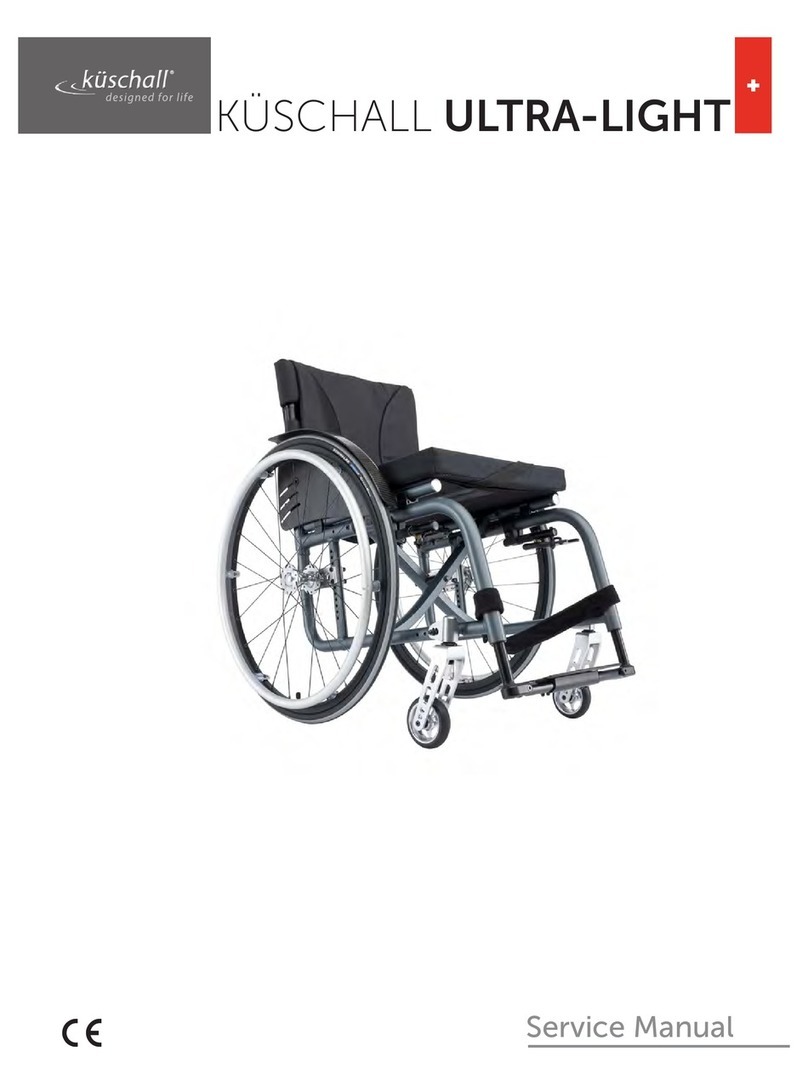
Kuschall Ultra-Light User manual

Kuschall
Kuschall CHAMPION User manual

Kuschall
Kuschall Wheelchair User manual

Kuschall
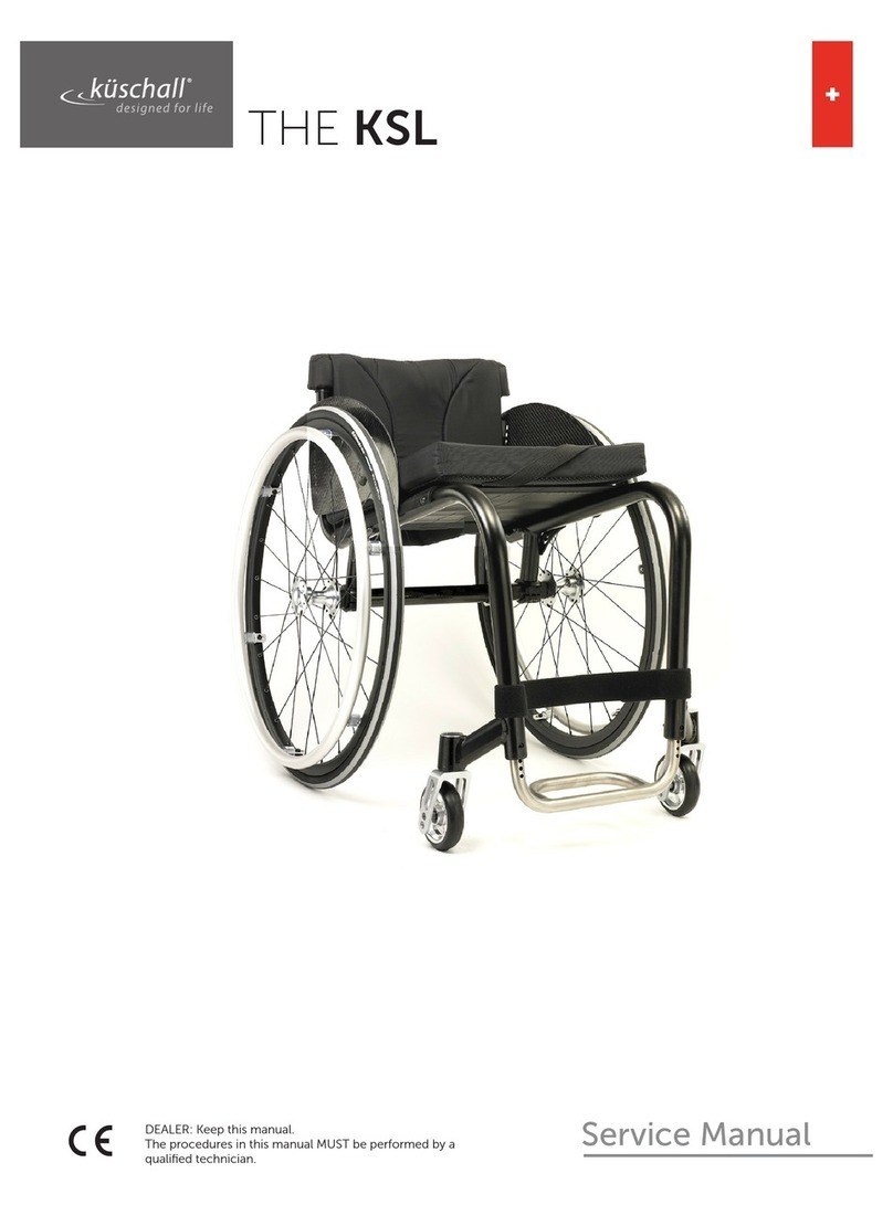
Kuschall KSL User manual

Kuschall
Kuschall K-SERIES User manual

Kuschall
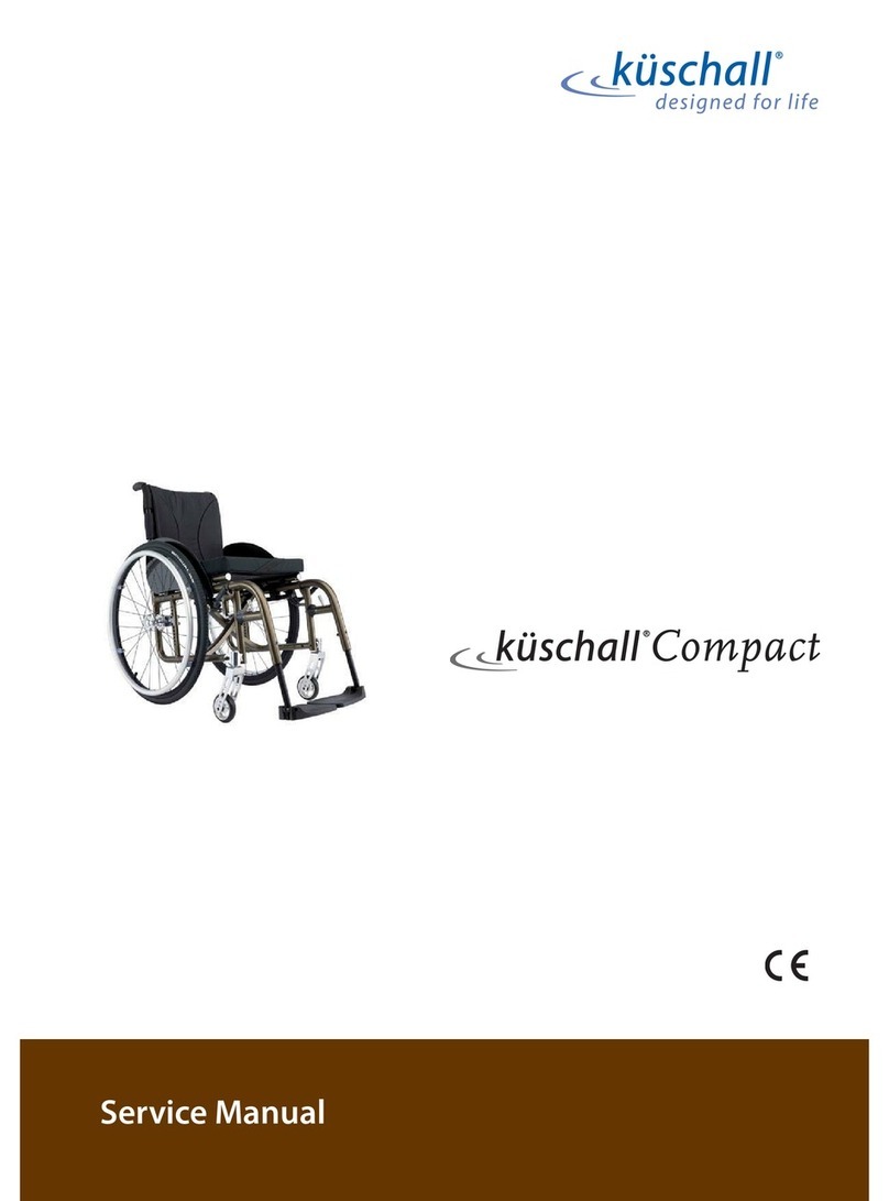
Kuschall Compact User manual

Kuschall
Kuschall KSL User manual

Kuschall
Kuschall K-SERIES User manual

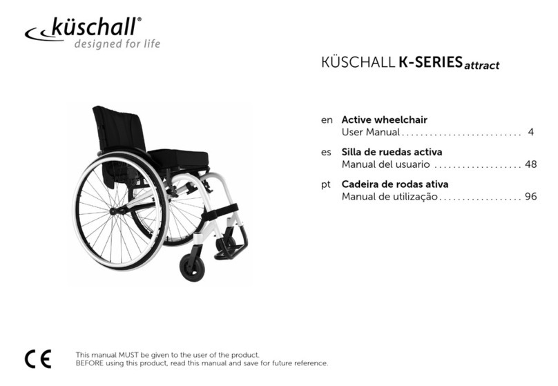
Kuschall
Kuschall K-SERIES ATTRACT User manual
Popular Wheelchair manuals by other brands

DeVilbiss Healthcare
DeVilbiss Healthcare drive D-LITE Instructions for use

Blandino
Blandino SPRING Use and maintenance handbook

Invacare
Invacare TDX SC parts list

Maximex
Maximex Secura Premium 23556 Assembly instructions

ROHO
ROHO AGILITY Operation manual

Sanction Industry
Sanction Industry MF-5630 instruction manual