Kuschall KSL User manual

Service Manual
THE KSL
DEALER: Keep this manual.
The procedures in this manual MUST be performed by a
qualified technician.


3© Küschall AG, Switzerland | 2015-05
Service Manual
TABLE OF CONTENTS
GENERAL...................................................................................................................... 4
Introduction 4
Spare parts 4
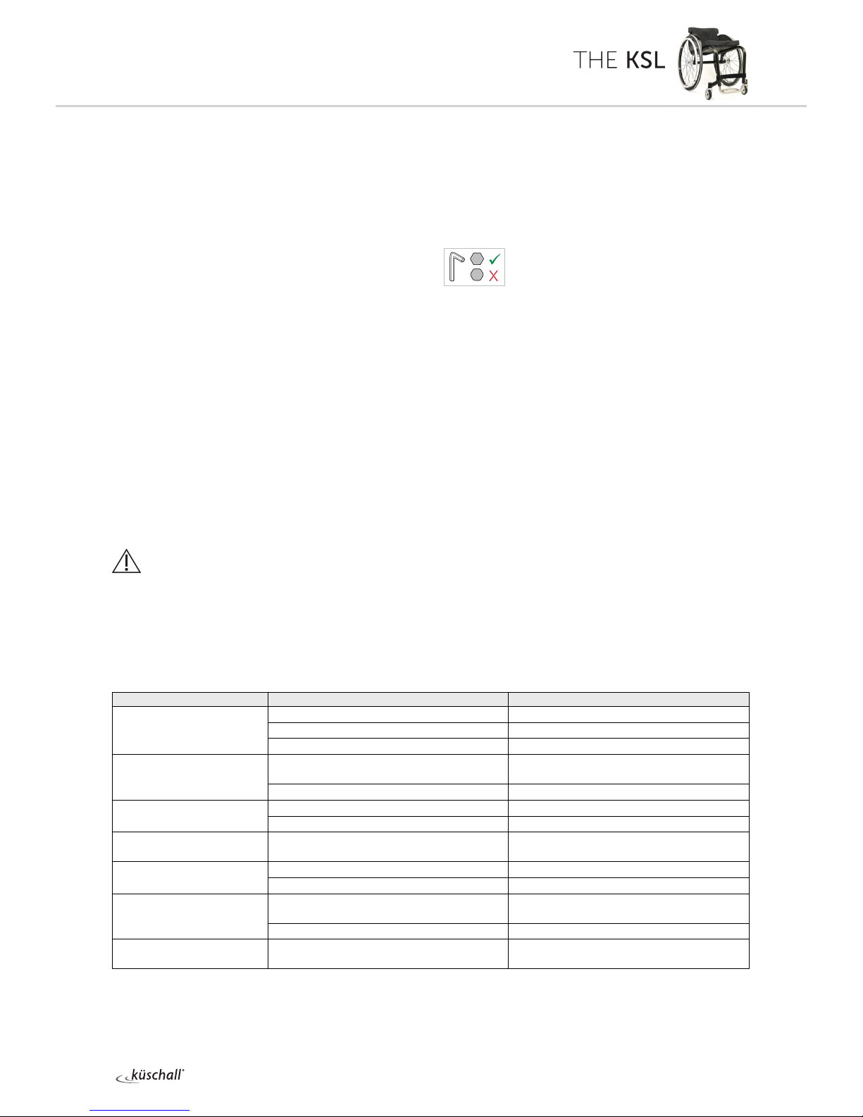
Fastening with hexagon socket bolts 4
Torque 5
Checks 5
Identifying and repairing faults 5
FRAME............................................................................................................................6
Adjusting the frame 6
Changing the frame 6
SEAT ...............................................................................................................................7
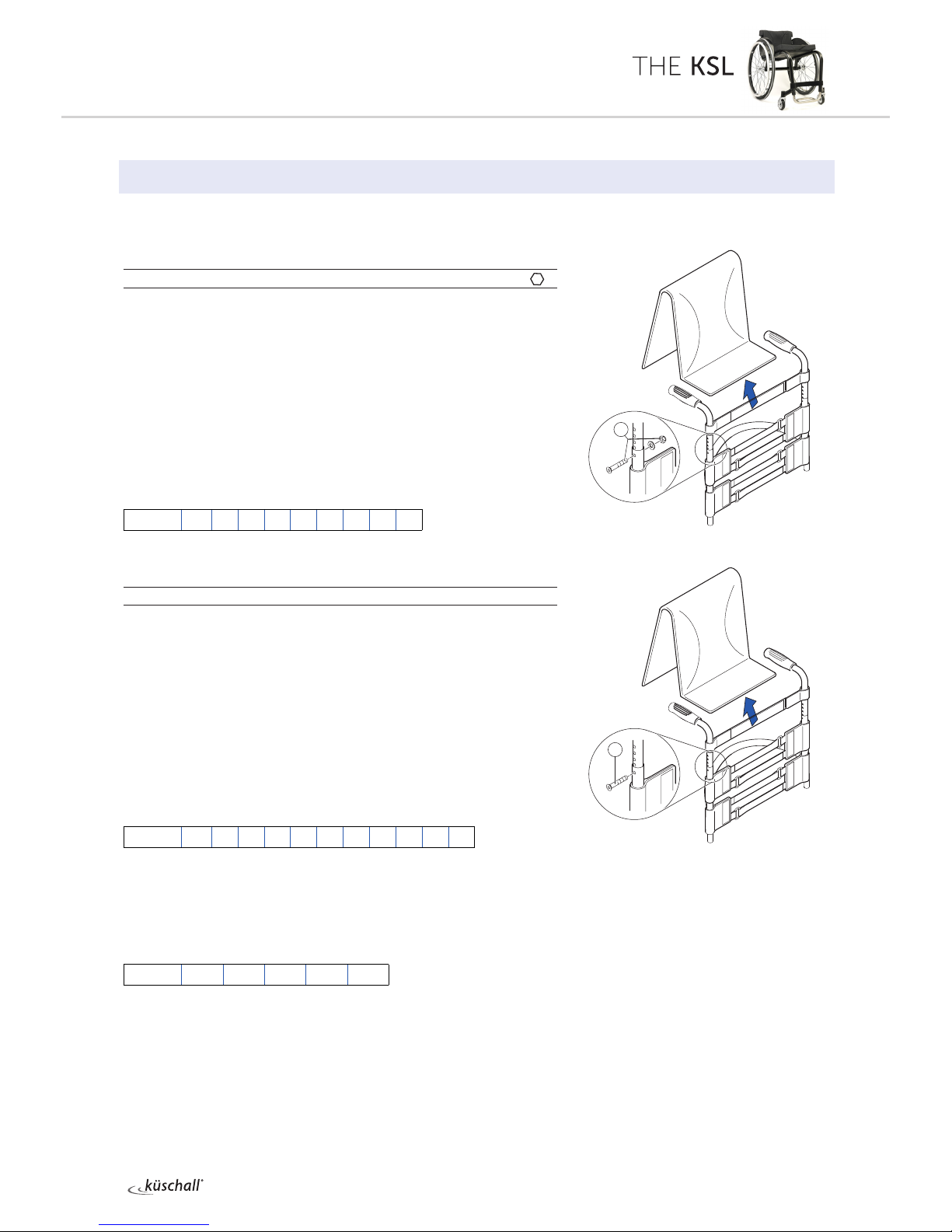
Adjusting the seat height 7
Replacing the seat cover 7
BACKREST.................................................................................................................... 8
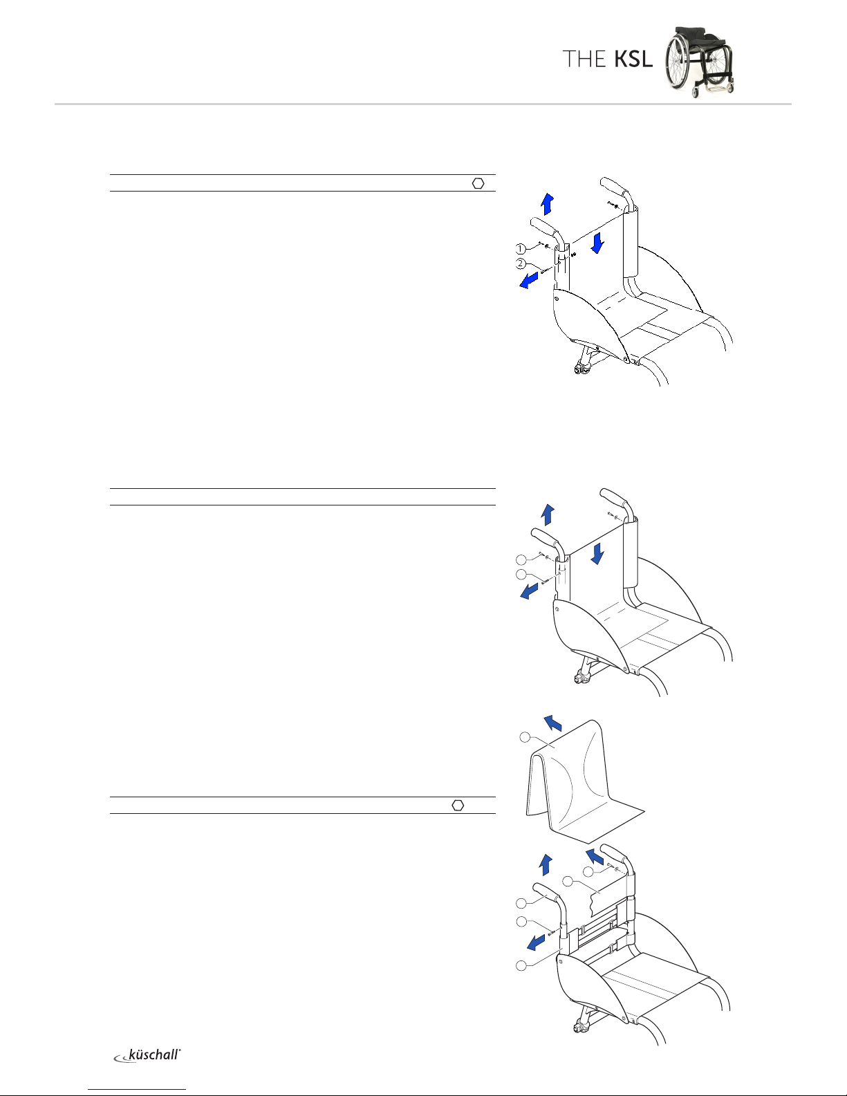
Adjusting the backrest height 8
Backrest angle 8
Tipping point of the wheelchair 8
Replacing the Standard Light backrest cover 9
Replacing Velcro®tapes for adjustable backrests 9
Replacing push handles with Light cover 10
From serial number 13G08000785: Replacing push handles with Light cover10
Replacing push handles with adjustable backrest 10
Replacing foldable push handles 11
Foldable backrest, angle adjustable (optional) 12
FOOTRESTS ................................................................................................................13
Replacing the footrest 13
Adjusting the height of the footrest 13
Adjusting the angle of the footrest 13
SIDES............................................................................................................................14
Fitting the clothes guard 14
Fitting the mudguard 14
FRONT WHEELS.........................................................................................................15
Replacing the front wheel fork 15
Replacing the front wheel 15
Cleaning the front wheel bearings 15
REAR WHEELS ............................................................................................................16
Checking the tyre pressure 16
Checking the spoke tension 16
Checking that removable axles are seated correctly 16
Adjusting the removable axles 16
Replacing the rear wheels 17
Replacing the axle 17
Ensuring the rear wheels are parallel 17
Repairing or changing an inner tube 17
Fitting tubed tyres to carbon wheels 18
BRAKES ........................................................................................................................19
Fitting / adjusting the parking brake 19
OPTIONS & ACCESSORIES...................................................................................... 20
Fitting an antitipper 20

4© Küschall AG, Switzerland | 2015-05
Service Manual
GENERAL
Introduction
This service manual is part of the instructions and contains the
technical information for servicing, configuring and repairing a
küschall®wheelchair.
WARNING!
Danger of accident and severe injuries.
If the wheelchair is improperly set it can cause acci-
dents and severe injuries.
▸Changes to the wheelchair may only be carried out
by the provider.
To maintain the necessary levels of safety and reliability, every
wheelchair must be thoroughly examined once a year.
Some aspects of the assembly and configuration of the wheelchair
require a high level of expertise. These assembly instructions therefo-
re break the various tasks down into 3 categories:
Requirement Symbol
Easy – technical understanding required
Medium – technical knowledge required
Dicult – technical knowledge and expertise in
assembling wheelchairs required
The required tools and their respective sizes are listed above each
instruction. The instructions include information on the torques
with which the respective screw connections must be tightened. Ad-
hering to the given torques requires the use of a torque spanner.
Tools Symbol
Allen key Ã3, 4, 5
Phillips screwdriver Ò2
Straddle spanner 10, 11, 19
Socket spanner/ring spanner 8, 10
Spare parts
All spare parts can be purchased from küschall®'s Customer Services.
An electronic spare parts catalog is available by logging onto
www.kuschall.com. Only original spare parts may be used.
Installing additional adaptations to a küschall®wheelchair requires the
prior written approval of Küschall AG.
Fastening with hexagon socket bolts
Hexagon socket bolts are not designed to withstand an excessive
application of force. When tightening or undoing a hexagon socket
bolt, force must be applied to the nut wherever possible to avoid
damaging the bolt.

5© Küschall AG, Switzerland | 2015-05
Service Manual
Tightening and undoing
Turn the nut using an open-end spanner, or preferably a socket spanner, using the Allen
key simply to stop the bolt turning.
Tightening and undoing when no nut is present
If an Allen screw is directly screwed into a screw thread, the screw must be tightened
using an Allen key.
iEnsure that the Allen key is of good quality
and not worn.
Torque
All screw connections must be tightened with the torques specified in the following
instructions.
Checks
Visual check
Prüfen Sie alle Komponenten auf Risse, insbesondere die Bereiche um Verbindungen
und Schweißnähte herum.
Checking the screw connections
Check all bolts with the torques specified in the instructions regularly, and adjust if
required.
CAUTION!
Mehrere Schraubverbindungen wurden mit Schraubensicherungslack gesichert.
Sollten diese Schraubverbindungen geönet werden, müssen sie wieder mit neuem
Schraubensicherungslack gesichert werden.
Zur Verfügung stehen hochfeste und niederfeste Sicherungsmassen in flüssiger Form.
Bei den Drehmomentangaben wird ggf. darauf hingewiesen, ob ein Sicherungskleber zu
verwenden ist, bzw. welcher zu verwenden ist.
Identifying and repairing faults
Fault Possible cause Action
The wheelchair does not
travel in a straight line
Incorrect tyre pressure on one rear wheel Correct tyre pressure
One or more spokes broken Replace broken spoke(s)
Spokes tightened unevenly Tighten loose spokes
The wheelchair tips too
easily
Frame geometry does not meet
specifications Fitting an antitipper
Backrest angle too great Replace backrest with smaller backrest angle
Removable axles cannot be
inserted correctly
Removable axles dirty Clean removable axles
Removable axles misaligned Adjust removable axles
The brakes are gripping
poorly or asymmetrically
Incorrect tyre pressure in one or both rear
tyres Correct tyre pressure
The rolling resistance is very
high
Tyre pressure in rear tyres is too low Correct tyre pressure
Rear wheels not parallel Ensure rear wheels are parallel
The front wheels wobble
when moving fast
Too little tension in front wheel bearing block Tighten the nut on the bearing block axle
slightly
Front wheel has worn smooth Change front wheel
The front wheel is sti or
stuck
Bearings are dirty or faulty Clean or replace the bearings

6© Küschall AG, Switzerland | 2015-05
Service Manual
FRAME
FRAME
Adjusting the frame
The seat width, seat depth, lower leg length and tipping point are
determined by the design of the frame and cannot be changed retro-
spectively.
A modification of the tip behaviour can only be achieved by ordering
a new, one-o backrest. The seat depth can be adjusted by changing
the hole position.
Changing the frame
Please contact the küschall®Customer Service department if you
wish to change the frame.

7© Küschall AG, Switzerland | 2015-05
Service Manual
SEAT
SEAT
Adjusting the seat height
The seat height can only be adjusted by fitting a larger or smaller rear
wheel and at the same time using a larger or smaller front wheel fork.
Possible front seat heights: SHv [mm] 450 - 510 (530*)
* From serial number 13G08000785
As the seat angle is dictated by the design of the frame, the seat
height rear (SHh) also changes by 10 mm.
The following settings are possible:
iTo ensure that the frame is straight and the axles of the front
wheel forks are perpendicular to the ground, choose one of the
combinations listed in the table.
Replacing the seat cover
Diculty: Tools: Ã3, 4, 5 8, 10
Remove mudguard or clothes guard by loosening
bolts .
Remove bolts on both sides of the seat cover.
Remove seat cover and replace with new one.
iOwing to the tension inherent in the design of the frame, it may
not be possible to fit the seat cover. In this case the axle holders
must be undone.
Undo axle holders
Fit new seat cover using bolts .
Ensure the rear wheels are parallel, Chap. Rear Wheels, Ensuring
the rear wheels are parallel, and tighten axle holder bolts.
Fit mudguard or clothes guard using bolts .à7 Nm
à4 Nm
Front seat height (SHv) according to front wheel and rear wheel
SHv [mm] possible
SHh [mm]
Rear
wheel Frame Front wheel
3'' 4'' 5''
450 - 500 (520*) 400 - 480 24‘‘ 75° D C B
90° B A --
460 - 510 (530*) 400 - 480 25‘‘ 75° E D C
90° C B --
* From serial number 13G08000785
25''
24''
3'' 4'' 5''
A B C D E
75°90°
1
2
3
1

8© Küschall AG, Switzerland | 2015-05
Service Manual
BACKREST
BACKREST
Adjusting the backrest height
Readjusting the push handle/telescopic tube
Diculty: Tools: Ã3 8
Remove the backrest padding.
Remove the screw connection and adjust the desired height of
the push handle or the telescopic tube.
Insert the screw connection again and tighten the nut.
Carry out the same setting on both sides.
Refit the backrest padding.
iIf the desired height cannot be achieved, you must use a dierent
telescopic tube or push handle. If the backrest height is too high,
the backrest tube can be cut o and redrilled.
Possible backrest heights:
RH [mm] 270 285 300 315 330 345 360 375 390
From serial number 13G08000785:
Readjusting the push handle/telescopic tube
Diculty: Tools: Ã3
Remove the backrest padding.
Remove the bolt and adjust the desired height of the push
handle or the telescopic tube by bringing the threaded insert to
the appropriate position.
Insert and tighten the bolt again
Carry out the same setting on both sides.
Refit the backrest padding.
iIf the desired height cannot be achieved, you must use a dierent
telescopic tube or push handle.
Possible backrest heights:
RH [mm] 270 285 300 315 330 345 360 375 390 405 420
Backrest angle
If you want to change the backrest angle, then the complete back-
rest will have to be replaced.
Possible backrest angles:
RW 74° 78° 82° 86° 90°
iChanging the backrest angle also modifies the tipping point of the
wheelchair.
Tipping point of the wheelchair
The tipping point of the wheelchair can only be modified by fitting a
new backrest with a larger or smaller backrest angle. The seat depth
can also be adjusted by changing the hole position.
1
à7 Nm
1
à7 Nm

9© Küschall AG, Switzerland | 2015-05
Service Manual
BACKREST
Replacing the Standard Light backrest cover
Diculty: Tools: Ã3 8 Ò2
Remove push handles, if fitted, Chap. Back, Replacing push
handles.
Remove bolts and, clothes guard or mudguard.
Open the Velcro®fasteneron both sides.
Pull the backrest cover up and o and slip the new backrest
cover over the backrest tubes.
Close the Velcro®fasteners again on both sides.
Fit mudguard or clothes guard.
Fit push handles, if required.
Replacing Velcro®tapes for adjustable
backrests
Diculty: Tools: Ã3, 4, 5 8, 10 Ò2
The upper backrest bands can be taken straight o, the backrest
must be removed in order to access the lower ones.
Remove backrest cover.
1Remove mudguard or clothes guard.
Push the backrest band down in order to access the bolts .
Remove nuts and bolts on both sides
(From serial number 13G08000785: Remove bolts on both sides).
Pull the push handle and end bandout of the backrest tube
(if fitted).
Pull the upper backrest band o the backrest tube .
Remove bolts on both sides.
Remove the seat cover, the bolts on both sides and the back-
rest.
Replace the lower backrest band and put the backrest to one
side.
iOwing to the tension inherent in the design of the frame, it may
be extremely dicult to reposition the backrest in the frame. In
this case the axle holders must also be undone.
Undo axle holders
Insert the new backrest and secure using bolts .
Fit the seat cover, insert and tighten bolts .
Ensure the rear wheels are parallel, Chap. Rear wheels, Ensuring
the rear wheels are parallel, and tighten axle holder bolts.
Pull the upper backrest band over the backrest tube .
Refit the push handles and end band and secure using bolts
and nuts on both sides (From serial number 13G08000785:
secure using bolts on both sides).
Fit mudguard or clothes guard.
à7 Nm
à7 Nm
à7 Nm
à4 Nm
à7 Nm
4
1
7
2
3
6
5
2
3
1

10 © Küschall AG, Switzerland | 2015-05
Service Manual
BACKREST
Replacing push handles with Light cover
Diculty: Tools: Ã3, 4 Ò2 8
Remove screwon both sides.
Push the cover down a little to expose the bolt connections .
Remove bolt connections on both sides.
If necessary, remove mudguard or clothes guard.
Pull out push handle and replace with new one.
Insert and tighten bolt connections on both sides.
Fit cover to both push handles using screw.
iIf a push handle is not going to be fitted, telescopic tubes with a
new Light cover that is sealed at the top can be used.
From serial number 13G08000785:
Replacing push handles with Light cover
Diculty: Tools: Ã3, 4 Ò2
Remove screwon both sides.
Push the cover down a little to expose the bolt .
Remove bolts from the backrest tube on both sides.
If necessary, remove mudguard or clothes guard.
Pull out push handle and replace with new one.
Insert bolt through the backrest tubes and the new push
handles and tighten bolts on both sides.
Fit cover to both push handles using screws.
iIf a push handle is not going to be fitted, telescopic tubes with a
new Light cover that is sealed at the top can be used.
Replacing push handles with adjustable
backrest
Diculty: Tools: Ã3, 4 8 Ò2
Remove backrest cover .
Remove bolts and end band.
Push the backrest band down a little to expose the bolt .
Remove bolt on both sides.
Pull the push handlesfrom the backrest tubes.
Slip the end bandover the new push handles.
Fit the push handles in the desired position using the bolts . Se-
cure the end bandto the push handles again using the
bolts .
à4 Nm
à7 Nm
à4 Nm
à7 Nm
à4 Nm
à7 Nm
1
2
6
2
5
4
3
1

11 © Küschall AG, Switzerland | 2015-05
Service Manual
BACKREST
Replacing foldable push handles
Diculty: Tools: Hole punch pliers 6 mm, Ã3, 4
Remove the old foldable push handle.
Pull down the backrest cover F on the telescopic tube, until its
hole B is uncovered.
IMPORTANT!
Make sure that the threaded insert E(part no. 1580450) supplied
with the new push handle is used for assembly.
Place the threaded insert Ein the telescopic tube.
Punch a hole through the backrest cover with a distance of
10 mm from the upper egde, using hole punch pliers (see
graphic below).
Slide the new foldable push handle Aonto the telescopic tube.
Pull up the backrest cover, until it covers completely the rear
hole in the pushhandle.
Fix the foldable push handle with screw C(M5x14) and washer
G.
Check screws Don both sides of the push handle and re-tighten
if necessary.
Carry out the same steps for the other push handle.
IMPORTANT!
Make sure that the folding force is approximately 5 N (0.5 kg).
IMPORTANT!
Fixing screw C (M5x14) may only be used once. Alternatively the
screw can be cleaned (remove old thread locking adhesive) and
reinstalled with new low-strength thread locking adhesive.
i
The retrofit of foldable push handles requires new tubing.
Cà7 Nm (low-strength)
10 mm

12 © Küschall AG, Switzerland | 2015-05
Service Manual
BACKREST
Foldable backrest, angle adjustable (optional)
Optionally, a foldable, angle-adjustable backrest can be fitted.
For assembling a special küschall®training is necessary.
iWhen switching to the foldable backrest, the axle of the rear
wheels must also be replaced with a new one that is 2 cm wider,
Chap. Rear wheels, Replacing the axle.
Pre-assembling the foldable backrest
Diculty: Tools: Ã3, 4, 5 8, 10
Push the back band onto the back tubes.
Fit the end plugs into the backrest tubes on both sides.
Mount the backrest joint plates on both backrest tubes.
Fit the backrest angle adjustor through the back band on
both backrest tubes facing forwards or backwards, Chap. Back,
Backrest angle.
Fitting a foldable, angle-adjustable backrest
Diculty: Tools: Ã3, 4, 5 8, 10
drill, drill bit: ø6.1
Remove mudguard or clothes guard from both sides.
Remove the seat cover.
Remove old backrest.
1Drill a new hole in the frame, on both sides, with ø 6.1 mm bit,
at a distance of 203 mm from the rearmost hole .
Re-fit the seat cover.
Push the seat tube into the frame on both sides and secure
with
bolt .
Fit end plugs into end of both seat tubes .
Push the pre-assembled backrest onto seat tubes and secure
on both sides with bolt .
Secure support plate using bolt through the seat cover.
Secure support plate using bolt (spacer, plastic washer,
washer if required, bolt) and plastic washer in the required
adjustor position, Chap. Back, Backrest angle.
On both support plates, pull the strap through hole aand make a
knot at both ends.
Position the mudguard or clothes-guard on the support plate and
drill at position b.
Screw the mudguard or clothes-guard onto the support plate
(7 Nm).
Backrest angle
The backrest angle adjustor can be fitted facing forwards or facing
backwards:
1Fitted facing forwards for backrest angles 82, 86 and 90°.
Fitted facing backwards for backrest angles 74 and 78°.
1
2
3
4
3
1
2
3
4
5
6
8
9
7
10
11
12
8
à9 Nm
à9 Nm
à9 Nm
à9 Nm
à9 Nm
à4 Nm

13 © Küschall AG, Switzerland | 2015-05
Service Manual
SIDES
FOOTRESTS
Three types of footrest are available: A footrest made from
aluminium or titanium and a footrest with an adjustable footplate.
iThe titanium footrest requires a dierent sleeve in order to secure
it in the frame.
Replacing the footrest
Diculty: Tools: Ã4 8
Remove bolts on both sides.
Pull out footrest and replace with new one.
Insert the bolts through the frame and into the nearest holes at
the same height on both sides and tighten them.
Adjusting the height of the footrest
Diculty: Tools: Ã4 8
The footrest can be adjusted in 10 mm steps.
Remove bolts on both sides.
Move the footrest to the required height.
Insert the bolts through the frame and into the nearest holes at
the same height on both sides and tighten them.
Adjusting the angle of the footrest
Diculty: Tools: Ã3 10
For option angle adjustable only.
Undo the four bolts so that the footplate can be moved.
Move the footplate to the required angle and tighten the bolted
connections again.
iThe bolts must be tightened very securely to prevent the footplate
from moving.
à7 Nm / 4 Nm for titanium footrest
à13 Nm
à7 Nm / 4 Nm for titanium footrest
1
2
1
1

14 © Küschall AG, Switzerland | 2015-05
Service Manual
FRONT WHEELS
SIDES
Fitting the clothes guard
Diculty: Tools: Ã5, 8,drill,drillbit:ø5,2
iThe clothes guard is customised to fit the geometry of the
individual wheelchair. It must therefore only be replaced by
another clothes guard of the same size.
Remove bolts and and the old clothes guard .
Use the old clothes guard as a template by placing it on the new
one and marking the position of the holes. Drill holes in the new
clothes guard.
Fit clothes guard using bolts and.
Fitting the mudguard
Diculty: Tools: Ã5, 8, drill,drillbit:ø5,2
iThe mudguard is customised to fit the geometry of the individual
wheelchair. It must therefore only be replaced by another
mudguard of the same size.
Remove bolts and and the old mudguard .
Use the old mudguard from the other side as a template by
placing it on the new one and marking the position of the holes.
Drill holes in the new mudguard.
Fit mudguard using bolts and.
à7 Nm
à7 Nm
à7 Nm
à7 Nm
1
2
3
2
3
1

15 © Küschall AG, Switzerland | 2015-05
Service Manual
REAR WHEELS
FRONT WHEELS
Replacing the front wheel fork
Diculty: Tools: 10
Remove the sealing cap . Do this by inserting two screwdrivers
into the notches and carefully prising the sealing cap out.
Remove nut and washer .
Remove the front wheel fork .
Check bearings and renew if necessary.
CAUTION!
Overtightening of the nuts may cause damage to the
bearings .
Insert the new castor fork and secure it using the washer and
nut .
Fit the sealing cap .
Functional check
Tip the wheelchair backwards 90° so that it rests on the backrest and
rear wheels.
Turn the fork up (A) and allow it to fall down.
It is adjusted correctly if it just passes the lowest point and stops there
(B).
If the fork moves back when in its lowest position (C), it has not been
tightened enough. There is a risk that the front wheels will start to
wobble when travelling at high speeds.
Replacing the front wheel
Diculty: Tools: Ã2x3
1Remove bolts , pull out wheel axle .
Remove the front wheel and replace with a new one or move
to a new position.
iTwo extra sleeves per wheel are fitted for some front wheels.
3Replace the axle and tighten bolt .
Functional check
There must be no play in the wheel but it must turn easily.
Cleaning the front wheel bearings
Check that the front wheels turn freely.
Remove any dirt or hair from the front wheel bearings.
2
3
1
4
4
1
à4 Nm
A
B
C
1
2
3
4
5
4

16 © Küschall AG, Switzerland | 2015-05
Service Manual
REAR WHEELS
REAR WHEELS
Checking the tyre pressure
Tyre Max. pressure
Low-resistance tyre 7 bar 700 kPa 101 psi
Treaded tyre (marathon) 7.5 bar 750 kPa 108 psi
Slick tyres (speed run) 10 bar 1000 kPa 145 psi
Mountain bike tyre 4 bar 400 kPa 58 psi
Tubed tyre, carbon wheel 14 bar 1400 kPa 202 psi
Measure the tyre pressure.
Inflate the tyres to the required pressure.
Check the tyre tread. Change the tyres if necessary.
iThe air pressure in tubed tyres on carbon wheels must be not less
than 10 bar in order to prevent damage to the carbon rim.
Checking the spoke tension
The spokes may not be loose or distorted.
Tighten any loose spokes with a suitable spoke spanner.
Replace broken or distorted spokes and check that the wheel is
running true.
Checking that removable axles are seated
correctly
To check that a removable axle is seated correctly, grasp the rear
wheel by the hub and try to pull it o. You should not be able to
pull it o and it must only exhibit a very small amount of play.
If the rear wheels are not engaged properly, remove any dirt or
deposits. If the problem persists, adjust the removable axles.
Adjusting the removable axles
Diculty: Tools: 11, 19
Remove the rear wheel.
Hold the end of the removable axle using the straddle
spanner.
Adjust the length L of the removable axle by turning the nut .
The length is correctly adjusted if the removable axle engages
correctly when fixing the wheel and wheel has just minimal
clearance.
iThe wheels must be exchanged (left to right side and vice versa)
after adjusting both removable axles. The adjustment must now
be checked or carried out again to ensure the wheels can be
switched.
1
2

17 © Küschall AG, Switzerland | 2015-05
Service Manual
REAR WHEELS
Replacing the rear wheels
Diculty:
Proceed as follows if the rear wheels are replaced by ones of a
dierent size or with other tyres:
Check function of the parking brakes.
Adjust seat height, Chap. Seat, Adjusting the seat height.
Check that the mudguard or clothes guard is positioned correctly.
Replacing the axle
Diculty: Tools: Ã5 22
Remove the wheels and unscrew bolts on both axle clamp
components.
Remove both axle clamp components and the axle.
Insert new axle, re-attach the axle clamp components and bolts
. Tighten the bolts only slightly.
Ensure the wheels are parallel, Chap. Rear wheels, Ensuring the
rear wheels are parallel.
Ensuring the rear wheels are parallel
Diculty: Tools: Ã5 22
The wheelchair will have ideal straight-line stability when the rear
wheels are exactly parallel to one another.
Place the wheelchair on a flat, even surface.
Undo the bolts on the two axle clamp components.
At the level of the axle, measure the distance between the wheels
at the front (y) and back (x):
The distance at the front (y) must be precisely the same or up to
2mm greater than the distance at the back (x). This dierence
evens itself out when someone sits in the wheelchair.
Once the wheels are aligned tighten bolts .
Check that the wheels are parallel once again.
Check that the parking brakes are positioned and adjusted
correctly.
Repairing or changing an inner tube
Diculty: Tool:tyrelever
Remove the rear wheel and release any air from the inner tube.
Lift one tyre wall away from the rim using a bicycle tyre lever. Do
not use sharp objects such as a screwdriver which could damage
the inner tube.
Pull the inner tube out of the tyre
Repair the inner tube using a bicycle repair kit or, if necessary,
replace the tube.
Inflate the tube slightly until it becomes round.
Insert the valve into the valve hole on the rim and place the tube
inside the tyre (the tube must lie right round the tyre with no
creases).
Starting close to the valve, push the tyre wall over the edge of the
rim using both hands. When doing this, check all the way round
to ensure that the inner tube is not trapped between the tyre and
the rim.
à9 Nm
1

18 © Küschall AG, Switzerland | 2015-05
Service Manual
REAR WHEELS
Inflate the tube to its maximum operating pressure, Table, chap.
Rear wheels, Checking the tyre pressure. Check that no air is
escaping from the tyre. Fitting tubed tyres to carbon wheels
Fitting tubed tyres to carbon wheels
Diculty:
iTubed tyres must be attached to the rim using a special adhesive!
Carry out a test fitting first without using any adhesive.
Check the valve length, insert extension if necessary.
Recommendation: inflate the tyres slightly before putting them on
the rim. This makes them easier to mount.
Apply an even coating of adhesive to the protective strip on the
tyres and allow to dry for at least 6 hours. (3)
If you have a new rim
Degrease the rim and roughen its base with fine sandpaper if
required (1).
Apply an even coating of adhesive to the rim (2) and allow to dry
for at least 6hours.
If you have a used rim
Check the existing layer of adhesive. An even and intact adhesive
layer can still be used. If the layer is very uneven, remove all
adhesive from the rim and apply a fresh layer of adhesive.
Apply a fresh layer of adhesive to the rim (2) and mount the tyre
immediately.
Mount the tyre.
Insert the valve. Pull the tyre down forcefully so that the final part
of the tyre can be lifted easily and in a controlled manner over the
edge of the rim (4-7).
Inflate the tyre a little and ensure it is centred. The edge of the
protective seam strip (8) can be used as a guide.
Inflate the tyre to about 9 bar and use your full body weight to
press it on all round. Clean any excess adhesive from the braking
surfaces of the rim.
Important: Keep under pressure for 24 hours! Check tyre
frequently.
Never use tyres that have a damaged or loose protective strip.

19 © Küschall AG, Switzerland | 2015-05
Service Manual
BRAKES
BRAKES
Fitting / adjusting the parking brake
Diculty: Tools: Ã5
Following each positioning, the rear wheel parking brakes (e.g.
when changing the wheel chamber) must be readjusted.
The parking brake function is only guaranteed if the tire has the
corresponding air pressure.
Check that the rear wheels have sucient air pressure.
1Loosely fix the clamping piece to the frame with the screw .
Slide the brake into the correct position and tighten the
screw .
iWhen the brake is on, the brake shoe must press approx. 4 mm
into the tire.
iFurthermore, please note that very little force is required for
activating and deactivating the brake. If necessary, a brake lever
extension can be fitted.
Visual check
Check that the parking brake is correctly positioned. The brake is
correctly adjusted if the brake shoe does not press more than 4 mm
into the tire when the brake is on.
Function check
Place the loaded wheelchair on a ramp with a 7° slope with the par-
king brake on. The wheelchair must not move. Carry out this check
with the wheelchair both facing down the ramp and facing up the
ramp.
2
4
2
3
1
à13 Nm

20 © Küschall AG, Switzerland | 2015-05
Service Manual
OPTIONS & ACCESSORIES
Fitting an antitipper
Diculty: Tools: Ã5
1Undo bolt and remove the lower part of the axle holder.
Secure the adapter bracketwith a bolt and apply a low-
strength adhesive (e.g. Loctite 243).
Fit antitipper to adapter bracket. Tighten bolts .
Setting the height
Push in adjusting knoband pull the antitipper tube to the
required position. Allow the adjusting knob to latch into one of the
holes.
Measure the distance to the ground; it must be between 40 and
60 mm.
Function check:
The antitipper must be able to swing underneath the wheelchair
without any diculty.
The distance between the antitipper and the ground must be
40-60 mm. It must be easy to fold up the antitipper.
Tip the wheelchair backwards using the antitipper until the axle is
perpendicular to the antitipper’s point of contact with the ground. In
this position, the distance between the rear wheel and the ground
must be at least 50 mm.
à9 Nm
à9 Nm
x
x50 mm
1
2
3
5
1
4
Other manuals for KSL
7
Table of contents
Other Kuschall Wheelchair manuals

Kuschall
Kuschall K-SERIES User manual

Kuschall
Kuschall Ultra-Light User manual

Kuschall
Kuschall Compact User manual

Kuschall
Kuschall K-SERIES User manual

Kuschall
Kuschall CHAMPION User manual

Kuschall
Kuschall K-SERIES ATTRACT User manual

Kuschall
Kuschall Advance User manual

Kuschall
Kuschall Wheelchair User manual

Kuschall
Kuschall KSL User manual