10 © Küschall AG,Schweiz | 2012-07
Service manual
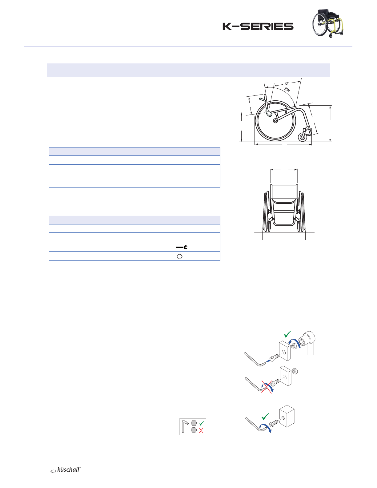
Seat
Tipping point adjustment
The tipping point of the wheelchair can be adjusted by changing the hori-
zontal position of the seat module.
Diculty: Tools: Ã4, 5
Remove the rear wheels, fold the backrest forward and place the
wheelchair on its back.
Loosen the screws , and .
Remove the screws and and slide the seat module forwards or
backwards.
Fix the seat module with the screws and and tighten the screws
, and again.
Carry out the same setting on both sides.
There are 3 possible positions for the rear bracket and 5 possible positions
for the front bracket.
iNote: ensure that the seat brace is as vertical as possible following
an adjustment.
Suspension
A suspension can be tted for a SHh of between 380 and 460.
Fitting a suspension
Diculty: Tools: Ã4, 5
Remove the rear wheels, fold the backrest forward and place the
wheelchair on its back.
Remove the seat module by removing the brackets at the front and
the rear .
Removing the seat brace .
Fit the suspension housing to the frame. Here, slide the screw with
the washer through the suspension housing and place the lubricated
sleeve with the spacer elements on the screw. Slide the screw
through the frame into the axle holder stay and tighten it rmly.
Function check:
It must be possible to rotate the suspension housing , but it must not be
loose.
Insert the suspension seat strut from above into the suspension
housing . Slide the sleeve from below over the suspension seat
strut and position it at the desired seat height. Fix it using the screw
and the washer .
Carry out the same setting on both sides.
Lubricate the springs and insert them into the suspension
housing . Insert the screws into the suspension housing until they
protrude by 25 mm.
Fix the front and rear spring brackets to the seat module (screws a),
insert the lubricated rotating sleeves band x the seat module to the
frame (screws c) again.
Reattach the wheels and stand the wheelchair up again.
Check:
Check the front seat height. When tting the mudguard, ensure that it is at
least 4 mm from the wheel. Check the suspension function.
1
4
2
3
5
7
7
à7 Nm
à7 Nm
à7 Nm
à7 Nm
à13 Nm
1
2
3
4
4
6
7
9
8
6
12
12
13
13
5
10
11
à7 Nm
à4 Nm
aà7 Nm
cà7 Nm