Model350WSB&350WSBWithStandPartsList 5
If you have any questions regarding your warranty rights and responsibilities, you should contact our
CORPORATION Product Support Department for the information.
THINGS YOU SHOULD KNOW ABOUT THE EMISSION CONTROL SYSTEM WARRANTY:
oMAINTENANCEANDREPAIRS
You are responsible for the proper maintenance of the engine. You should keep all receipts and maintenance records
covering the performance of regular maintenance in the event questions arise. These receipts and maintenance
records should be transferred to each subsequent owner of the engine. We reserves the right to deny warranty
coverage if the engine has not been properly maintained. Warranty claims will not be denied, however, solely
because of the lack of required maintenance or failure to keep maintenance records.
MAINTENANCE, REPLACEMENT OR REPAIR OF EMISSION CONTROL DEVICES AND SYSTEMS MAY
BE PERFORMED BY ANY REPAIR ESTABLISHMENT OR INDIVIDUAL; HOWEVER, WARRANTY REPAIRS
MUST BE PERFORMED BY A SERVICE DEALER AUTHORIZED BY US. THE USE OF PARTS THAT ARE
NOT EQUIVALENT IN PERFORMANCE AND DURABILITY TO AUTHORIZED PARTS MAY IMPAIR THE
EFFECTIVENESS OF THE EMISSION CONTROL SYSTEM AND MAY HAVE A BEARING ON THE
OUTCOME OF A WARRANTY CLAIM.
If other than the parts authorized by us are used for maintenance replacements or for the repair of components
affecting emission control, you should assure yourself that such parts are warranted by their manufacturer to be
equivalent to the parts authorized by us in their performance and durability.
HOW TO MAKE A CLAIM
All repair qualifying under this limited warranty must be performed by a service dealer authorized by us. In the
event that any emission-related part is found to be defective during the warranty period you shall notify our
CORPORATION Product Support Department.
3.
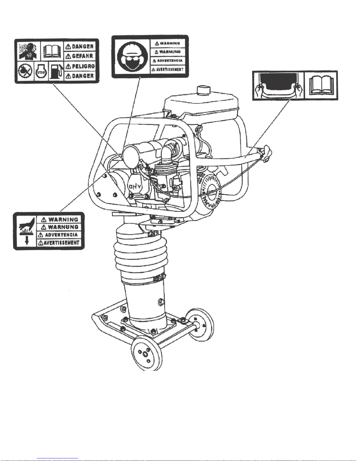
SAFETY INFORMATION
This manual contains DANGER, WARNING, CAUTION, and NOTE callouts which must be followed to reduce the
possibility of personal injury, damage to the equipment, or improper service.
This is the safety alert symbol, It is used to alert you to potential personal injury hazards. Obey all safety messages
that follow this symbol to avoid possible injury or death.
DANGER
indicates a hazardous situation which, if not avoided will result in death or serious injury.
WARNING
indicates a hazardous situation which, if not avoided, could result in death or serious injury.
CAUTION
indicates a hazardous situation which, if not avoided, could result in minor or moderate injury.
CAUTION
: Used without the safety alert symbol,
CAUTION
indicates a potentially hazardous situation
which, if not avoided, may result in property damage.
Note:
Contains additional information important to a procedure.
3.1
OperatingSafety
Familiarity and proper training are required for the safe operation of equipment. Equipment operated improperly
or by untrained personnel can be dangerous. Read the operating instructions contained in both this manual and
the engine manual and familiarize yourself with the location and proper use of all controls. Inexperienced operators
should receive instruction from someone familiar with the equipment before being allowed to operate the machine,
3.1.1
NEVER
operate this machine in applications for which it is not intended.
3.1.2
NEVER
allow anyone to operate this equipment without proper training. People operating this equipment
must be familiar with the risks and hazards associated with it.
3.1.3
NEVER
touch the engine or muffler while the engine is on or immediately after it has been turned off. These
areas get hot and may cause burns.
3.1.4
NEVER
use accessories or attachments that are not recommended by us. Damage to equipment and injury to
the user may result.
3.1.5
NEVER
leave machine running unattended.
3.1.6
NEVER
tamper with or disable the function of operating controls.
3.1.7
NEVER
use choke to stop engine.
3.1.8
NEVER
operate the machine in areas where explosions may occur.
3.1.9
ALWAYS
read, understand and follow procedures in the Operator’s Manual before attempting to operate the
equipment.
3.1.10
ALWAYS
be sure that all other persons are at a safe distance from the machine. Stop the machine if people
step into the working area of the machine.
3.1.11
ALWAYS
be sure operator is familiar with proper safety precautions and operation techniques before using
machine.