KVMSwitchTech AB-5645LCM User manual

DOCUMENT VERSION 1
Instruction Manual
MODEL : AB-5645LCM
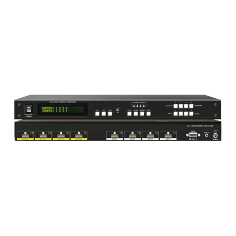
4x4 HDMI MATRIX SWITCHER
HDMI Matrix Switcher Series
Thank you for purchasing the AB-5645 4x4 HDMI Matrix Switcher. You will find this unit easy to install
and highly reliable but it is essential that you read this manual thoroughly before attempting to use 4x4
HDMI Matrix switcher.

1. Save the carton and packing material even if the equipment has arrived in good condition. Should you ever need to ship the unit, use only the
original factory packing.
2. Read all documentation before operating your equipment. Retain all documentation for future reference.
3. Follow all instructions printed on unit chassis for proper operation.
4. Do not spill water or other liquids into or on the unit, or operate the unit while standing in liquid.
5. Make sure power outlets conform to the power requirements listed on the back of the unit.
6. Do not use the unit if the electrical power cord is frayed orbroken. The power supply cords should be routed so that they are not likely to be walked onor
pinched by itemsplaced upon or against them, paying particular attention to cordsand plugs, convenience receptacles, and the point where they exit
from the appliance.
7. Always operate the unit with the AC ground wire connected to the electrical system ground. Precautions should be taken so that the means of
grounding of a piece of equipment is not defeated.
8. Mains voltage must be correct and the same as that printed on the rear of the unit. Damage caused by connection to improper AC voltage is not
covered by any warranty.
9. Power down & disconnect unit from mains voltage before making connections.
10. Never hold a power switch in the "ON" position.
11. Do not use the unit near stoves, heat registers, radiators, or other heat producing devices.
12. Do not block fan intake or exhaust ports. Do not operate equipment on a surface or in an environment which may impede the normal flow of air around
the unit, such as a bed, rug, carpet, or completely enclosed rack. If the unit is used in an extremely dusty or smoky environment, the unit should be
periodically "blown free" of foreign matter.
13. Do not remove the cover. Removing thecover will expose you to potentially dangerous voltages. There are no userserviceable parts inside.
14. Do not drive the inputs with a signal level greater than that required to drive equipment to full output.
15. Non-use periods. The power cord of equipment should be unplugged from the outlet whenleft unused for a long period of time.
16. Service InformationEquipment should be serviced by qualifier service personnel when:
A. The power supply cordor the plug has beendamaged.
B. Objects have fallen, or liquid has beenspilled into the equipment.
C. The equipment has been exposed to rain
D. The equipment does not appear to operate normally, or exhibits a marked change in performance
E. The equipment has been dropped, or the enclosure damaged.
IMPORTANT SAFETY INSTRUCTIONS
To insure the best from this product, please read this manual carefully. Keep it in a safe place for future reference.
To reduce the risk of electric shock, do not remove the cover from the unit. No user serviceable parts inside. Refer servicing to qualified personnel.
To reduce the risk of fire, do not expose the unit to rain, water or excessive moisture.
Do not force switched or external connections.
When moving the unit disconnect the serial port connections first then the power cable and finally the interconnecting cables to other devices.
Do not attempt to clean the unit with chemical solvents or aerosol cleaners, as this may damage the unit. Use a clean dry cloth.
Installation of this unit should be in a cool dry place, away from sources of excessive heat, vibration, dust, moisture and cold.
THIS SAFETY INFORMATION IS OF A GENERAL NATURE AND MAY BE SUPERSEDED BY INSTRUCTIONS CONTAINED WITHIN THIS MANUAL
AB-5645 INSTRUCTION & OPERATION MANUAL PAGE 3

PAGE 4 AB-5645 INSTRUCTION & OPERATION MANUAL
INTRODUCTION
The AB-5645 is high-performance 4x4 matrix routing switcher for HDMI signals. This switcher supports
data rates up to 6.75 Gbps, enabling 1080p HDMI formats and UXGA/WUXGA/DVI resolution to any HD
display. High Definition Digital signals can be selected and distributed to any 4 outputs simultaneously.
The Switcher is certified as being fully HDMI and HDCP compliant, with RoHS,CE,FCC certification.
R R
Support high resolution HDMI sources routed to HDMI displays, monitors, projectors or audio receivers.
The EDID can be selected between seven (8) different modes. Control is provided via Front panel push
buttons, IR remote or via RS-232. An RS232 Windows GUI interface is provided for matrix routing.
PACKAGE CONTENTS
1. Main console unit
2. Operating Instructions
3. IR Remote Controller (SW-5645E)
4. 19 inch Ear mount bracket (Part # 1U-440L)
5. IR Extender receiver (SB-100)
6. CD Contents: This manual, Windows GUI
7. RS232 Cable
8. Power Supply 12VDC, 3A UniversalType 50/60Hz, 100~230 VAC

AB-5645 INSTRUCTION & OPERATION MANUAL PAGE 5
FEATURES
1. 4x HDMI digital source devices matrix switched to 4x HDMI devices.
2. HDMI digital video w/embedded audio, DVI format and CEC/HDCP 2.0 compliant
3. Seven (7) function key control and worldwide EDID modes for HDTV resolutions.
4. Link speeds of up to 6.75 Gbps (link clock rate of 225Mb Hz), Support HDMI 1.4a 3D formats.
5. Wide range of HD resolutions from PC XGA to WUXGA 1920x1200 and
HDTV/DTV resolutions 480i/480p, 576i/576p, 720p, 1080i & 1080p
6. Compatible with all HDMI source devices, PC monitors, Plasma HD display,
HDTV and audio receivers/amplifiers.
7. Digital Video TMDS formats Resolutoin up to 1080P-60 with Deep color 36-bit.
8. Digital Audio Support: - Dolby TrueHD, Dolby Digital, Dolby Digital
Plug/ex, - DTS, DTS-HD, DTS-HD Master, DTS-EX
- PCM, PCM2, LPCM2..
9. Various User Interface control:
Windows based GUI control via RS232 port
Front Panel push button
IR wireless remote control
Third party RS232 controller (via simple ASCII)
10. Support worldwide control functions: ALL/OFF/RECALL/ENTER/MEMORY/EDID/LOCK
11. Support EDID modes :
Internal modes: AUTO/1080P-2CH/1080P-5.1/1080P-7.1/1080i-2CH/720P-2CH
External modes: Passing mode.
12. Automatic scanning input & output status via LED show on front panel.
13. Support IR Remote and IR Extender with distance up to ~ 1000' (300M) Maximum.
14. EDID configuration via internal modes.
15. Consumer Electronic Control (CEC) switch all open or OFF The
Switcher will remember that last state during a power cycle. When
power is removed and resorted, the last configuration will be invoked.

PAGE 6 AB-5645 INSTRUCTION & OPERATION MANUAL

AB-5645 INSTRUCTION & OPERATION MANUAL PAGE 7

PAGE 8 AB-5645 INSTRUCTION & OPERATION MANUAL

AB-5645 INSTRUCTION & OPERATION MANUAL PAGE 9

PAGE 10 AB-5645 INSTRUCTION & OPERATION MANUAL

AB-5645 INSTRUCTION & OPERATION MANUAL PAGE 11

PAGE 12 AB-5645 INSTRUCTION & OPERATION MANUAL

AB-5645 INSTRUCTION & OPERATION MANUAL PAGE 13

PAGE 14 AB-5645 INSTRUCTION & OPERATION MANUAL

AB-5645 INSTRUCTION & OPERATION MANUAL PAGE 15

INSTALLINGDIAGRAM
4x4 HDMI MATRIX SWITCHER
HDMI Projector
HDMI out
AB-6335R
IR-Transmitter
To Projector
IR out
IR Extender Cable
HDMI Extender-RX
CAT5e/6/7 Extension Cable Limited to 330 feet (100M)
4x4 HDMI MATRIX SWITCHER
RoHS
RoHS/95/EC
O U T P U T
2
O U T P U T
1
I N P U T
4
I N P U T
3
I N P U T
2
I N P U T
1
R S 2 3 2
I N P U T
IR EXT. DC 12V
OUTPUT
OUTPUT
4
3
AB-6335T
HDMI in
Extender-Transmitter
IR in
SB-100
IR-Receiver
IR Extender Cable
Blu-ray
PC RS232 Control
IR Extender Cable
SB-100
IR-Receiver
5 6 8 8 I R
CAT5 out
Sample connection using IR Transmitters (SB-101) and IR Receiver (SB-100) with AB-6335T &
AB-6335R to control a projector.
NOTE:
1. Control Projector Over CAT5e/6/7 Extender:
AB-6335 HDMI CAT5e/6/7 Transmitter AB-
6335R HDMI CAT5e/6/7 Receiver
2. Preview Output : Picture as same OUTPUT-1
3. RS-232 Control
4. External IR Remote.
5. IR Extender Transmitter : SB-
101 IR Extender Transmitter.
6. IR Extender Receiver : SB-
100 IR Extender Receiver.

AB-5645 INSTRUCTION & OPERATION MANUAL PAGE 17
Audio Amplifier
CAT5 in HDMI out
AB-6335R
Extender-Receiver
IR Extender Cable
CAT5e/6/7 Extension Cable Limited to 330 feet (100M)
IR in
SB-100
IR-Receiver
Satellite Receiver Remote Control
Audio Extractor
AB-5609
ARC
Audio Mixer
O U T P U T
4
ARC Device
HDMI output to AB-5610
O U T PU T
3
O U T PU T
ARC Control Box
2
AB-5610
O U T P U T
1
ARC
Extender-Transmitter
IR Signal from Satellite
Receiver Remote Control
IR out
AB-6335T
I N P U T
IR Extender Cable
HDMI in
4
CAT5 out
I N P U T
3
I N P U T
2
HD Satellite Receiver
I N P U T
1
4x4 HDMI MATRIX SWITCHER
RS232
I N P U T
IR EXT. DC 12V
RoHS/95/EC
RoHS
INSTALLING DIAGRAM 4x4 HDMI MATRIX SWITCHER
Sample connection using IR Transmitters (SB-101) and IR Receivers (SB-100) with AB-6335T and AB-
6335R to control a Satellite Receiver.
NOTE:
1. Control Satellite Receiver Over HDMI
CAT5e/6/7 Extender from room: AB-
6335T HDMI CAT5e/6/7 Transmitter
SB-6335R HDMI CAT5e/6/7 Receiver
2. Audio Extractor To Recode Audio:
AB-5609 HDMI Audio Extractor.
3. Control HDMI ARC: AB-5610 ARC
Control Box.
4. IR Extender Transmitter: SB-101 IR
Extender Transmitter.
5. IR Extender Receiver: SB-100 IR
Extender Receiver.
Support HDBaseT Extender by AB-6335 Transmitter and AB-6335R Receiver via CAT5e/6/7 cable

PAGE 18 AB-5645 INSTRUCTION & OPERATION MANUAL

AB-5645 INSTRUCTION & OPERATION MANUAL PAGE 19

RS- 232
IR EXT.
SHINYBOW AB-5645
IR Extender to a Room
IR part number : SW-5645
IR Receiver : SB-100 (included)
DISTANCE maximum 300 M / ~ 1000 feet
RoHS/95/EC
INPUT
DC 12V
IR EXTENDER CONNECTION
ROO M
SB-100
ON OFF
1 2 3 4
1 2 3 4
1 2 3 4
1 2 3 4
INPUT -4
4:4HDMIMATRIXSW
SW-5645p
POWER
SB-100
1
INPUT-1
INPUT-2
INPUT-3
IR
PAGE 20 AB-5645 INSTRUCTION & OPERATION MANUAL
Step1
Ring
Sleeve
Tip Ring
Sleeve
Tip (center)
VCC
GND
Cable
Signal
Cable
RoHS/95/EC
I N P U T
D C 1 2 V
RS- 232
IR E XT.
Cable
Step 2 Step 3
SwitcherIREXT.In
HOW TO SETUP THE IR EXTENDER COMPONENTS
Tip:Signal
Ring:VCC
Sleeve:GND
IR Receiver (SB-100)
VCC
GND
Signal
REAR PANEL IR EXTENDER PORT
*** When you plug the External IR extender into the switcher, the front panel IR receiver remains active. ***
IR EXTENDER PACKAGE :
This manual suits for next models
1
Table of contents
Other KVMSwitchTech Matrix Switcher manuals

KVMSwitchTech
KVMSwitchTech AB-4140 User manual

KVMSwitchTech
KVMSwitchTech RKD-KVM-217 Series User manual

KVMSwitchTech
KVMSwitchTech MTX-44-3D User manual

KVMSwitchTech
KVMSwitchTech HD-MTX-88-4KA User manual

KVMSwitchTech
KVMSwitchTech DMS-1616 User manual

KVMSwitchTech
KVMSwitchTech HD-MTX-88-4K User manual

KVMSwitchTech
KVMSwitchTech MVID-MTX88 User manual

KVMSwitchTech
KVMSwitchTech VGA-MTX-88A User manual

KVMSwitchTech
KVMSwitchTech VW-HDMI-4P User manual

KVMSwitchTech
KVMSwitchTech KVM-HD88K User manual