KVMSwitchTech MVID-MTX88 User manual

MVID-MTX Series: Modular Matrix Switcher
V3.7
INSTRUCTION MANUAL
118 W. Streetsboro Street, Ste. 125 | Hudson, OH 44236 | Toll Free: (866) 865-7737
MVID-MTX Modular Matrix Switcher Series
Thank you for purchasing the MVID-MTX Modular Matrix Switcher. You will nd this unit easy to install and highly
reliable but it is essential that you read this manual thoroughly before attempting to use the Modular Matrix Switcher.

SAFETY INFORMATION
1. To ensure the best results from this product, please read this manual and all other documentation before operating your equipment.
Retain all documentation for future reference.
2. Follow all instructions printed on unit chassis for proper operation.
3.
protected from rain, water and excessive moisture.
4. Make sure power outlets conform to the power requirements listed on the back of the unit before connecting.
5. Do not attempt to clean the unit with chemical solvents or aerosol cleaners, as this may damage the unit. Dust with a clean dry cloth.
6. Do not use the unit if the electrical power cord is frayed or broken. The power supply cords should be routed so that they are not
likely to be walked on or pinched by items placed upon or against them, paying particular attention to cords and plugs, convenience
receptacles, and the point where they exit from the appliance.
7. Do not force switched or external connections in any way. They should all connect easily, without needing to be forced.
8. Always operate the unit with the AC ground wire connected to the electrical system ground. Precautions should be taken so that the
means of grounding of a piece of equipment is not defeated.
9. AC voltage must be correct and the same as that printed on the rear of the unit. Damage caused by connection to improper AC
voltage is not covered by any warranty.
10. Turn power off and disconnect unit from AC current before making connections.
11. Never hold a power switch in the “ON” position.
12. This unit should be installed in a cool dry place, away from sources of excessive heat, vibration, dust, moisture and cold. Do not use
the unit near stoves, heat registers, radiators, or other heat producing devices.
13. Do not block fan intake or exhaust ports. Do not operate equipment on a surface or in an environment which may impede the normal
environment, the unit should be periodically “blown free” of foreign dust and matter.
14. To reduce the risk of electric shock, do not remove the cover. There are no user serviceable parts inside. Refer all servicing to
15.
other devices.
16. Do not drive the inputs with a signal level greater than that required to drive equipment to full output.
17. The equipment power cord should be unplugged from the outlet when left unused for a long period of time.
18. Save the carton and packing material even if the equipment has arrived in good condition. Should you ever need to ship the unit,
use only the original factory packing.
19.
A. The power supply cord or the plug has been damaged.
B. Objects have fallen, or liquid has been spilled into the equipment.
C. The equipment has been exposed to rain
D. The equipment does not appear to operate normally, or exhibits a marked change in performance
E. The equipment has been dropped, or the enclosure damaged.
THIS SAFETY INFORMATION IS OF A GENERAL NATURE AND MAY BE SUPERSEDED BY INSTRUCTIONS CONTAINED WITHIN THIS MANUAL

TABLE OF CONTENTS
1
CONTENTS
INTRODUCTION / FEATURES ......................................................2
SPECIFICATIONS .........................................................................3
MAIN UNIT ...................................................................................3
CHANGEABLE CARDS ..............................................................3
FRONT PANEL OPERATION ........................................................4
MVID-MTX88 ...............................................................................4
MVID-MTX....................................................................................5
FRONT PANEL CONTROL ...........................................................6
CHANGEABLE CARDS INTRODUCTION & INSTALLATION .....7
DVI-IN-4 & DVI-OUT-4 ......................................................7
VGA-IN-4 & VGA-OUT-4 ...................................................8
3GSDI-IN-4&3GSDI-OUT-4............................................10
MVID-MTX88 AUDIO CARD ...........................................14
SYSTEM CONNECTION ............................................................15
REMOTE CONTROL ..................................................................16
RS-232 CONTROL ......................................................................17
CONNECTION OF RS-232 COMMUNICATION PORT ............17
REMOTE COMMAND SYSTEM FROM A
PERSONAL COMPUTER ........................................................18
RS-232 COMMANDS ..................................................................19
COMMUNICATION PROTOCOL COMMAND &
COMMAND CODES ....................................................................21
TCP/IP CONTROL ......................................................................23
GUI INTERFACE ........................................................................25
SAFETY OPERATION GUIDE .....................................................27
TROUBLESHOOTING & MAINTENANCE ..................................27
Dear Customer
Thank you for purchasing this product. For optimum performance
and safety, please read these instructions carefully before
connecting, operating or adjusting this product. Please keep this
manual for future reference.
PACKAGE CONTENTS
Before connecting the unit, it is necessary to unpack it from the
shipping carton and inspect the unit for any damage. While the
cards are hot-swappable, it is recommended to install the cards
before connecting the unit. This will make the installation easier.
MVID-MTX Modular Matrix Switcher (w/ empty slot & empty cover)
RS-232 cable
IR remote w/ battery
(4) Plastic cushions
Power Cord
User Manual
SAFETY PRECAUTIONS
Please read all instructions before attempting to unpack, install or
operate this equipment and before connecting the power supply.
Please keep the following in mind as you unpack and install this
equipment:
electrical shock and injury to persons.
moisture or install this product near water.
openings or empty slots in the unit, as you may damage parts
inside the unit.
PSU if it is damaged.
weight to be placed upon it or any person walk on it.
openings in the unit housing that provide ventilation and allow for
DISCLAIMERS
The information in this manual has been carefully checked and
is believed to be accurate. We assume no responsibility for any
infringements of patents or other rights of third parties which may
result from its use.
We assume no responsibility for any inaccuracies that may be
contained in this document. We make no commitment to update or
to keep current the information contained in this document.
We reserve the right to make improvements to this document and/
or product at any time and without notice.
COPYRIGHT NOTICE
No part of this document may be reproduced, transmitted,
transcribed, stored in a retrieval system, or any of its part translated
— electronic, mechanical, magnetic, optical, chemical, manual, or
otherwise — without the express written permission and consent.
© Copyright 2015. All Rights Reserved.
Version 3.7 JULY 2015
Series 2015V2.3
TRADEMARK ACKNOWLEDGMENTS
All products or service names mentioned in this document may be
trademarks of the companies with which they are associated.

2
INTRODUCTION & FEATURES
INTRODUCTION
and 64
output signal sources. It supports different video signals with cross switching. Every video or audio signal is transmitted and switched
independently to decrease signal attenuation (does not support A/V breakaway). MVID-MTX supports various changeable cards including
HMDI, DVI, VGA, SDI and HDBaseT™ etc, and all the cards support hot plug & play. Users can choose to insert different signal cards
for different applications.
port for serial control and optional IP port for TCP/IP control, can be easily controlled by third-part devices.
multimedia conference rooms, control rooms, broadcasting rooms, shopping center etc. It will handle all the audiovisual management,
including the switching, driving, scaling etc.
MVID-MTX Modular Matrix Switcher Models
Models Height Maximum Slot Power supplies RS-232 control Audio I/O Network control
MVID-MTX88 2U 2 input card slots &
2 output card slots Single üYes* Optional
MVID-MTX1616 3U 4 input card slots &
4 output card slots Dual üNo Optional
MVID-MTX3232 5U 8 input card slots &
8 output card slots Dual üNo Optional
MVID-MTX6464 10U 16 input card slots &
16 output card slots Dual üNo Optional
*The MVID-MTX88 is unique in this series in that it comes with (8) analog audio Inputs and (8) analog audio Outputs already installed.
independently from other channels. For example, when you route HDMI Input 2 to HDMI Output 3, the analog audio Input 2 will also route
to analog audio Output 3. This card is not available as a separate card for installation into the other chassis.
On ALL models (including MVID-MTX88) cards that have external audio I/O, you can select between the different audio Input sources.
For example, the HDBaseT™ Input card has HDMI with embedded audio, and a 3.5mm analog stereo audio port. Using RS-232
commands, you can select the audio source as embedded or external. On the Output card, the embedded and external audio will be the
same. You cannot do Audio/Video breakaway.
FEATURES
Various I/O cards, includes HDMI, HDBaseT™, SD/HD/3G-SDI, DVI and VGA cards (Compatible with YUV, YC, CVBS & CVBC) to
Truly cross-point switching, any input to any output, regardless of signal format
Supports HDMI1.4a, supports 3D & HDCP compliant
Integrated HDBaseT™ technology
Controllable via front panel push buttons, RS-232 & optional TCP/IP, also compatible with 3rd party controlers
LCD display

3
SPECIFICATIONS
Main Unit
Control Parts General
Serial Control Port RS-232, 9-pin female D connector Power Supply
Installation Rack Mountable Temperature 14~104°F (-10 ~+40°C)
2 = TX, 3 = RX, 5 = GND Power Consumption 200W (max)
Front panel control Buttons Humidity 10% ~ 90%
Options TCP/IP control by external device. Switcher does not
include a build-in web server.
Case Dimension (WxHxD) Product Weight
MVID-MTX88 19 x 3.5 x 12.6 in (483x88x320mm) (2U high)
MVID-MTX1616 19 x 5.25 x 12.6 in (483x133x320mm) (3U high)
MVID-MTX3232 19 x 8.7 x 12.6 in (483x222x320mm) (5U high)
MVID-MTX6464 19 x 17.25 x 12.6 in (483x438x320mm) (10U high)
While cable distance is dependent on the quality of the cable that you use and the resolution, here is a general reference:
Cable Distance
HDMI 50 feet 15M
VGA 65 feet 20M
DVI 23 feet 7M
HDBaseT™ 230 feet 70M
MVID-MTX signal card (changeable cards)
MVID-MTX Input cards MVID-MTX Output cards
MODELS INPUTS SIGNAL FORMAT Models OUTPUTS Signal Format
DVI-IN-4 4 DVI DVI-OUT-4 4 DVI
VGA-IN-4 4 VGA & STEREO AUDIO VGA-OUT-4
4 VGA,
4 STEREO
AUDIO
VGA & ANALOG AUDIO
3GSDI-IN-4
4 Inputs &
4 LOOP
Outputs
for each
channel)
SDI 3GSDI-OUT-4
4 Outputs
& 4 LOOP
Outputs
for each
channel)
SDI
4HDMI & STEREO
AUDIO 4HDMI & STEREO
AUDIO
4 OPTICAL FIBER 4 OPTICAL FIBER
4HDBaseT™, RS-232,
AUDIO 4HDBaseT™, RS-232,
AUDIO

4
MVID-MTX88
Front Panel Operation
MVID-MTX88: The front panel of MVID-MTX88 is shown as below.
1. IR: IR sensor, receive IR signal sent from IR remote
2. POWER INDICATOR: Illuminate red once powered on
3. LCD SCREEN: Display real-time operation status
4. INPUTS: Buttons for input channels with green back-light indicating, ranges from 1~ 8, (8) selectable channels in total
5. OUTPUTS: Buttons for output channels with green back-light indicating, ranges from 1 ~ 8, (8) selectable channels in total
6. AV: Transfer video and audio signal synchronously
ALL: Select all input/output channel
THROUGH: To transfer the signals directly to the corresponding output channels
UNDO: Undo button, to resume to the status before the command just performed
←:Backspace - to backspace the latest press
BACK Panel Operation
1. INPUTS: Audio input slot
2. OUTPUTS: Audio output slot
3. INPUTS: Input signal card slots, (2) in total
4. OUTPUTS: Output signal card slots, (2) in total
5. POWER PORTS: Connect with household alternating current power
6. RS-232: Serial control port, connect with RS-232 port of control device
7. GND CONNECTOR: Used for system grounding
8. TCP/IP (Optional): Used for TCP/IP control port
Note: There are only (2) input and (2) output slots for MVID-MTX88, which enables only (2) input cards and (2) output cards to
be installed. The input/output cards can be changed based on your requests and supports hot plug and play.
q
w
e
r
t
y
q w
er
t
y
u

5
FRONT & back PANEL
Front Panel Operation
MVID-MTX1616/MVID-MTX3232/MVID-MTX6464: The switcher models MVID-MTX1616, MVID-MTX3232, and MVID-MTX6464 share the
as below.
1. IR: IR sensor, receive IR signal sent from IR remote
2. POWER INDICATOR: Illuminate red once powered on
3. LCD SCREEN: Display real-time operation status
4. INPUTS: Buttons for input channels with green back-light indicating, ranges from 0~ 9, 32 selectable channels in total
5. OUTPUTS: Buttons for output channels with green back-light indicating, ranges from 0 ~ 9, 32 selectable channels in total
6. MENU AV: Transfer video and audio signal synchronously
,: division button, to divide the output channels when switching to more than one channel
ENTER:
ALL: To transfer an input channel to all output channels
THROUGH: To transfer the signals directly to the corresponding output channels
UNDO: Undo button, to resume to the status before the command just performed
←:Backspace - to backspace the latest press
BACK Panel Operation
1. INPUTS: Input signal card slots
2. OUTPUTS: Output signal card slots
3. POWER SWITCH: Switch between AC110V and AC230V to access different power
4. POWER PORTS: Connect with household alternating current power, including one redundant power
5. RS-232: Serial control port, connect with RS-232 port of control device
6. TCP/IP (Optional): Used for TCP/IP control port
q
w
e
r
t
y
qwe
r
t
y

6
FRONT PANEL control
Front Panel Button control
MVID-MTX88
Users can control MVID-MTX88 rapidly and directly with its front panel buttons. Here is a brief operation guide to front panel buttons.
Format: “Input Channel” + “Switch Mode” +“Output Channel”
Note:
1. “Switch Mode”: Audio & Video synchronal (AV) or separate switching mode (Audio/ Video)
2. “Input Channel”: Fill with the number of input channel to be controlled
3. “Output Channel”: Fill with the number of output channels to be controlled. Press “All” to select all the outputs
4. The input/output channels on the rear panel are counting from left to right, top to bottom
5.
will be cancelled.
Example:
1. To transfer input (1) to output (11), press input “1”, output “0” “1”.
2. To transfer signals from input (1) to all output channels, press buttons in this order: “1”, “All”.
Functional Buttons:
UNDO Button: return to the previous status
Example: Input (6) is connecting with output (6), press input “6” + “AV”+ output 4 to change the connection. Press “Undo” to
enable input (6) to reconnect with output (6).
←Button: If you press buttons “1”, “AV”, “2”, “←” in order, then “2” will be canceled.
THROUGH Button: get straight I/O connection, e.g. input 1 > output 1, input 2 > output 2. Press “Input Channel”+”Through”
Example: If you press buttons “ALL”, “THROUGH” in order, then the result will be like input 1 > output 1, input 2 > output 2,
input 3 > output 3 … input 8 > output 8.
MVID-MTX
Users can control the MVID-MTX rapidly and directly with its front panel buttons. To switch AV/ A/ V signal, please operate the buttons
under the following format:
Format: “Input Channel” + “AV” +“Output Channel”+“Enter”
Note:
1. “Switch Mode”: Audio & Video synchronal (AV) or separate switching mode (Audio/ Video)
2. “Input Channel”: Fill with the number of input channel to be controlled
3. “Output Channel”: Fill with the number of output channels to be controlled. Press “All” to select all the outputs
4. “,” Button: Use to separate multiple I/O channels, and press “ENTER”
5. The input/output channels on the rear panel are counting from left to right, top to bottom.
6.
will be cancelled.
Example:
1. To transfer input (1) to output (11), press input “1”, output “0” “1”.
2. To transfer signals from input (1) to all output channels, press buttons in this order: “1”, “All”.
Functional Buttons:
UNDO Button: return to the previous status
Example: Status 1: Input 6 > output 6
Press input “6” + “AV”+ output 4 to change the connection. Press “Undo” to return to Status 1.
←Button: Backspace the last operation
Example: If you press buttons “1”, “AV”, “2”, “←” in order, then “2” will be canceled.
THROUGH Button: Get straight I/O connection, e.g. input 1 > output 1, input 2 > output 2. Format: “Input Channel”+”Through”
Example: If you press buttons “ALL”, “THROUGH” in order, then the result will be like input 1 > output 1, input 2 > output 2,
input 3 > output 3 … input 16 > output 16.

7
CHANGEABLE CARDS
Changeable Cards Introduction & Installation
The various MVID-MTX chassis units are designed to work with various changeable input/ output cards, which can be installed in any
VGA, HDBaseT™, and SDI.
DVI Card
DVI-IN-4 & DVI-OUT-4
Input Output
Input (4) DVI Output (4) DVI
Input Connector Female DB24+5 Output Connector Female DB24+5
Input Level T.M.D.S. 2.9V/3.3V Output Level T.M.D.S. 2.9V/3.3V
Input Impedance Output Impedance
General
Gain 0 dB Bandwidth
Video Signal DVI 1.0/HDMI 1.3 full digital T.M.D.S
signal
Switching Speed 200ns (Max)
Crosstalk Max Time-delay 5nS (±1nS)
EDID and DDC
and HDMI standards. EDID and DDC signals are actively buffered
HDCP Compliant with HDCP using DVI and HDMI 1.3 standards
Fully compatible with HDMI 1.3 and HDCP, but does not support analogy signal
Embedded EDID management technology, supporting DDC
DVI-IN-4: Is an input card which accepts a maximum of (4) separate DVI input signals. Input signals can be passed to output devices
through DVI-OUT-4, or passed through to other types of outputs, through other output cards in the series.
DVI-OUT-4: Is an output card, which provides a maximum of (4) separate DVI output signals. Input signals can come from an DVI-IN-4,
or from other kinds of input cards in the series.
Pin Layout of the DVI-I connector (Dual-Link). (Female)
PIN Function PIN Function PIN Function
1 T.M.D.S.Data2- 9 T.M.D.S.Data1- 17 T.M.D.S. Data 0-
2 T.M.D.S.Data2+ 10 T.M.D.S.Data1+ 18 T.M.D.S. Data 0+
3 T.M.D.S. Data 2/4 Shield 11 T.M.D.S.Data1/3 Shield 19 T.M.D.S. Data 0/5 Shield
4 T.M.D.S. Data 4- 12 T.M.D.S.Data3- 20 T.M.D.S.Data5-
5 T.M.D.S. Data 4+ 13 T.M.D.S.Data3+ 21 T.M.D.S.Data5+
6 DDC Clock 14 +5V Power 22 T.M.D.S. Clock Shield
7 DDC Data 15 Ground (return for +5V,
Hsync and Vsync)
23 T.M.D. S. Clock +
8 Analog Vertical Sync 16 Hot Plug Detect 24 T.M.D.S .Clock-

8
CHANGEABLE CARDS
VGA Signal Card
VGA-IN-4/VA-IN-4 & VGA-OUT-4
Video Input Video Output
Input (4) VGA Output (4) VGA
Input Connector Female 15 pin HD Output Connector Female 15 pin HD
Input Level 0.5 ~ 2.0Vp-p Output Level 0.5 ~ 2.0Vp-p
Input Impedance Output Impedance
Audio Input Audio Output
Input (4) STEREO AUDIO Output (4) STEREO AUDIO
Input Connector 3P Captive connector Output Connector 3.5mm Stereo audio connector
CMRR CMRR
Input Impedance Output Impedance
General
Gain 0 dB Bandwidth
Video Signal VGA-UXGA, RGBHV, RGBS, RGsB, RsGsBs, component video, S-video & composite video
Crosstalk Switching Speed 200ns (Max)
EDID and DDC
and HDMI standards. EDID and DDC signals are actively buffered
HDCP Compliant with HDCP using DVI and HDMI 1.4a standards
Scales all inputs to 1080p
Compatible with C-Video, YUV, YC (Factory preset function)
Supports RGBHV, RGsB, RGBS, RsGsBs, YUV, YC and Composite video
VGA-IN-4: Is an input card which accepts a maximum of (4) separate VGA inputs and (4) stereo audio inputs. Input signal can pass to output
VGA-OUT-4: Is an output card, which provides a maximum of (4) separate VGA output signals.
Pin layout of the VGA connectors (female):
PIN Signal Name PIN Signal Name
Pin 1 RED Pin 9
Pin 2 GREEN Pin 10 GND
Pin 3 BLUE Pin 11 ID0/RES
Pin 4 ID2/RES Pin 12 ID1/SDA
Pin 5 GND Pin 13 HSync
Pin 6 RED_RTN Pin 14 VSync
Pin 7 GREEN_RTN Pin 15 ID3/SCL
Pin 8 BLUE_RTN

9
CHANGEABLE CARDS
Connect the devices via VGA converting cable as shown:
Connect with Component Video (YPbPr) Source
Connect with Composite Video (C-VIDEO) Source
*(4) Male VGA to female YPbPr cable (Only included with the VGA-IN-4/ANI-IN-VA cards)
*(4) Male VGA to female S-video & RCA (C-video) cable (Only included with the VGA-IN-4/ANI-IN-VA cards)
Component Video Dongle
S-Video or Composite Video Dongle

10
CHANGEABLE CARDS
SDI Signal Card
3GSDI-IN-4 & 3GSDI-OUT-4
Input Output
Input (4) SDI Output (4) SDI
Input Connector Female BNC Output Connector Female BNC
Input Level 0.8Vp-p ± 10% Output Level 0.8Vp-p ± 10%
Input Impedance Output Impedance
General
Gain Unity Transmission Distance 300M (Max)
Video Standard SMPTE 292M, SMPTE 259M, SMPTE 424M, ITU-RBT.601, ITU-RBT.1120
Audio Bits per Sample 18 bits per channel, 2 channels (L, R)
Input Return Loss Maximum Data Rate 2.97 Gbps
Data Rate Lock Auto Data Type 8bit, 10bit
Compatible with various different SDI signal formats, including SD/HD/3G-SDI (adaptive)
Every port has looping output for local monitoring
3GSDI-IN-4: Is an input card which accepts a maximum of (4) separate SDI input signals. Input signal can be passed to output device
through 3GSDI-OUT-4, or passed through other output cards in the series. This card is unique when compared to the other input cards in
that it provides a “through” connection for daisy-chainging video devices. Each input signal can be immediately sent back out (“looping”
it), without switching capability, to go to individual monitors.
3GSDI-OUT-4: Is an output card which provides a maximum of (4) separate SDI output signals. Input signals can come from an 3GSDI-IN-4,
or from other kinds of input cards in the series.
The BNC connector is shown as the gure below.

11
CHANGEABLE CARDS
HDBaseT™ Card
HDBT-4K-IN-4 & HDBT-4K-OUT-4
Input Output
Input (4) RJ45 Output (4) RJ45
Input Connector Female RJ45 / 3.5mm mini jack for IR
(3) poles captive screw connector
for RS-232
Output Connector Female RJ45 / 3.5mm mini jack for IR
(3) poles captive screw connector
for RS-232
Input Impedance Output Impedance
General
Gain Bandwidth 6.75Gbps
Resolution Range 800x600 ~ 1920x1200 Transmission Distance 70M(Max)
SNR Return Loss
THD Min. ~ Max. Level < 0.3V ~ 1.45Vp-p
HDMI Standard Support HDMI1.4 and HDCP Differential Phasic Error
Supports hot-plug, HDTV, compatible with HDBaseT™ 1.0, HDMI 1.4a & HDCP 1.4
Wide resolution range from 480p to 4K2K, 1080p 3D compliant
Extends HDBaseT™ signal up to 70M at 1080p or 40M at 4K2K
Bi-directional RS-232 transmission on single cable
Auxiliary audio ports support stereo signal
Embedded EDID management technology
HDBT-4K-IN-4: Is an input card which accepts a maximum of input (4) separate HDMI signals. Input signals can be passed to output
an TRA-HDB-2P HDBaseT™ Transmitter*.
HDBT-4K-OUT-4:
IN-4, or from other kinds of input cards in the series. This card needs to work in conjunction with an REC-HDB-2P HDBaseT™ Receiver*.
channel. They do not have to be used for the HDBaseT™ channel to function, but are provided for those situations where they are
Pin layout of the RJ45 connectors:
use the same standard.
TIA/EIA T568A TIA/EIA T568B
PIN CABLE COLOR PIN CABLE COLOR
1 green white 1 orange white
2 green 2 orange
3 orange white 3 green white
4 blue 4 blue
5 blue white 5 blue white
6 orange 6 green
7 brown white 7 brown white
8 brown 8 brown
*For more information on the TRA-HDB-2P and REC-HDB-2P please see our website.
When using STP, Cable
connectors MUST be
metal, and the shielded
layer of cable MUST
be connected to the
connector’s metal
shell, to well share the
grounding.

12
CHANGEABLE CARDS
HDMI 4K2K Card
HDMI-4K-IN-4 & HDMI-4K-OUT-4
Video Input Audio Input
Input (4) HDMI Input (4) ANALOG
Input Connector Female HDMI Input Connector 3.5mm pluggable terminal block
Min.~ Max. Level T.M.D.S. 2.9V~3.3V Input Impedance
Input Impedance Frequency Response
Video Output Audio Output
Output (4) HDMI Output (4) STEREO
Output Connector Female HDMI Output Connector 3.5mm Stereo audio connector
Min.~ Max. Level T.M.D.S. 2.9V~3.3V Output Impedance
Output Impedance Frequency Response
General
Gain Bandwidth 6.75Gbps
Max Resolution Crosstalk
Transmission Distance Switching Speed 200ns (Max)
Work Temperature -10°C~ +40°C Reference Humility 10%~90%
SNR Return Loss
Supported Audio Format Embedded HDMI Audio: Stereo, Dobly Digital, DTS, DTS-HD / Analog Audio: Stereo only
HDMI Standard Supports HDMI 1.4& DVI 1.0
DID& HDCP
Management
Compliant with HDCP 1.4 / Supports manual EDID management
Supports hot-plug, HDMI 1.4 & HDCP 1.4 compliance
Compatible with DVI signal
Provides auxiliary audio port as supplement to HDMI embedded audio
Embedded EDID management technology
HDMI-4K-IN-4: Is an input card which accepts a maximum of input (4) separate HDMI signals. Input signals can be passed to output
HDMI-4K-OUT-4:
IN-4, or from other kinds of input cards in the series. HDCP compliant status settable via RS-232 commands.
Pin layout of the HDMI connectors (Female)
PIN Signal Name PIN Signal Name PIN Signal Name
1 TMDS Data 2+ 8 TMDS Data 0 Shield 15 DDC Clock
2TMDS Data 2 Shield 9 TMDS Data 0- 16 DDC Data
3 TMDS Data 2- 10 TMDS Clock+ 17 Ground
4 TMDS Data 1+ 11 TMDS Clock Shield 18 +5V Power
5TMDS Data 1 Shield 12 TMDS Clock- 19 Hot Plug Detect
6 TMDS Data 1- 13 CEC 20 SHELL
7 TMDS Data 0+ 14 No Connect

13
CHANGEABLE CARDS
4K2K FIBER Card
4K2KF-IN-4 & 4K2KF-OUT-4
Input Output
Input (4) Fiber Optical Output (4) Fiber Optical
Input Connector SPF Fiber Optical Connector Output Connector SPF Fiber Optical Connector
Fiber Type Multi-mode, Single mode Fiber Type Multi-mode, Single mode
General
Data Rate 10.2 Gbps Color Depth 8bit, 10bit, 12bit, 16bit
Work Temperature 0°C~55°C Reference Humility 10%~90%
Optical Fiber Mode
Connector LC connector Resolution
Transmission Distance
300M (Multi-mode transmission, using Single/ Multi mode Optical Module and OM3 Multi-Mode Fiber Cable)
Data Rate 10.2Gbit/s
Compliant with HDMI 1.4
Capable to transmit 4K2K & 1080p 3D (max) signals
4K2KF-IN-4: Is an input card which accepts a maximum of input (4) separate signals. Corresponding indicator illuminates green when
4K2KF-OUT-4:
from other kinds of input cards in the series. Corresponding indicator illuminates green when there is output signal.
Note: Use the 4K2KF-IN-4 & 4K2KF-OUT-4 with an optical ber transmitter/receiver.

14
AUDIO CARDS
AUDIO Card
MVID-MTX88 Only
Input Output
Input (8) STEREO Output (8) STEREO
Input Connector 3.5mm captive screw connectors (5) pole Output Connector 3.5mm captive screw connectors (5) pole
Input Impedance Output Impedance
General
Frequency Response CMRR
Stereo Channel
Separation
THD + Noise
8x8 stereo audio cross point switching card
Supports the balanced/unbalanced audio, by different connection
It is NOT
Balanced Audio Connection:
Unbalanced Audio Connection:

15
REMOTE CONTROL
IR Remote control
With the IR remote, MVID-MTX could be controlled remotely. As the function buttons on the IR remote are the same with the ones on the
front panel, the IR remote shares the same operations and commands with the control panel.
Press the buttons under below format:
“Input Channel” + “Switch Mode” +“Output Channel”
Input channel
buttons,
including 1~10+
Menu buttons,
including
switching buttons
and function
buttons
Output channel
buttons,
including 1~10+

16
System Connection
Usage Precautions
1. System should be installed in a clean environment and has a prop temperature and humidity.
2. All of the power switches, plugs, sockets and power cords should be insulated and safe.
3. All devices should be connected before power on.
Connection Diagram
Application
MVID-MTX series has a good application in various occasions, such as radio & television, multi-media meeting room, big screen displaying,
television education and command & control center etc.

17
RS-232 Control
Connection of RS-232 Communication Port
Besides the front control panel and IR remote, the MVID-MTX can also be controlled by far-end control system or through the Ethernet
shown in the table below.
NO. PIN FUNCTION
1 N/u Unused
2 Tx Transmit
3 Rx Receive
4 N/u Unused
5 Gnd Ground
6 N/u Unused
7 N/u Unused
8 N/u Unused
9 N/u Unused
When the MVID-MTX connects to the RS-232 port of a computer with control software, users can control it by that computer. To control
the switcher, users need to use RS-232 control software.
http://www.kvmswitchtech.com/32x32-multi-video-format-matrix-switch-with-hdmi-dvi-sdi-vga-ber-optic-support-and-tcpip-control-p50198.htm

18
RS-232 Control
Remote Command System from a Personal Computer
The MVID-MTX Matrix series can be controlled remotely from a personal computer. The control signal is brought into the MVID-MTX
Matrix through the RS-232 connector on the back panel of the unit. The commands are input through software that comes with the MVID-
MTX Matrix, once installed in the computer.
RS-232 Cable Pins Used
Communications Protocol:
1. Transmission Rate: 9600 bps
2. Data Format: 8 data bits, No parity , 1 start bit, and 1 stop bit
3. Flowing Control: None
Also known as: 9600,8,n,1
Proper settings for the computer’s communication protocol are shown in the screen shots below:
This manual suits for next models
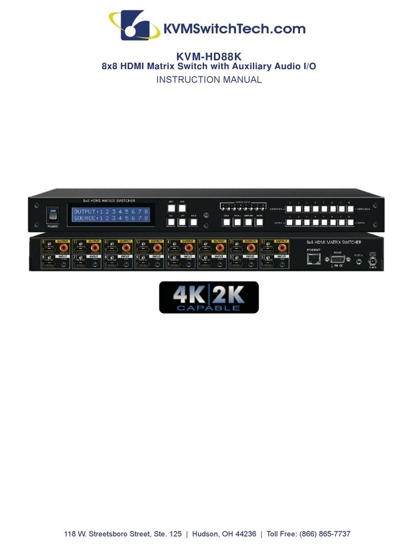
3
Table of contents
Other KVMSwitchTech Matrix Switcher manuals

KVMSwitchTech
KVMSwitchTech DMS-1616 User manual

KVMSwitchTech
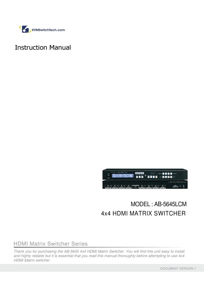
KVMSwitchTech AB-5645LCM User manual

KVMSwitchTech
KVMSwitchTech AB-4184 User manual

KVMSwitchTech
KVMSwitchTech VW-HDMI-4P User manual

KVMSwitchTech
KVMSwitchTech KVM-HD88K User manual

KVMSwitchTech
KVMSwitchTech MTX-44-3D User manual

KVMSwitchTech
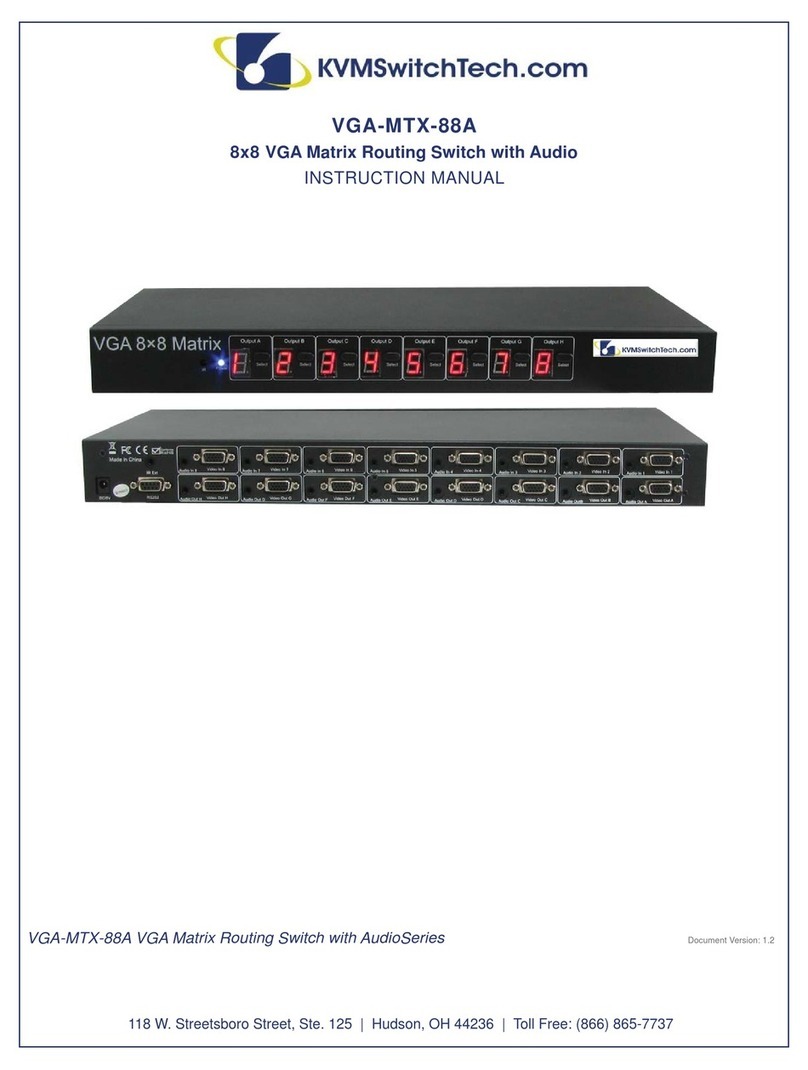
KVMSwitchTech VGA-MTX-88A User manual

KVMSwitchTech
KVMSwitchTech AB-4140 User manual

KVMSwitchTech
KVMSwitchTech HD-MTX-88-4K User manual

KVMSwitchTech
KVMSwitchTech HD-MTX-88-4KA User manual