Polish terminal part of battery
pack with dry cloth, etc
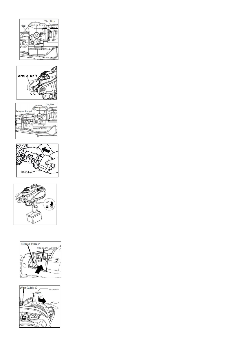
Turn off power, remove binding
wire inside curl guide
Either wipe Cutter section with dry
cloth or blow it with air
Diassemble the cutter section and
remove the caught wire
Pay attention so that wire does not
hit reinforcing bars at binding
Either wipe Cutter section with dry
cloth or blow it with air
Pay attention so that wire does not hit
reinforcing bars at binding.
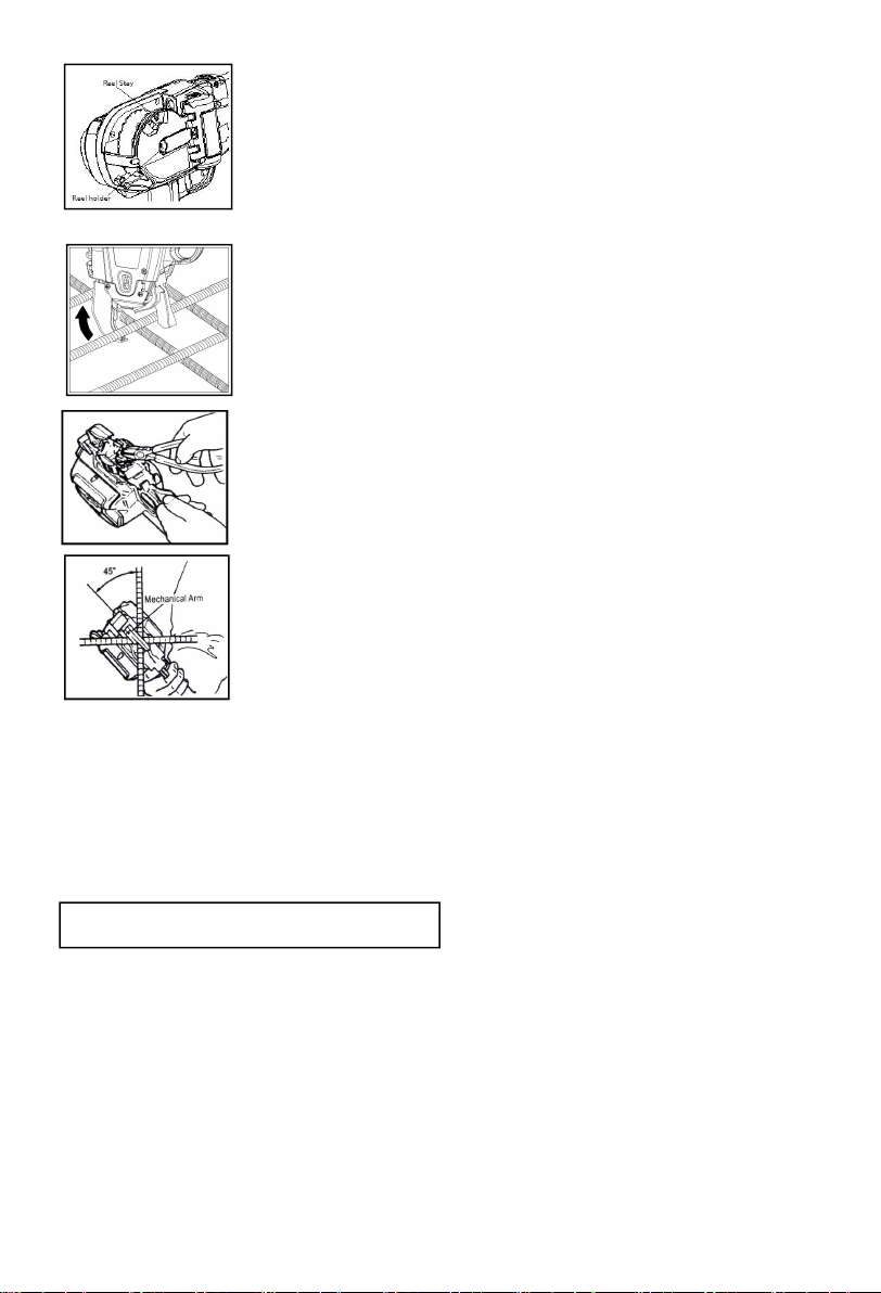
Use approriate diameter scope
Adjust the Torque to a higher lever
and insert in vertical direction. use
as tilting at45°
Use approriate diameter scope
Adjust the Torque to a lower lever
and insert in vertical direction. use
as tilting at45°
Leave the tool and the battery pack
at normal temperature in the room
for some time. and then continue the
operation.
Confirm the battery is charged.
Take out the battery and see if the
electrode has been brown.
Turn off power and take out the
battery to confirm if binding wire has been
entangled inside curl guide.
Confirm the battery is charged
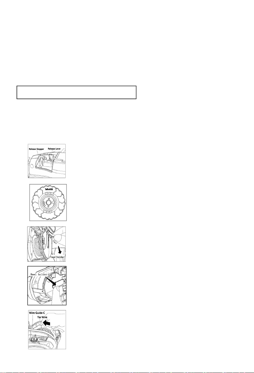
Check if the Tie-wire has been run
Check if wire inside reel has been
loosened and caught
Confirm functioning of Cutter section
Check if any wire is caught.
check if wire hits reinforcing bars at binding
Confirm function of Cutter section.
Check if wire hits reinforcing bars at binding
Confirm size of reinforcing bars to be bound
Confirm how to apply machine to
reinforcing bars
Confirm size of reinforcing bars to be bound
Confirm how to apply machine to reinforcing
bars
Confirm the battery is fully charged.
Check the temperature at the job site.
Electrode plate has been
oxidized
Binding wire has been
entangled around Twist section.
Tie-wire has been run out
Cutter section is blocked with foreign
substance
A wire is caught in the cutter section or
Wire guide A
Wire, by hitting reinforcing
bars, was repelled
Cutter section is blocked with foreign
substance
Wire, by hitting reinforcing
bars,was repelled
Reinforcing bars is not of
designated size.
Erroneous handling such as
improper application of
machine
Reinforcing bars is not of
designated size
Erroneous handling such as improper
application of
machine
Low power remains in the
battery pack
The tool is used at high temperature.
Continuous short
beeps(Pi,pi,pi…)
Three short beeps
repeated(Pi,pi,pi,Pi,pi,pi,
…)
Two long beeps
repeated(Pi-pi, pi-pi,...)
Four short beeps
repeated(Pipipipi,
Pipipipi,…)
Curl is
disordered and
steps out of curl
No wire cutting takes
place.
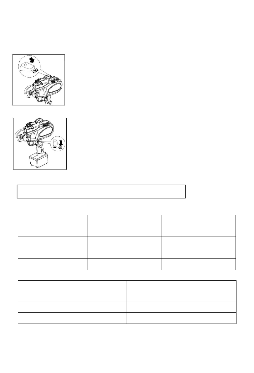
Power ON→ The Tip
Axis is initialized
and the wire-cutter
operates
automatically.
Trigger ON→
Wire is sent out.
Binding wire
draws a circle.
Wire is subject to
cutting