Kyocera TJEP 17/15-2 Guide

www.tjep.eu
UK Safety and operation instructions
Maintenance and trouble shooting
BG Инструкции за безопасност и работа
Поддръжка и отстраняване на неизправности
DA Sikkerheds- og driftsvejledning
Vedligeholdelse og fejlfinding
DE Sicherheits- und Bedienungsvorschriften
Instandhaltung und Fehlerbehebung
EE Ohutus- ja kasutusjuhised
Hooldus ja tõrkeotsing
FR Instructions de sécurité et d’utilisation
Maintenance et dépannage
IS Öryggis- og notkunarleiðbeiningar
Viðhald og bilanaleit
LT Saugos ir naudojimo instrukcijos
Priežiūra ir trikčių šalinimas
NL Veiligheids- en bedieningsinstructies
Onderhoud en probleemoplossing
NO Sikkerhets- og bruksanvisning
Vedlikehold og feilsøking
PL Instrukcja bezpieczeństwa i obsługi
Konserwacja i rozwiązywanie problemów
RO Instrucțiuni de siguranță și operare
Întreținere și depanare
SE Säkerhets- och driftinstruktioner
Underhåll och felsökning
SK Bezpečnostné a prevádzkové pokyny
Údržba a riešenie problémov
SL Varnostna navodila in navodila za uporabo
Vzdrževanje in odpravljanje težav
TJEP 17/15-2

www.tjep.eu
EXPLORE OUR WEBSITE FOR
MORE INFORMATION

UK Drawing and spare parts................................................................................4
Key parts and gures .....................................................................................7
UK English............................................................................................................8
BG Български....................................................................................................16
DA Dansk ...........................................................................................................25
DE Deutsch ........................................................................................................33
EE Eesti..............................................................................................................42
FR Français........................................................................................................50
IS Íslenska ........................................................................................................58
LT Lietuvis.. .......................................................................................................66
NL Nederlands...................................................................................................74
NO Norsk ............................................................................................................82
PL Polski............................................................................................................90
RO Română........................................................................................................98
SE Svenska......................................................................................................106
SK Slovenský................................................................................................... 114
SL Slovenščina................................................................................................122
3

4
TJEP 17/15-2
13
EXPLODED VIEW

English
5
13
EXPLODED VIEW

6
Spareparts
ITEM
NO.
PART NO. DESCRIPTION
1 X4487370187 Accessory Holder
2 Q4487362135 Accessory Storage Box
Cover
3 F6413700920 Rubber Hose
4 F3013700919 Pressure Regulator
5 J0023160647 Safety Valve
6 J0784290032 Screw M4x12
7 J5637160032 End Cap
8 F5013700908 Pressure Gauge
9 J2993490675 Quick Coupler
10 Q4486012135 Control Panel
11 Q3766408007 Slide Sleeve
12 Q42021111331 Pressure Regulator
Knob
13 J0782730032 Screw M4x10
14 J0783570033 Screw M5x12
15 J0800470033 Screw M6x35
16 Q3766398001 Nut
17 Q3766388001 Latch assm ( L )
18 J0200580003 Spring
19 Q3762988001 Plastic Washer
20 J3890570211 Lever
21 J2020530033 Lock Nut
22 Q42010270011 Handgrip
23 Q3766378001 Latch assm ( R )
24 J3264600752 Handle
25 D3005000142 Pressure Switch
26 J0780600033 Head Screw M8x8
27 D1006083181 Power Cord
28 J3434590048 Tranfer Tube
29 J0189940407 Check Valve
30 J7383090034 Capacitor Shroud
31 X4207350167 Capacitor Fixed Ring
32 J3095040201 Air Filter
33 J0783480674 Self-Tapping Screw
ST3.9x16F
ITEM
NO.
PART NO. DESCRIPTION
34 D6015001024 Capacitor
35 D5010003001 Crimp Cap
36 F0000901043 Heat Shield Assembly
37 Q411A263001 Silencing tube
38 J3161200423 Elbow Fitting
39 A5538911057 Motor Pump Assembly
40 J0994540201 Metal Tube
41 X0004360212 Cushion Pad
42 J2020810033 Flange Nut M8
43 J2852990033 Shoulder Bolt
44 X3060600037 Wheel
45 Z1240000256 Clamp
46 J0782380299 Screw ST4.8x14
47 J2981850040 Flat Washer Ø10
48 J0191860022 Washer Ø10
49 J2021830040 Flange Nut M10
50 Q3515632001 Plastic End Cap
51 J0783470485 Self-Tapping Screw
ST3.9x16F
52 J0807660040 Screw M8x14
53 AT1620.00.00.01 Tank
54 J0907040313 Drain Valve
55 J0780600033 Washer Ø8
56 X4200590169 Rubber Foot
57 J0783570033 Head Screw M5x12
58 J5638170344 End Cap
59 Q4487332135 Toolbox Components

7
Figures
Fig. A
1
2
3
31 cm
Fig. B
2
1
Fig. C
1ON/OFF
Fig. D
1
OFF
ON
Fig. E
1
Fig. F Fig. G Fig. H
2
1
OFF
ON
Fig. I
Key parts
5
KEY PARTS DIAGRAM
K. Power Cord
E. Pressure Regulator Knob
G. Tank Pressure Gauge
F. Outlet Pressure Gauge
D. Pressure Switch
H. Quick CouplerB. Air Compressor Pump
A. Electrical Motor
J. Air Tank
I. Drain ValveC. Safety Valve
A
H
GEFD
K
I
B
C
J

8
IMPROPER AND UNSAFE USE OF THE COMPRESSOR CAN RESULT IN DEATH OR SERI-
OUS INJURY. IT IS VERY IMPORTANT THAT THE INTENDED OPERATOR OF THE COM-
PRESSOR READS AND UNDERSTANDS THIS MANUAL BEFORE OPERATING THE
COMPRESSOR. KEEP THIS MANUAL AVAILABLE FOR OTHERS BEFORE THEY USE THE
COMPRESSOR.
Please keep this manual in safe place for future reference.
Important safety information
The manufacturer cannot possibly anticipate every possible circumstance that might involve a hazard. The warn-
ings in this manual, and the tags and decals axed to the compressor are, therefore, not exhaustive. If you use
a procedure, work method, or operating technique that the manufacturer does not specically recommend, you
must make sure that it is safe for you and others. You must also make sure that the procedure, work method, or
operating technique that you choose does not render the compressor unsafe.
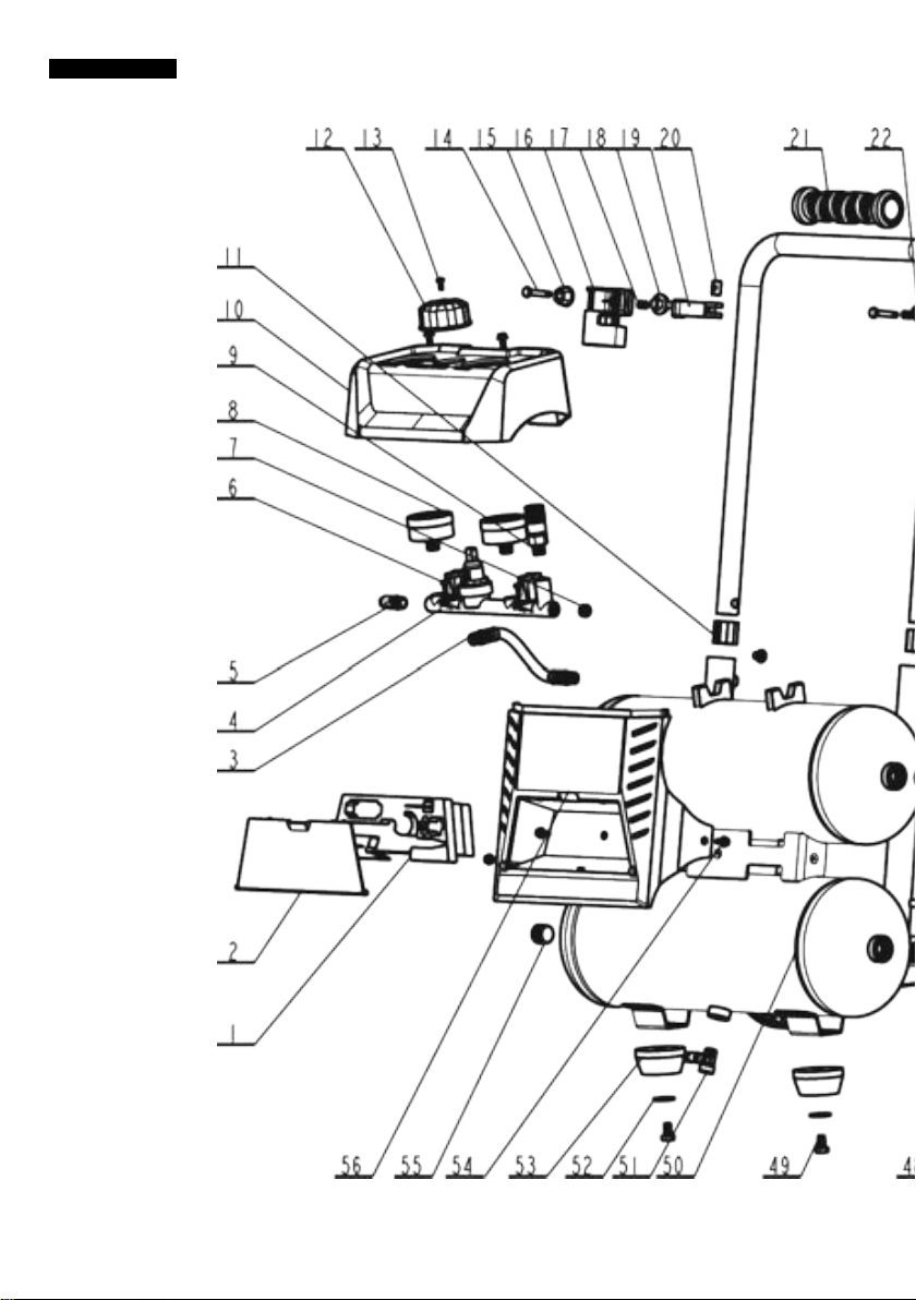
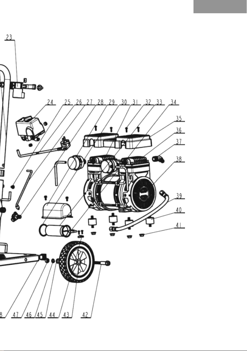
Figures
Please nd the relevant gures referenced in the instructions on page 7.
Table of content
Important safety information ............................................................................................................................. 8
Figures ............................................................................................................................................................... 8
Technical specications .................................................................................................................................... 9
Tool application.................................................................................................................................................. 9
Declaration of conformity .................................................................................................................................. 9
Explanation of symbols.................................................................................................................................... 10
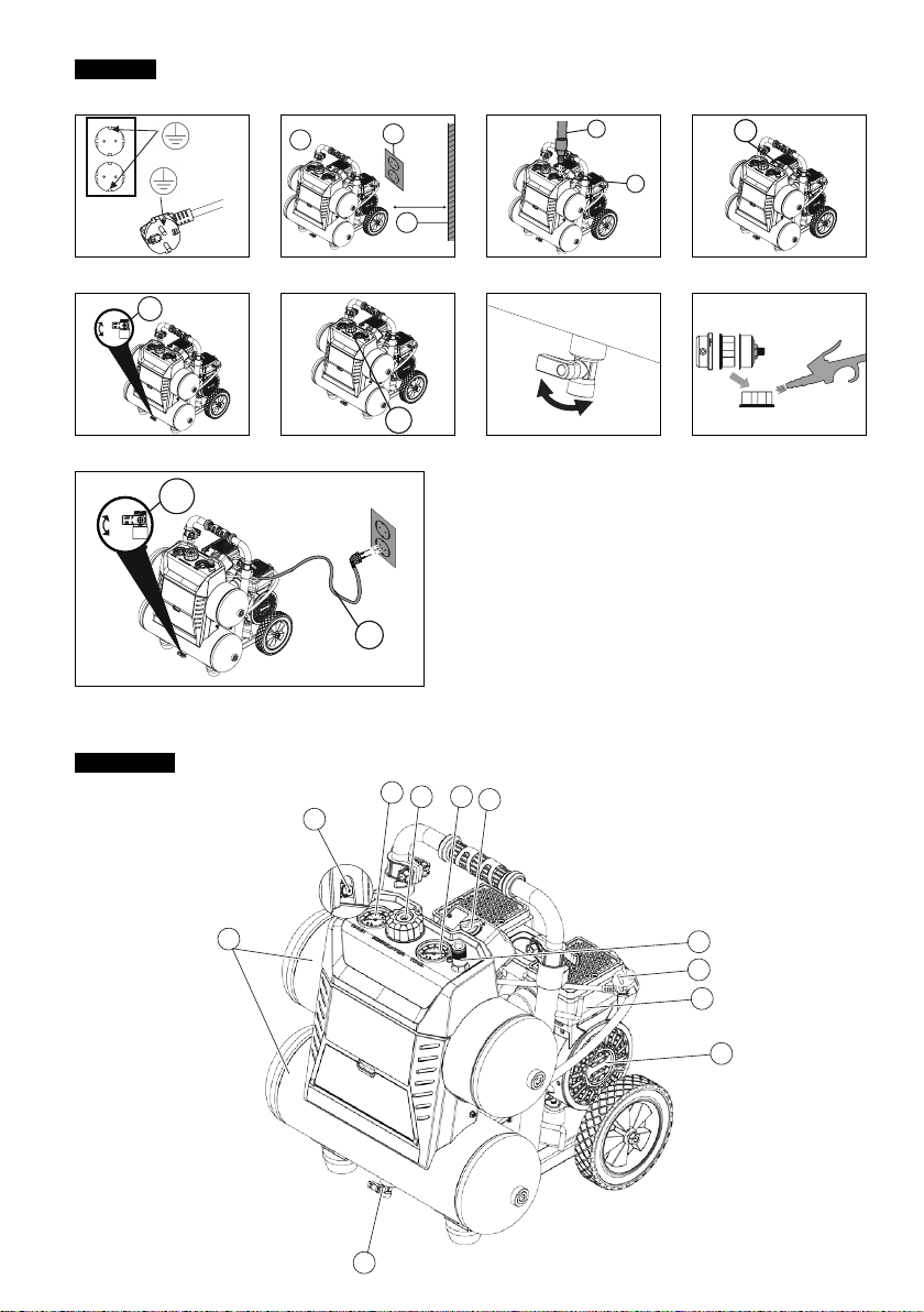
Key parts ...........................................................................................................................................................11
General safety warnings...................................................................................................................................11
Assembly instructions.......................................................................................................................................12
Positioning of the air compressor ................................................................................................................12
Connect air hose to compressor..................................................................................................................12
Operating instructions ......................................................................................................................................12
Break in the pump ........................................................................................................................................12
Before each start-up.....................................................................................................................................12
How to start ..................................................................................................................................................12
How to shut down .........................................................................................................................................12
Maintenance .....................................................................................................................................................13
How to drain tank..........................................................................................................................................13
How to clean the air lter..............................................................................................................................13
Storage .........................................................................................................................................................13
Trouble shooting ...............................................................................................................................................14
TRANSLATION OF THE ORIGINAL INSTRUCTIONS
TJEP 17/15-2
SAFETY AND OPERATION INSTRUCTIONS
MAINTENANCE AND TROUBLE SHOOTING

English
9
Technical specications
Technical info. TJEP 17/15-2
Tank size 17 L
Tank shape Twin
Power 1200 W/1,5 HP
RPM 1400
Rating Amps 5
Working pressure 10.0 bar
Motor type Induction
Oil free/Oil lube Oil-free
Quick coupler 1
Pressure switch 10 Bar
Drain valve Ball valve
Duty cycle 50%
LPA 66 dBA
LWA 80 dBA
As we are constantly developing and improving our products, the information in this overview is subject to change without notice.
Updated information can be found at www.tjep.eu
Tool application
• Pneumatic nailers and staplers
Declaration of conformity
We;
Suzhou Alton Electrical & Mechanical Industry Co., Ltd, N.Linhu Road, E.Laixiu Road, Foho Hi-tech Development Zone, Suzhou 215211,
Jiangsu,China
declare under our sole responsibility that the;
TJEP 17/15-2 compressor
conforms with the directive(s), its amedment(s) and standard(s);
2014/30/EU, 2006/42/EC, 2011/65/EU+(EU)2015/863.
EN 1012-1:2010, EN 60204-1:2018, EN 55014-1:2017, EN 55014-2:2015, EN 61000-3-2:2014, EN 61000-3-3:2013/A1:2019
Notied Body: CEM International Ltd Westmead House, Westmead Farnborough, Hampshire, GU14 7LP UK(1942)
Authorized contact in EU to compile the Technical File;
KGK A/S, Møllevej 9 - H2, DK-2990 Nivå, Tel: +45 45 76 17 00, Mr. Måns Spånberg
Serial number can be found on the front page.
Document ref. No. ZD202009 · Date: 9/30/2020
David Lu
Director, Suzhou Alton Electrical & Mechanical Industry Co., Ltd, Jiangsu,China

10
Explanation of symbols
Symbols in manual
!
The safety alert symbol indicates a potential hazard to personal injury. A signal word (DANGER,
WARNING, or CAUTION) is used with the alert symbol to designate a degree or level of hazard
seriousness. A safety symbol may be used to represent the type of hazard.
The signal word NOTICE is used to address practices not related to personal injury.
DANGER: Indicates a hazard which, if not avoided, will result in death or serious injury.
WARNING: Indicates a hazard which, if not avoided, could result in death or serious injury.
CAUTION: Indicates a hazard which, if not avoided, could result in minor or moderate injury.
Read and understand compressor labels and manual. Failure to follow warnings could result in
serious injury.
Operators and others in work area shall wear impact-resistant eye protection with side shields.
Operators and others in work area shall wear hearing protection.
It is recommended that operator and others in work area wear CE-marked helmet at the job site.
Symbols on compressor
Read and understand compressor
labels and manual. Failure to follow
warnings could result in serious injury.
This compressor is CE-approved
according to applicable standards.
Dispose product according to the
WEEE directive.
The product complies with RoHS
regulations
Tank capacity
RPM Rounds per minute
MAX Maximum pressure
Power consumption
Risk of bursting tank if operating above
maximum operating pressure.
Risk of re. Never operate near am-
mable gasses or vapor.
Risk of accidental start-up in case of a
black-out and subsequent reset. Keep
clear of rotating parts.
Risk of eye injury. Always wear CE-ap-
proved safety glasses when operating
the compressor.
Risk of electrical shock could result in
death or serious injury. Only connect
the compressor to a properly grounded
receptacle.
Risk of high temperatures
Pressure discharge. Keep body parts
and bystanders away
2× 2424 Drain tank min 2 times a day.

English
11
Key parts
Parts description - see drawing on page 7
AAIR COMPRESSOR PUMP: The pump compresses the air and discharges it into the tank via the piston
that moves up and down in the cylinder.
B
ELECTRIC MOTOR: The motor is used to power the pump. It is equipped with a thermal overload
protector. If the motor overheats for any reason, the thermal overload protector will shut it down in order
to prevent the motor from being damaged.
CSAFETY VALVE: This valve is used to prevent the compressor from building too much pressure. If the
pressure reaches the preset level in the tank, it will automatically pop open.
D
PRESSURE SWITCH: This switch turns on the compressor and is operated manually. When in the
ON position, it allows the compressor to start up or shut down automatically, without warning, upon air
demand. ALWAYS set this switch to OFF when the compressor is not being used and before unplugging
the compressor.
E
PRESSURE REGULATOR: The regulator is used to adjust the pressure inside the line to the tool that
is being used. Turn the knob clockwise to increase the pressure and counter-clockwise to decrease the
pressure.
FTANK PRESSURE GAUGE: The gauge measures the pressure level of the air that is stored in the tank.
It cannot be adjusted by the operator and it does not indicate the pressure inside the line.
GOUTLET PRESSURE GAUGE: The gauge measures the regulated outlet pressure.
HQUICK COUPLER: The quick coupler is connected to a quick connector which is connecting to air hose.
IDRAIN VALVE: The drain valve is used to remove moisture from the air tank after the compressor is
shut o.
JAIR TANK: The tank is where the compressed air is stored.
K
POWER CORD: This product is for use on a nominal 230-volt circuit and should be grounded. A cord
with a grounding plug must be used. Make sure that the product is connected to an grounded outlet that
has the same conguration as the plug (see Fig. A). No adapter should be used with this product. Check
with a licensed electrician if the grounding instructions are not understood or there is doubt as to whether
the product is properly grounded. If the plug does not t the outlet, have a proper grounded plug installed
by a licensed electrician.
!DANGER:
Improper installation of the grounding plug will result in
a risk of electric shock. If repair or replacement of the
cord or plug is necessary, do not connect the ground-
ing wire to either at blade terminal. The outer surface
of grounding wire is mixed with yellow and green.
General safety warnings
• Do not operate the compressor until you have
read and understand this instruction manual
for safety, operation and maintenance instructions.
WARNING:
• Risk of re caused by sparks from motor and pres-
sure switch could result in death or serious injury.
• Do not operate compressor near ammable gas
or vapor. Never store ammable liquids or gas in
vicinity of compressor.
• High pressure air could result in death or serious
injury. Shut o unit, unplug and release air pressure
prior to servicing.
• Never operate above maximum operating pressure
of the nailer/stapler.
• Drain water from tank after each use.
• Do not weld or repair tank.
• Do not operate with pressure switch or safety valve
set above maximum allowable working pressure.
• Hot compressors surfaces could result in serious
injury. Allow compressor to cool before touching.
• Using compressor to supply breathing air could
result in death or serious injury.
• Do not spray ammable materials in vicinity of any
ame or ignition sources including the compressor.
• Do not restrict compressor ventilation openings or
place objects against or on top of the compressor
• Operate compressor only in a clean, dry, well
ventilated area.
• Do not operate unattended. Always turn o and
unplug the compressor when not in use.
• Risk of serious eye injury from moisture and
debris. Operators and others in work area
!

12
shall wear CE approved and impact-resistant eye
protection with side shields when working with the
compressor and/or opening the drain valve.
• Do not spray any part of the body.
• Shock risk could result in death or serious injury.
Only connect the compressor to a properly ground-
ed receptacle.
• Dust can be created when cutting, sanding,
drilling or grinding materials such as wood,
paint, metal, concrete, cement, or other
masonry. To reduce your exposure to these
chemicals, work in a well ventilated area and AL-
WAYS wear approved safety equipment.
• KEEP CHILDREN AWAY FROM THE COMPRES-
SOR AT ALL TIMES.
CAUTION:
• High pressure air containing water condensation
could result in minor or moderate injury. Do not
spray at any person.
NOTICE:
• If the pump has been transported or turned upside
down (even partially), allow the pump to sit in a nor-
mal, upright position for approximately 10 minutes
before starting.
Assembly instructions
• Unpack the compressor. Inspect the compressor
for damages. If the compressor has been damaged,
contact your TJEP dealer immediately.
• Check the air compressor’s identication label to ensure
that you have purchased the intended model and that it
has the required pressure rating for its intended use.
• The carton should contain the compressor and
these safety and operation instructions.
Positioning of the air compressor
1. Position the air compressor (1) near an electrical
outlet (2) (Fig. B).
2. The compressor must be at least 31 cm from any
wall (3) or obstruction, in a clean, well-ventilated area
to ensure sucient air ow and cooling (Fig. B).
3. Place the compressor on the oor or a hard, level
surface.The compressor must be level to ensure prop-
er drainage of the moisture in the tank.
Connect air hose to compressor
1. Connect the air hose (1) to the compressor’s quick
coupler (2) (Fig. C).
Operating instructions
Break in the pump
1. Set the pressure switch (1) to the OFF position (Fig. D).
2. Open tank drain valve (1) by turning it counter-clock-
wise to permit the air to escape and prevent air
pressure build-up in the air tank during the break-in
period (Fig. E).
3. Turn the pressure knob (1) clockwise until it stops
(Fig. F).
4. Plug in the power cord
∙Use a dedicated circuit. The compressor will
use the full capacity of a typical 10A household
circuit. If any other electrical devices are drawing
from the compressor’s circuit, the compressor
may fail to start or an overload circuit can result
in sluggish starting that causes the motor over-
load protection system or circuit breaker to trip,
especially in cold conditions.
∙Disconnect the power cord only after break-in
process has been completed, otherwise the
motor might get damaged.
5. Set the pressure switch (1) to the ON position (Fig.
D). The compressor will start. Run the compressor for
30 minutes. If it fails, turn it o immediately and contact
your local TJEP-dealer.
Please note that breaking-in the unit is only required
prior to rst use.
6. After 30 minutes, turn o the pressure switch.
7. Close the tank drain valve (1) by turning it clockwise
(Fig. E).
8. Set the pressure switch to the ON position. (Fig. D)
The air receiver will ll to “cut-out” pressure and then
the compressor’s motor will stop. The compressor is
now ready for use.
Before each start-up
1. Set the pressure switch (1) to the OFF position (Fig.
D).
2. Turn the pressure regulator knob (1) counterclock-
wise until it stops (Fig. F).
3. Attach hose and accessories (Fig. C).
How to start
1. Close the tank drain valve (1) (Fig. I)
2. Plug-in the power cord (2) (Fi. I)
3. Set the pressure switch to the ON position and allow
the tank pressure to build (Fig. D). Motor will stop
when tank pressure reaches cut-out pressure.
4. Turn the air pressure regulator knob clockwise until
desired pressure is reached (Fig. F).
5. The compressor is ready for use.
How to shut down
1. Set the pressure switch (1) to the OFF position
(Fig. D).
2. Unplug the power cord (2) (Fig. I).
3. Set the tank drain valve (1) to ON to ensure the tank
is drained (Fig E).
!

English
13
Maintenance
Item Description / reason Service
interval
Drain the
tank
Through normal operation of your
compressor, condensation of water
will accumulate in the tank. To prevent
corrosion of the tank from the inside,
condensation must be drained twice a
day. Be sure to wear safety glasses.
Relieve the air pressure in the system
then open the drain valve on the bottom
of the tank to drain. Under cold condi-
tions it is especially important to drain
the tank after each use to reduce the
chance of problems resulting from the
freezing of condensation water.
NOTE: Refer to instructions on how to
drain tank.
Twice a
day
Test for
leaks
Check that all connections are tight.
Small leaks in the tank, hoses, connec-
tions or transfer tubes will substantially
reduce the compressor and tool perfor-
mance. Spray a small amount of soapy
water around the area of suspected
leaks with a spray bottle. If bubbles
appear, repair, replace or reseal the
faulty component. Do not over-tighten
any connections.
Monthly
Clean the
air lter
A dirty air lter will reduce compressor
performance and life. To avoid contam-
inating the pump, the lter should be
cleaned frequently and replaced on a
regular basis. Clean the cartridge lter
by blowing on it with a blow gun.
NOTE: Refer to instructions on how to
clean the air lter.
Weekly
How to drain tank
1. Set the pressure switch (1) to the OFF position (Fig.
D).
2. Unplug the power cord (2) (Fig. I).
3. Turn air pressure regulator knob counter-clockwise
to set the outlet pressure to zero (Fig. F)
4. Place suitable container under unit to catch water.
5. Slightly tilt unit and gently turn drain valve coun-
ter-clockwise to open. (Fig. G)
6. After the water has been drained,close the drain
valve (clockwise) (Fig. G). The air compressor can now
be stored.
How to clean the air lter
A dirty lter will reduce the unit s performance and life.
To avoid any contamination inside the pump, the lter
should be cleaned weekly and replaced on a regular
basis. The cartridge lter should be cleaned with blow
gun (Fig. H).
Storage
Before storing the air compressor:
1. Drain tank
2. Use an air blow gun to clean all dust and debris from
the compressor.
3. Disconnect and wind up the power cord.
4. Clean the ventilation openings on the motor enclo-
sure with a damp cloth.
5. Drain all moisture from the tank.
6. Pull the pressure safety valve to release all pressure
from the tank.
WARNING:
• Storage covers could cause a re resulting in death
or serious injury.
• Do not place a storage cover over a hot air com-
pressor.
• Let equipment cool for a sucient time before plac-
ing the cover on the equipment.
• Store the air compressor in a clean and dry loca-
tion.
• In cold weather, store the compressor in a warm
building when it is not in use. This will reduce prob-
lems related to starting the motor and the freezing
of water condensation.
!

14
Trouble shooting
Problem Possible cause Solutions
The motor will not run or start
The power cord is not
plugged in. Plug the power cord into a grounded outlet.
The pressure switch is in the
O (OFF) position. Set the pressure switch to the ON position.
The extension cord is the
wrong wire gauge or is too
long.
Check extension cord information for the proper wire gauge and
cord length.
The motor’s thermal overload
protection has tripped.
Turn the air compressor o, unplug the power cord and wait until the
motor has cooled down. Plug in the power cord only after the motor
has cooled down, and wait at least 5 minutes to make sure the
thermal overload protector has recovered.
A fuse has blown or a circuit
breaker has been tripped.
Replace the fuse or reset the circuit breaker.
Verify that the fuse has the proper amperage.
Check for low voltage conditions.
Disconnect any other electrical appliances from the circuit or oper-
ate the compressor on a dedicated circuit.
The air tank pressure
exceeds the preset pressure
switch limit.
The motor will start automatically when the tank pressure drops
below the cut-in pressure.
The safety valve is stuck
open. Clean or replace the safety valve.
Electrical connections are
lose. Contact your TJEP dealer for repair
The motor, capacitor or safety
valve is defective. Contact your TJEP dealer for repair
The motor runs continuously
when the pressure switch is in
the ON position.
The pressure switch does
not shut o the motor when
the air compressor reaches
the cut-out pressure and the
safety valve activates.
Set the pressure switch to the OFF position. If the motor does
not shut o, unplug the air compressor. If the pressure switch is
defective, replace it.
The compressor’s capacity is
not enough.
Check the air requirements of the accessory that is being used. If it
is higher than the air ow (litre per minute) and pressure supplied by
the compressor, a larger capacity compressor is needed.
The regulator does not
regulate the pressure.
The regulator or its internal
parts are dirty or damaged. Replace the regulator.

English
15
Problem Possible cause Solutions
The pressure is low or there is
not enough air.
There is a leak at one of the
ttings.
Check the ttings with soapy water. Tighten or reseal leaking ttings
(apply plumber s tape on threads). Do not over tighten.
The tank drain valve is open. Close the drain valve.
The air intake is restricted. Clean or replace the air lter elements.
Prolonged excessive use
of air. Decrease the amount of air used.
There is a hole in the air
hose. Check the air hose and replace it if necessary.
The tank leaks. Replace the tank immediately. Do not attempt to repair it.
The valve is leaking. Check for worn parts and replace them if necessary.
There is moisture in the
discharge air.
There is condensation in the
air tank caused by a high
level of atmospheric humidity
or because the compressor
has not been running long
enough.
Drain the air tank. Drain the air tank more often in humid weather
and use an air-line lter.
The compressor overheats.
The ventilation is inadequate. Relocate the compressor to an area with cool, dry and well-circu-
lated air.
Cooling surfaces are dirty. Clean all cooling surfaces on the pump and the motor thoroughly.
The valve is leaking. Replace worn parts and reassemble using new plumber’s tape.
For failure other than above situations, please stop using the compressor and contact your local TJEP dealer for service.

16
ИЗПОЛЗВАНЕТО НА КОМПРЕСОРА ПО НЕПРАВИЛЕН ИЛИ ОПАСЕН НАЧИН МОЖЕ ДА
ДОВЕДЕ ДО СМЪРТ ИЛИ СЕРИОЗНО НАРАНЯВАНЕ. МНОГО Е ВАЖНО ПОТРЕБИТЕ-
ЛЯТ, КОЙТО ЩЕ ИЗПОЛЗВА КОМПРЕСОРА, ДА ПРОЧЕТЕ И РАЗБЕРЕ ТОВА РЪКОВОД-
СТВО, ПРЕДИ ДА ЗАПОЧНЕ РАБОТА С КОМПРЕСОРА. АКО ДРУГИ ХОРА ЗАПОЧВАТ ДА
ИЗПОЛЗВАТ КОМПРЕСОРА, ОСИГУРЕТЕ ИМ ДОСТЪП ДО РЪКОВОДСТВОТО ПРЕДИ
ТОВА.
Пазете това ръководство на безопасно място за бъдеща справка.
Важна информация за безопасност
Производителят не може по никакъв начин да предвиди всички възможни случаи, които може да
включват опасност. Следователно предупрежденията в това ръководство, както и етикетите и марки-
ровките, прикрепени към компресора, не са изчерпателни. Ако използвате процедура, работен метод
или оперативна техника, която производителят не препоръчва специално, трябва да се уверите, че това
е безопасно за вас и другите. Трябва също така да гарантирате, че процедурата, работният метод или
оперативната техника, която избирате, не предизвиква небезопасна работа на компресора.
Изображения
Намерете съответните фигури, споменати в инструкциите на страница 7.
Съдържание
Важна информация за безопасност ........................................................................................................... 16
Изображения.................................................................................................................................................. 16
Технически спецификации............................................................................................................................17
Приложение на инструменти ........................................................................................................................17
Декларация за съответствие........................................................................................................................17
Описание на символите ................................................................................................................................18
Ключови части ................................................................................................................................................19
Общи предупреждения за безопасност......................................................................................................19
Монтажни инструкции................................................................................................................................... 20
Позициониране на въздушния компресор ............................................................................................ 20
Свържете маркуча за въздух към компресора..................................................................................... 20
Инструкции за работа ................................................................................................................................... 20
Пускане в експлоатация на помпата...................................................................................................... 20
Преди всяко стартиране .......................................................................................................................... 21
Начин на стартиране ................................................................................................................................ 21
Как се изключва......................................................................................................................................... 21
Поддръжка...................................................................................................................................................... 21
Начин на дрениране на резервоара....................................................................................................... 21
Начин на почистване на въздушния филтър........................................................................................ 22
Съхранение................................................................................................................................................ 22
Отстраняване на неизправности ................................................................................................................ 23
ПРЕВОД НА ОРИГИНАЛНИТЕ ИНСТРУКЦИИ
TJEP 17/15-2
ИНСТРУКЦИИ ЗА БЕЗОПАСНОСТ И РАБОТА
ПОДДРЪЖКА И ОТСТРАНЯВАНЕ НА НЕИЗПРАВНОСТИ

Български
17
Технически спецификации
Техническа информация TJEP 17/15-2
Размер на резервоара 17 L
Форма на резервоара Двоична
Захранване 1200 W/1,5HP
RPM 1400
Номинални ампери 5
Работно налягане 10,0 bar
Тип мотор Индукционен
Безмаслен/Смазочно масло Безмаслен
Бързосменен адаптер 1
Превключвател за налягане 10 bar
Дренажен клапан Сферичен кран
Режим на работа 50%
LPA 66 dBA
LWA 80 dBA
Тъй като непрекъснато развиваме и подобряваме нашите продукти, информацията в този общ преглед подлежи на
промени без уведомление за това. Актуализираната информация може да се намери на www.tjep.eu
Приложение на инструменти
• Пневматични такери и телбоди
Декларация за съответствие
Ние;
Suzhou Alton Electrical & Mechanical Industry Co., Ltd, N.Linhu Road, E.Laixiu Road, Foho Hi-tech Development Zone, Suzhou 215211,
Дзянсу, Китай
декларираме на своя еднолична отговорност, че;
компресорът TJEP 17/15-2
съответства на директивите, техните изменения и стандарти;
2014/30/EU, 2006/42/EC, 2011/65/EU+(EU)2015/863.
EN 1012-1:2010, EN 60204-1:2018, EN 55014-1:2017, EN 55014-2:2015, EN 61000-3-2:2014, EN 61000-3-3:2013/A1:2019
Нотифициран орган: CEM International Ltd Westmead House, Westmead Farnborough, Хемпшир, GU14 7LP Обединеното кралство
(1942)
Упълномощен контакт в ЕС за окомплектоване на Техническата информация;
KGK A/S, Møllevej 9 - H2, DK-2990 Nivå, Тел.: +45 45 76 17 00, г-н Måns Spånberg
Серийният номер може да се намери на заглавната страница.
Референтен номер на документа ZD202009 · Дата: 30.9.2020 г.
David Lu
директор, Suzhou Alton Electrical & Mechanical Industry Co., Ltd, Jiangsu, Китай

18
Описание на символите
Символи в ръководството
!
Предупреждаващият символ за безопасност указва потенциална опасност от нараня-
ване. Сигнална дума (ОПАСНОСТ, ПРЕДУПРЕЖДЕНИЕ или ВНИМАНИЕ) се използва с
предупреждаващия символ, за да обозначи степен или ниво за сериозност на опасността.
Символът за безопасност може да се използва за представяне на типа опасност.
Сигналната дума БЕЛЕЖКА се използва за насочване към практики, които не са свързани
с телесна повреда.
ОПАСНОСТ: Указва опасност, която, ако не бъде избегната, ще причини смърт или сериоз-
на телесна повреда.
ПРЕДУПРЕЖДЕНИЕ: Указва опасност, която, ако не бъде избегната, може да причини
смърт или сериозна телесна повреда.
ВНИМАНИЕ: Указва опасност, която, ако не бъде избегната, може да причини лека или
средна телесна повреда.
Прочетете и разберете ръководството и етикетите на компресора. Несъблюдаването на
предупрежденията може да доведе до сериозно нараняване.
Операторите и другите лица в работната област трябва да носят устойчиво на удари обо-
рудване за защита на очите със странични щитове.
Операторите и другите лица в работната област трябва да носят защита за слуха.
Препоръчва се операторът и другите лица в работната област да носят маркиран по CE
шлем на работния обект.
Символи на компресора
Прочетете и разберете ръковод-
ството и етикетите на компресора.
Несъблюдаването на предупрежде-
нията може да доведе до сериозно
нараняване.
Този компресор е одобрен по CE
съгласно приложимите стандарти.
Изхвърляйте продукта съгласно из-
искванията на директивата относно
ОЕЕО.
Продуктът спазва изискванията на
директивата относно RoHS
Капацитет на резервоара
RPM Обороти в минута
MAX Максимално налягане
Консумация на енергия
Риск от избухване на резервоара,
ако функционира над максималното
работно налягане.
Риск от пожар. Никога не използ-
вайте до запалими газове или
изпарения.
Риск от случайно стартиране в
случай на загасване и последващо
нулиране. Пазете се от въртящите
части.
Риск от увреждане на очите. Винаги
носете одобрени по CE очила за
безопасност, когато работите с
компресора.
Риск от токов удар може да доведе
до смърт или сериозна телесна по-
вреда. Свързвайте компресора само
към правилно заземен приемник.
Риск от високи температури
Освобождаване на налягането. Па-
зете частите на тялото и странични-
те наблюдатели
2× 2424
Дренирайте резервоара
минимум 2 пъти на ден.

Български
19
Ключови части
Описание на частите – вижте схемата на страница 7
АПОМПА НА ВЪЗДУШНИЯ КОМПРЕСОР: Помпата компресира въздуха и го освобождава в
резервоара чрез буталото, което се движи нагоре и надолу в цилиндъра.
В
ЕЛЕКТРИЧЕСКИ МОТОР: Моторът се използва за захранване на помпата. Той е оборудван с
протектор от прегряване. Ако моторът прегрее поради каквато и да е причина, протекторът от
прегряване ще го изключи, за да предпази мотора от увреда.
С
ПРЕДПАЗЕН ВЕНТИЛ: Този вентил се използва за предпазване на компресора от изграждане
на прекомерно налягане. Ако налягането достигне предварително зададеното ниво на резерво-
ара, той автоматично ще се отвори.
D
ПРЕВКЛЮЧВАТЕЛ ЗА НАЛЯГАНЕ: Превключвателят включва компресора и се управлява
ръчно. Когато е в позицията ВКЛЮЧЕНА, това ще позволи на компресора да се стартира или
изключи автоматично, без предупреждение, при необходимост от въздух. ВИНАГИ задавайте
този превключвател на ИЗКЛЮЧЕНА позиция, когато компресорът не се използва и преди да се
изключи компресорът от мрежата.
E
РЕГУЛАТОР НА НАЛЯГАНЕТО: Регулаторът се използва за регулиране на налягането вътре
в линията към инструмента, който се използва. Завъртете копчето по посока на часовниковата
стрелка, за да увеличите налягането, и обратно на часовниковата стрелка, за да го намалите.
F
МАНОМЕТЪР НА НАЛЯГАНЕТО НА РЕЗЕРВОАРА: Манометърът измерва нивото на наляга-
нето на въздуха, който се съхранява в резервоара. Той не може да се регулира от оператора и
не указва налягането вътре в линията.
GМАНОМЕТЪР НА ИЗХОДЯЩОТО НАЛЯГАНЕ: Манометърът измерва регулираното изходно
налягане.
HБЪРЗОСМЕНЕН АДАПТЕР: Бързосменният адаптер е свързан към бърз конектор, който е
свързан към маркуча за въздух.
IДРЕНАЖЕН КЛАПАН: Дренажният клапан се използва за премахване на влагата от въздушния
резервоар след изключване на компресора.
JВЪЗДУШЕН РЕЗЕРВОАР: Резервоарът е там, където се съхранява сгъстеният въздух.
K
ЗАХРАНВАЩ КАБЕЛ: Този продукт е предназначен за употреба с номинална 230-волтова
верига и трябва да се заземи. Трябва да се използва кабел със заземяващ щепсел. Уверете
се, че продуктът е свързан към заземен контакт, който има същата конфигурация като щепсела
(вижте фиг. A). Не трябва да се използва адаптер с този продукт. Консултирайте се с лицензиран
електротехник, ако инструкциите за заземяване не са ви ясни или ако имате съмнение дали
продуктът е правилно заземен. Ако щепселът не пасва на контакта, лицензиран електротехник
трябва да ви инсталира правилно заземен контакт.
!ОПАСНОСТ:
Неправилното инсталиране на заземяващия
щепсел може до доведе до риск от електрически
удар. Ако е необходима поправка или подмяна
на кабела или щепсела, не свързвайте заземя-
ващия проводник в нито един от плоските клеми.
Външната повърхност на заземяващия проводник
е смесена с жълто и зелено.
Общи предупреждения за безопасност
• Не работете с компресора, докато не про-
четете и не разберете това ръководство
с инструкции за инструкциите за безопасност,
работа и поддръжка.
!ПРЕДУПРЕЖДЕНИЕ:
• Риск от пожар, причинен от искри от мотора и
превключвателя за налягането, може да дове-
де до смърт и сериозна телесна повреда.
• Никога не работете с компресора до запалими газо-
ве или изпарения. Никога не съхранявайте запали-
ми течности или газове в близост до компресора.
• Въздухът под високо налягане може да доведе
до смърт или сериозна телесна повреда.
Изключете уреда, разкачете го от мрежата и
освободете въздушното налягане преди серви-
зно обслужване.
• Никога не работете над максималното работно
налягане на такера/телбода.
• Дренирайте водата от резервоара след всяка
употреба.

20
• Не заварявайте и не поправяйте резервоара.
• Не използвайте превключвателя за налягане
или предпазния вентил, когато са зададени над
максимално допустимото работно налягане.
• Горещите повърхности на компресора може да
причинят сериозна телесна повреда. Оставете
компресора да се охлади, преди да го докоснете.
• Използването на компресора за доставяне на
въздух за дишане може да доведе до смърт или
сериозна телесна повреда.
• Не пръскайте запалими материали в близост
до каквито и да е източници на пламъци или
запалване, включително до компресора.
• Не ограничавайте вентилационните отвори на
компресора и не поставяйте предмети около
или върху компресора
• Използвайте компресора само в чисти, сухи и
добре проветрени пространства.
• Не използвайте без надзор. Винаги изключвай-
те и разкачвайте от мрежата компресора, когато
не се използва.
• Риск от сериозно нараняване на очите
от влагата и отпадъците. Операторите
и другите лица в работната област трябва да
носят одобрено по CE и устойчиво на удари
оборудване за защита на очите със странични
щитове, когато работят с компресора и/или
отварят дренажния клапан.
• Не пръскайте върху никаква част от тялото.
• Рискът от удар може да доведе до смърт или
сериозна телесна повреда. Свързвайте компресо-
ра само към правилно заземен приемник.
• Прахът може да се създаде при рязане,
шлифоване, пробиване или стъргане на
материали, като например дърво, боя,
метал, бетон, цимент или други зидарии.
За да се намали излагането на тези химикали,
работете в добре проветрена зона и ВИНАГИ
носете одобрено предпазно оборудване.
• ДРЪЖТЕ ДЕЦАТА ДАЛЕЧ ОТ КОМПРЕСОРА ПО
ВСЯКО ВРЕМЕ.
!ВНИМАНИЕ:
• Въздухът под високо налягане, съдържащ кон-
дензация на вода, може да доведе до леки или
средни телесни повреди. Не пръскайте върху
други лица.
БЕЛЕЖКА:
• Ако помпата е била транспортирана или обър-
ната обратно (дори частично), оставете я да
постои в нормална изправена позиция за около
10 минути, преди да стартирате.
Монтажни инструкции
• Разопаковайте компресора. Инспектирайте
компресора за повреди. Ако компресорът е ув-
реден, се свържете със своя търговец на TJEP
незабавно.
• Проверете идентификационния етикет на
въздушния компресор, за да се уверите, че сте
закупили правилния за целта модел и че той има
необходимата номинална стойност на налягане за
предназначението.
• Кашонът трябва да съдържа компресора и на-
стоящите инструкции за безопасност и работа.
Позициониране на въздушния компресор
1. Позиционирайте въздушния компресор (1) в
близост до електрическа розетка (2) (фиг. B).
2. Компресорът трябва да е поне на 31 cm от стена
(3) или други обструкции, в чиста и добре прове-
трена зона, за да се гарантират достатъчен поток
на въздух и охлаждане (фиг. B).
3. Поставете компресора на пода за твърда и
изравнена повърхност. Компресорът трябва да е
нивелиран, за да се гарантира правилното дрени-
ране на влагата в резервоара.
Свържете маркуча за въздух към ком-
пресора.
1. Свържете маркуча за въздух (1) към бързосмен-
ния адаптер на компресора (2) (фиг. C).
Инструкции за работа
Пускане в експлоатация на помпата
1. Задайте превключвателя за налягане (1) на ИЗ-
КЛЮЧЕНА позиция (фиг. D).
2. Отворете дренажния клапан на резервоара
(1), като го завъртите обратно на часовниковата
стрелка, за да позволите на въздуха да избяга
и да предотвратите изграждането на въздушно
налягане във въздушния резервоар по време на
периода на пускане в експлоатация (фиг. E).
3. Завъртете копчето за налягането (1) по посока
на часовниковата стрелка, докато спре (фиг. F).
4. Включете захранващия кабел
∙ Използвайте специална верига. Компресорът
ще използва пълния капацитет от типична
верига за домакинството от 10A. Ако някое
друго електрическо устройства черпи от ве-
ригата на компресора, компресорът може да
откаже да се стартира или претоварването на
веригата може да доведе до бавно стартира-
не, което причинява блокиране на защитната
система от претоварване на мотора или
прекъсвача на веригата, особено при студени
условия.
∙ Изключете захранващия кабел само след
като процесът на пускане в експлоатация е
завършен, иначе моторът може да се увреди.
5. Задайте превключвателя за налягане (1) на
ВКЛЮЧЕНА позиция (фиг. D). Компресорът ще
стартира. Оставете компресора да работи 30 ми-
нути. Ако това не се случи, изключете го незабав-
но и се свържете с местния търговец на TJEP.
Обърнете внимание, че пускането в експлоата-
ция се изисква само преди първото използване.
Table of contents
Languages:
Other Kyocera Air Compressor manuals
Popular Air Compressor manuals by other brands

Campbell Hausfeld
Campbell Hausfeld Oil Lubricated Portable Air Compressors operating instructions

HELIX
HELIX 8200 Operating and service instructions

Michelin
Michelin MB Instruction manual and safety instructions

Silverline
Silverline 234578 manual

Frascold
Frascold R-TSH Series Installation and start-up instruction

Airpress
Airpress LMO 50-270 user manual

Danfoss
Danfoss PSH Series instructions

Z.I.P.P.ER MASCHINEN
Z.I.P.P.ER MASCHINEN ZI-COM50-10 user manual

Black Ridge
Black Ridge BR3000 instruction manual

Central Pneumatic
Central Pneumatic 39750 Assembly and operating instructions

pilotair
pilotair K25-Vi Instructions and parts list

C-Aire
C-Aire S33 owner's manual