Kyocera AJP-1100 Operation manual

69801122-00 STD
01-22
AJP-1100

1
1
127
8
9
11
12
13
14
34
10
56
15
2
15
4
24
3
23
56
7 8 9
9
10
10
5
2 3
6
4
78

2
9 10 11
13
12 14
171615
19
18
A
B
17
16
B
A
13
16
20
18
12
16
13
19
9
10
27
10
26
12
25
29
30
31
30
31
29
28

3
20 21 22
24
23 25
28
27
26
31 32
30
29
14
7
22
12
25
9
11
7
21
25
tighten
loosen
29
34
32
33
35
30
tighten
loosen
29
36
tighten
loosen 31
30 30
31
30
31
37
tighten
33
32
34
32
37

4
Preparation
Before starting up your machine, we advise you to carefully
read through this instruction manual. Follow all instructions
to minimize the risk of injuries when using the machine.
Prior to operation
Before starting up your machine, please check it carefully
for any defects. If you nd any, do not start up your machine
and contact your distributor.
Especially check:
The insulation of the electric cable should be faultless
and without any cracks. If the electric cable is damaged, it
should be replaced by our authorized distributor.
Mains power supply connection
The following should be observed when connecting the
machine to the electric installation:
• Check before operation that the local power supply is
the same as the specications on the rating label.
• This machine is equipped with universal motor with
double insulation. It is not necessary to have earth
connection.
• The electric installation shall be made by a certified
electrician.
• It is strongly recommended that the power supply to the
machine should include a residual current device (RCD).
• Product protection degree:IPX5
General safety regulations and accident
prevention
It is essential that you read the safety regulations and
operating instructions in their entirety and follow the
information contained therein in order to eliminate the
possibility of an accident or potentially dangerous situation
from occurring while working with the machine.
• The power plug must be plugged into a properly installed
socket. The power supply should include a residual
current device for max. 30 mA.
• Always check the device, the mains cable and the plug
before using the machine. Only operate the device when
it is in good working order and has not been damaged in
any way. Damaged parts must be immediately replaced
by a qualied electrician.
• Always pull the power plug out of the socket outlet before
doing any work on the machine, before changing the
nozzle and whenever it is not being used.
• Warning! Inadequate extension cords can be dangerous.
• If an extension cord is used, it shall be suitable for
outdoor use, and the connection has to be kept dry.
• Only use suitable extension cable when working
outdoors. Extension cable must have a minimum cross-
section of 1.5 mm2.
• Warning! This device was developed to be used with
cleaning agents supplied or recommended by the
manufacturer. The use of any other cleaning agents or
chemicals can negatively aect the safety of the device.
• Cable connections should be kept dry and off the
ground. Always uncoil the extension cable completely to
avoid heat damage to the cable.
• Warning! Do not use the device when other persons or
animals are in the near vicinity unless they are wearing
appropriate protective clothing.
Name of Parts:
1. Main unit
2. Handle
3. Spray gun holder
4. Cord hook
5. Wheel
6. Wheel cover
7. Variable nozzle lance
8. Mid nozzle lance
9. Spray gun
10. Spray gun hose
11. Foam nozzle
12. Water connector
13. Hose joint
14. Nozzle cleaning pin
15. Screw
16. Water supply hose (option)
17. Hose clamp (option)
18. Main switch
19. Safety lock button
20. Trigger
Carefully read and understand these instructions
before operating this high pressure washer.
Package Contents (Fig.1)
1. Main unit
2. Handle
3. Spray gun holder
4. Cord hook
5. Wheel
6. Wheel cover
7. Variable nozzle lance
8. Mid nozzle lance
9. Spray gun
10. Spray gun hose (5m)
11. Foam nozzle
12. Water connector
13. Hose joint
14. Nozzle cleaning pin
15. Screw
Technical data
Power rating input 1,400 W
Rated pressure 70 bar (7 MPa)
Allowable pressure 100 bar (10 MPa)
Rated ow 5.5 L / min
Max. inlet water pressure 0.7 MPa
Max. temperature: 40°C
Adding water From a faucet
Weight 4.5 Kg
Sound pressure level
Uncertainty
LpA=77dB(A)
KPA=3dB
Sound power level LwA=92dB(A)
Vibration Value aH=1.8m/s2
Kah=0.05m/s2
21. Power cord
22. Filter
23. Hook
24. Hook
25. Water inlet
26. Release button
27. Release button
28. Self-priming kit (option)
29. Self-priming lter (option)
30. Self-priming hose (option)
31. Strainer (option)
32. Filter cap (option)
33. Filter (option)
34. Rubber seal (option)
35. Rubber seal
36. Ring (option)
37. Filter case (option)

5
• Warning! High pressure jets can be dangerous when the
machine is not use properly. Do not direct the jet toward
persons, animals, live electrical equipment or the device
itself.
• Do not direct the jet against yourself or others in order to
clean clothes and footwear.
• Children should be supervised to ensure that they do not
play with the machine.
• This machine is not intended for use by persons (includ-
ing children) with reduced physical, sensory or mental
capabilities, or lack of experience and knowledge, “High
pressure cleaners shall not be used by children or un-
trained personnel.”
• Warning! Spray gun hoses, fittings and couplings are
important components for the safety of the device. Only
use spray gun hoses, ttings and couplings that are rec-
ommended by the manufacturer.
• In order to ensure the operational safety of the device,
only use genuine manufacturer’s replacement parts or
parts that have been approved by the manufacturer.
• Do not operate the device if the mains cable or other
important parts of device – e.g. safety related elements,
spray gun hose, spray gun – are damaged.
• Do not pull or carry the electric tool by its mains cable.
Protect the mains cable from becoming damaged by oil,
solvents and sharp edges.
• Keep your place of work tidy.
• Ensure that the switch is turned o when connecting the
machine to the power supply.
• Wear the suitable work clothes.
• Check your machine to ensure that it is in good working
order. If it is not functioning properly, have it checked
by our authorized distributor. Have all maintenance and
inspection work carried out only by our authorized dis-
tributor.
• The water jet discharged from the nozzle lance produces
a ‘kickback’ on the spray gun. Therefore, make sure that
you have a solid footing and that you have a rm hold of
the handle grip. In order to protect yourself from possible
ying objects (that are released due to the high pressure).
• The high pressure jet can damage vehicle tyres and tyre
parts. Keep a distance of at least 30 cm from the object
being cleaned.
• If there is a power failure while you are using the machine,
be sure to switch o the machine for safety reasons.
• The electric pump always must be able to draw on a
sucient supply of water. Dry operation causes severe
damage to the seals.
• Disconnect from the power supply before carrying out
user maintenance.
• Only use genuine spare parts from the manufacturer or
approved by the manufacturer.
• If the supply cord is damaged, it must be replaced by our
authorized distributor in order to avoid a hazard.
• Never use the machine in an environment where there
could be a danger of explosion. If any doubt arises,
please contact our authorized distributor.
• It is not allowed to clean asbestos-containing surfaces
with high pressure.
• This machine must not be used at temperatures below
0°C.
• The electric supply connection (for example, connection
the RCD or x wiring) shall be made by a qualied elec-
trician and comply with IEC60364-1: Low-voltage electri-
cal installations.
Safety devices
Safety lock on spray gun
The spray gun features safety lock button (19). When the
lock is activated, the spray gun cannot be operated.
Motor pump protection
The motor is equipped with a motor circuit breaker switch.
When the motor starts to run hot, it is cut out automatically
by this switch. Switch o the machine. Wait 5 ~ 10 minutes
before using the device again. Try to determine the cause
of the fault. If the problem repeats itself, please contact our
service centre.
Operating instructions
Purpose
The machine is designed to clean vehicles, machines,
buildings, facades, etc. in the private sector.
Areas of application
• Never use the machine in potentially explosive areas
under any circumstances!
• The operating temperature must be between 0°C and
+40°C.
• The machine consists of an assembly with a pump,
which is encased in a shock absorbing housing. For
an optimal working position the machine comes with
a lance and a non-slip handle grip, whose shape and
conguration comply with the applicable regulations.
• Do not cover or modify the lance or the spray nozzles in
any way.
• The machine is designed to be used with cold or
lukewarm (max. 40°C); higher temperatures can damage
the pump.
• Do not use water that is dirty, gritty or contains any
chemical products, as these could impair operation and
shorten the life of the machine.
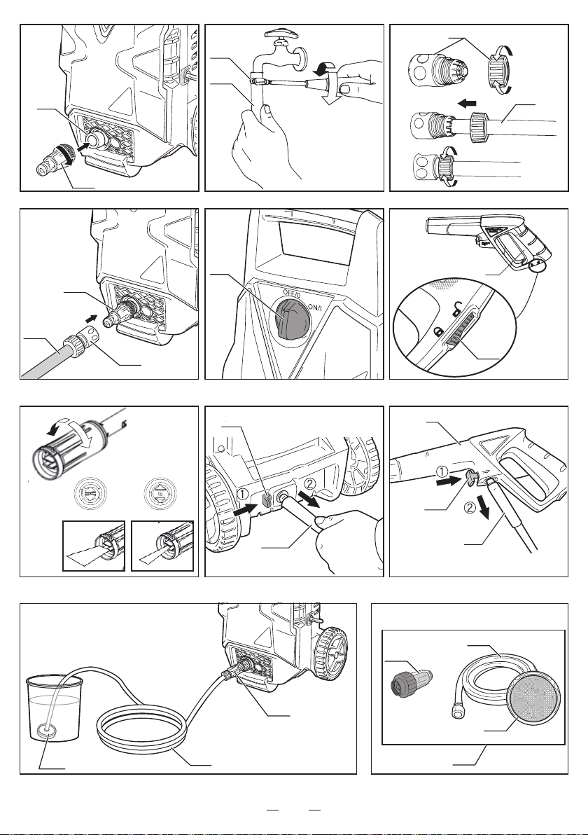
Assembly
*Tools needed for assembly: Water supply hose, Hose
clamp, Phillips screwdriver.
*The water supply hose must have an internal diameter of
at least 13mm (1/2 in.) and must be reinforced. The water
supply must be at least equal to the washer delivery
capacity.
1. Screw the handle (2). (Fig.2)
2. Fit the cord hook (4) into the hook (24). Power cord can
be hung. (Fig. 3)
3. Fit the spray gun holder (3) into the hook (23). Spray
gun (9) can be stored. (Fig. 4)
4. Connect the wheel (5) and wheel cover (6) to the unit.
(Fig.5)
5. Connecting the nozzle lance to the spray gun. (Fig.6)
Fit the nozzle lance (7 and 8) into the spray gun (9) and
rotating it until the two parts are completely locked.
Test the connection by pulling on the nozzle.
6. Connect the spray gun hose (10) to the spray gun (9).
(Fig.7)
WARNING! Water leakage may occur if the hose is not
secured properly or if the connectors are not free from
dirt and debris prior to connecting.

6
7. Connecting the spray gun hose to the water discharge
nozzle. (Fig. 8)
Secure the spray gun hose (10) directly onto the water
discharge nozzle.
WARNING! Jiggling the spray gun hose to the right or
left when connecting, may cause water to leak from the
connection area.
8. Screw the water connector (12) onto the water inlet (25).
(Fig. 9)
9. Attach the water supply hose (16) to the faucet (Fig.
10)
WARNING! Remove dirt and debris from the faucet
and from the outside and inside of the hose.
Allow the water from the faucet to run for a short time
before attaching the hose.
Dirt or debris entering the unit may cause damage to
the pump.
WARNING! Be sure to use water directly from the
water faucet. Hot water (over 40°C) and water from hot
springs may damage the unit.
Attach the water supply hose (16) to the water faucet
with the hose clamp (17).
Tighten the clamp screw to secure the hose to the
faucet.
10. Attaching the hose joint to the water supply hose
(Fig.11)
Loosen and remove the hose link from the hose joint
(13).
Insert the water supply hose (16) through the hose link.
Insert the end of the water supply hose securely into
the connecting portion of the hose joint.
Securely tighten the hose link onto the hose joint by
turning the hose link clockwise.
WARNING! There is a valve attached to the hose joint.
Water will not ow out of the hose until it is attached to
the water connector.
11. Connecting the hose joint to the water connector
(Fig.12)
Push the hose joint (13) onto the water connector (12)
until you hear a 'click' sound.
WARNING! Jiggling the water supply hose to the right
or left when attaching may cause water to leak from
the connection area.
Operating the Switch (Fig.13)
Turning the main switch (18) clockwise to the "ON" position
starts the unit. Returning the switch to the "OFF" position
cuts electrical power to the unit.
Using the Spray gun (Fig.14)
Pulling the spray gun trigger (20) releases a highly
pressurized water ow. Releasing the trigger stops the ow.
The spray gun safety lock button (19) prevents accidental
operation.
When locked, the trigger cannot be depressed.
Nozzle Lance (Fig. 15)
Changing the spray diusion (narrow ⇔wide)
Change the spray diffusion by turning the end of the
variable nozzle lance clockwise for narrow spray diusion
and counterclockwise for wide spray diusion.
Narrow spray … Water is sprayed in a concentrated direct
flow. The narrow spray setting is useful
for removing stubborn grime.
Wide Spray …… Water is sprayed in a widely diffused
ow. The wide spray setting is useful for
removing dirt from large areas, washing
cars, etc.
Operating the Unit
1. Ensure that the main switch (18) is in the OFF position.
Plug in the power cord.
2. Turn on the water faucet to the full on position.
3. Release the spray gun safety lock button (19).
4. Water is sprayed from the nozzle when the spray gun
trigger is depressed.
Before turning the main switch to the ON position,
release all accumulated air from inside the hose and
pump by depressing the trigger.
WARNING! Failure to remove the accumulated air from
the hose and pump before turning on the main switch
may result in decreased pressure and/or damage to the
pump and motor.
5. Turn the main switch to the ON position after water
begins to flow smoothly from the nozzle while
depressing the spray gun trigger.
6. Operate the spray by depressing the spray gun trigger.
The motor stops when the spray gun trigger is released.
When the trigger is depressed, the motor resumes and
pressurized spray is ejected from the nozzle.
WARNING!
• Operate carefully over rough surfaces such as gravel,
broken concrete, or crushed stone.
• Avoid excessive friction that could damage the spray
gun hose when moving around objects such as fences,
blocks, or bricks.
• Ensure that the spray gun hose is straight and free of
any kinks or twists before using.
• During initial use, the spray stream may be intermittent
and erratic while air is being dispelled from within the
pump and hose. When this occurs, continue to depress
the trigger until the spray stream stabilizes.
• Be sure to turn the main switch to the OFF position
when leaving the unit unattended.
• When spraying, ensure that the spray gun trigger is
always depressed and released for intervals lasting
longer than 2 seconds in duration.
Malfunction of the pressure switch may occur from
spray intervals lasting less than 2 seconds.

7
After Use
1. Turn the main switch to the OFF position.
2. Turn the water faucet o.
3. Depress the spray gun trigger until all water has
stopped owing from the nozzle.
4. Pull the hose joint coupler forward to release the water
supply hose from the water connector.
5. Depress the spray gun safety lock button to lock the
trigger.
6. Press the release button (26) to remove the spray gun
hose (10) from the main unit. (Fig. 16)
7. Remove remaining water from the main unit
Turn the main switch to the ON position for 1-2 seconds
to discharge excess water from the spray gun hose
connection port.
WARNING! Exercise caution as the released of excess
water is highly pressurized
WARNING! Leaving the main switch on for longer than
2 seconds may damage the unit. Be sure to turn the
main switch o immediately.
8. Unplug the power cord.
9. Remove the water supply hose from the faucet.
10. Press the release button (27) to remove the spray gun
hose (10) from the spray gun (9). (Fig. 17)
WARNING!
Remove all excess water from the main unit, spray gun
hose, spray gun and nozzles especially in cold weather.
Storing the unit in cold temperatures without removing all
excess water may damage the unit and cause malfunction.
Self-priming kit (optional accessory)
Use with alternative water sources (Fig.18)
By attaching self-priming kit, which is an optional
accessory, this machine can draw in water from
alternative water sources, such as water butts and
water containers.
*
Need to prime the hose beforehand to remove the air
bubble inside the hose.
*
The discharge pressure will be lower compared with
when supplying water from a faucet.
note: Make sure to operate this machine on level ground.
Things to prepare
• Self-priming kit (Fig.19)
• Water for priming the hose (approximately 1L)
• Water container
• Water for cleaning
How to use
WARNING! Make sure to clean the Self-priming
filter, the strainer on Self-priming hose, and filter
on the machine, before connecting. It will cause low
discharge pressure or malfunction of the machine
when using with the dust adhered.
1. Remove spray gun hose from the machine.
• Press the release button (26) to remove the spray gun
hose (10) from the main unit. (Fig. 16)
2.AttachSelf-priminglter.(Fig.20)
*
Remove water supply hose(16) and water connector
(12) if they are set.
• Attach Self-priming lter (29) into water inlet by turning
clockwise.
note:
• Tighten Self-priming lter straight onto the water inlet
by turning it in a clockwise direction(If the lter is not
tighten correctly onto the inlet, leaking may occur).
• Make sure that the filters on Self-priming filter and
machine are correctly set. Operating without the lters
cause the malfunction of the machine.
• Rubber seal is set inside of lter caps of the connector
and the Self-priming filter. Please be careful not to
lose them when removing.(Fig.21)
3. Attach Self-priming hose onto Self-priming filter.
(Fig.22)
• Insert Self-priming hose (30) straight into Self-priming
lter(29) and securely tighten by turning the ring (36).
note:Pulling the Self-priming hose forcefully left or
right may cause water leakage from the connection
part.
4. Remove the strainer from Self-priming hose by
turning it. (Fig.23)
note : Be careful with the connecting part of strainer as
some wire may be come out unexpectedly.
5. Pour water into Self-priming hose from the water
supply side. (Fig.24)
• Lift up the self-priming hose higher than the machine,
and then pour water (approximately 1L) slowly until the
hose is totally lled.
• Set strainer onto Self-priming hose in the reverse
order of removing it.
note : Make sure to adjust the screw thread of the
strainer and hose before tightening to avoid the
breakage of the screw thread.
6. Put the strainer into water container filled with
water. (Fig.25)
• Make sure that no air enter inside of Self-priming
hose.
7. Check whether the water is supplied.(Fig.26)
• Turn on the machine and check whether the water is
supplied or not. If there is no problem, turn it o.
Ready to use.
Connect the spray gun hose and start the operation.
When the machine does not suck up water properly or
water leakage is occurred, the following cause may be
concerned.
• Self-priming lter is not fully tightened.
• Self-priming filter is not properly attached onto water
inlet.
• The lter inside of Self-priming lter is not properly set,
and there is space between lter and rubber seal.
If the above-problem occurs, remove Self-priming lter and
then set it again in the following procedure:
1. Confirm that the filter inside of
Self-priming filter is set properly
by loosing the lter cap (Fig. A).
2. Hold the lter case vertically and
tighten the lter cap securely.
3. Tighten Self-priming filter onto
the water inlet of the machine
securely.
The filter is
properly set
The filter is
not properly set
A

8
Maintenance and storage
WARNING! Always disconnect the plug form the socket
prior to maintenance or cleaning.
To ensure a long and problem free working life, please take
the following advice:
• Wash o water hose, spray gun hose, spray lance and
accessories before mounting.
• Clean the connecting part.
• Rinse the foam nozzle after use.
Any repair should always be made by our authorized
distributor with genuine spare parts.
Nozzle Cleaning and Maintenance (Fig.27)
• Use the nozzle cleaning pin (14) to regularly clean inside
the nozzle.
• Insert the nozzle cleaning pin (14) into the nozzle and
remove any foreign matter lodged in the nozzle by
tapping the nozzle onto a desk or table with the nozzle
opening pointed downward.
If the nozzle is clogged, low spray pressure and/or
malfunction of the pressure switch may result.
WARNING! Conrm that the nozzle is free of debris by
removing it from the spray gun and visually inspecting
inside the opening. Always clean the nozzle opening
after removing it from the spray gun.
Cleaning the Filter (Fig.28)
1. Loosen the water connector (12) and remove it from the
unit.
2. Remove the lter (22) in the water connector (12).
3. Rinse away any accumulated debris from the filter's
mesh.
4. Return the lter to its original position.
5. Reconnect the water connector to the unit.
Ensure that the water connector is threaded straight
onto the water connection port before gently rotating
it in a clockwise direction. (If the connector is not
threaded correctly onto the port, leaking may occur.)
Cleaning of strainer(optional accessory)(Fig.29)
• Flush with running water and remove the dust on the
mesh.
note: The clogging of the strainer will cause the de-
crease of the discharge pressure.
CleaningofSelf-priminglter(optionalaccessory)
(Fig.30-31)
1. Remove the filter cap and take out the filter from the
lter case.
2. Remove dust on the mesh of lter.
3. Restore the lter and close the lter cap.
note:
• Please be careful not to lose the rubber seals set inside
and outside of lter cap.
• When installing the lter cap, make sure that the lter
is properly set in the lter case and close the lter cap
while holding the case vertically. Self-priming will not
work or water leakage will be occurred if the lter is not
set properly.
• The clogging of the lter will cause the decrease of the
discharge pressure.
Cleaning of machine vents
The machine should be kept clean so as to let cooling air
pass freely through air vents.
Storing the Unit
• The hoses, nozzles, and spray gun may be stored on the
main unit as shown in Figure 32.
Storage
Pump, hose and accessories should always be emptied of
water prior to storing as follows:
1. Long periods of nonuse: If the machine is going to be
stored for longer periods of time (i.e. over three months)
in a room where frost could develop, it is recommended
that the machine be filled with an antifreeze solution
(similar to the antifreeze solutions used for vehicles).
2. When the device is not used for an extended period of
time, lime deposits begin to form in the motor pump,
which in turn can lead to starting diculties.
NEVER START UP A FROZEN MACHINE.
Frost damages are not covered by the guarantee!
Environmental protection
Recycle unwanted materials instead of disposing
of them as waste. All tools, hoses and packaging
should be sorted, taken to the local recycling
centre and disposed of in an environmentally safe
way.
WARNING: Do not use appliance without reading
the instruction sheet
Machine not suitable for connection to the potable
water mains
To reduce the risk of injury, user must keep all
bystanders at least 15m away.
High pressure jets can be dangerous if subject to
misuse. The jet must not be directed at persons,
live electrical equipment or the machine itself.

9
Troubleshooting
Fault Cause Remedy
The machine does not run when the
ON/OFF switch and spray gun lever
are pressed.
The plug is damaged.
There is insucient voltage.
The pump is locked.
The thermal relay has triggered.
Check the plug and fuses to see if
they are okay.
Manually turn over the motor.
Let the motor cool down.
The machine runs, however only weak
pressure is generated.
The intake lter is clogged.
Air is being drawn in at the connectors.
The inlet and outlet valves are clogged
or worn.
The diameter of the nozzle hole is too
large.
Clean the lter.
Check the intake connection fitting
and the hose connectors.
Clean or replace.
Check and replace.
The operating pressure is irregular.
Air is being drawn in.
The valves are clogged and worn.
The seals are worn.
Check the intake connectors.
Clean and replace.
Check and replace.
The machine suddenly stops. The thermal relay has triggered due to
overheating.
Check the voltage.
Turn off the switch and let the motor
cool down for a few minutes.
Water drop from connect pars. The seals are worn. Check and replace (professional
repair shop)
There is a loss of pressure.
The nozzle is worn.
The valves are dirty or clogged.
The valve seals are worn.
The seals are worn.
The lter is clogged.
Change the nozzle.
Check, clean, replace.
Check and /or replace.
Check and /or clean.
There is excess noise.
Air is being drawn in.
The valves are worn, dirty or clogged.
The bearings are worn.
The water temperature is too high.
The lter is dirty.
Check intake lines.
Check, clean, replace.
Check and /or replace.
Lower the temperature to below 40°C.
Check and /or replace.
Expelled water is mixed with oil. The sealing rings (water + oil) are
worn. Check and /or replace.
Water leaks from the pump head. The seals are worn.
The O-ring of the seal set is worn.
Replace the seal.
Replace the O-ring.
When the switch is pressed, the motor
hums but does not start.
The mains voltage is lower than that
specied.
The pump is blocked or frozen.
The extension cable is not appropriate.
(cross section too small, cable too
long)
Check to see that the extension cable
is appropriate.
Replace the exchange cord to an
appropriate one.
Discarding the machine
Carry out the following safety measures immediately, if you are no longer going to use the machine:
• Pull out the plug and make the machine inoperable.
• Store the machine in an area that cannot be reached by children.
• Do not use any parts from the used machine as replacement parts.
• Disassemble the machine and discard the individual parts in accordance with the regulation neforced in your area.
SAVE THESE INSTRUCTIONS

10

Table of contents
Other Kyocera Pressure Washer manuals