1
組立てる前に説明書を良く読んで、おおよその構造を理解してから組立てに入ってください。
Read through the manual before you begin, so you will have an overall idea of what to do.
組立て前の注意 BEFORE YOU BEGIN
R
L
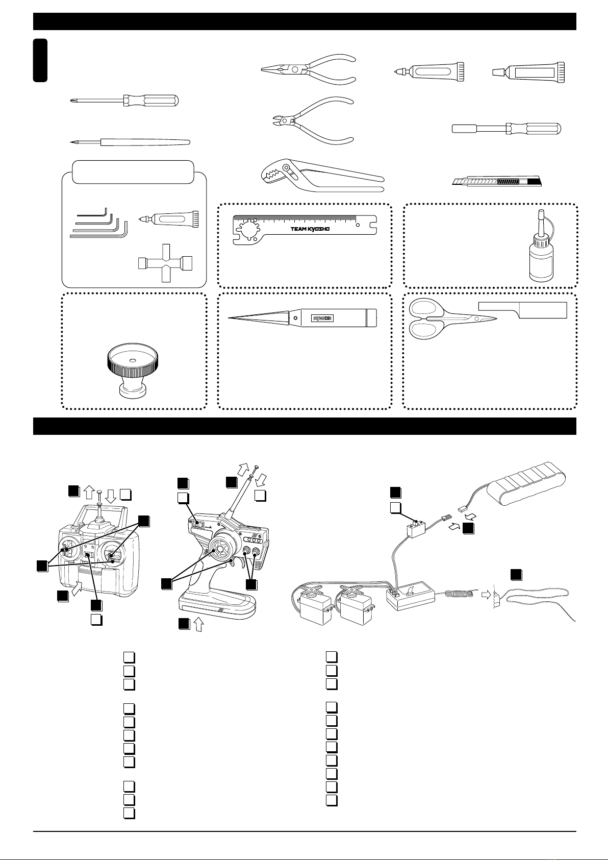
キットの内容をお確かめください。万一不良、不足がありましたら、お買い求めの販売店にご相談いただくか、当社「ユーザー相談室」までご連絡ください。
Check all parts. If you find any defective or missing parts, contact your local dealer or our Kyosho Distributor.
2
説明書の見かた
How to read the instruction manual:
3
No.4, No.5, No.6
5 x 10mm メタル
Metal Bushing
4
キングピン
King Pin
4
5.8mm ピロボール(黒)
Pillow Ball (Black)
2
3
6
小物部品のキーNo. 名前、
原寸図、使用数。
Key Number, Part Name,
True-to-scale Diagram,
Quantity Used
説明書内では多くのマークが使用
されています。マークに注意して
組立てを進めてください。
This instruction manual uses seve-
ral symbols. Please note them
during the entire assembly.
キット内の部品は、ビス類を除
いてキーNo.が付けられています。
スペアパーツを購入する時は
キーNo.を参照してください。
All parts except screws are identified
by key numbers. For purchasing
spare parts, find the key no. of the
part needed in the spare part list and
refer to the left column to look up the
corresponding order no.
説明書に使われているマーク
Symbols used throughout the instruction manual, comprise:
4
瞬間接着剤で接着する。
Apply instant glue
(CA glue, super glue).
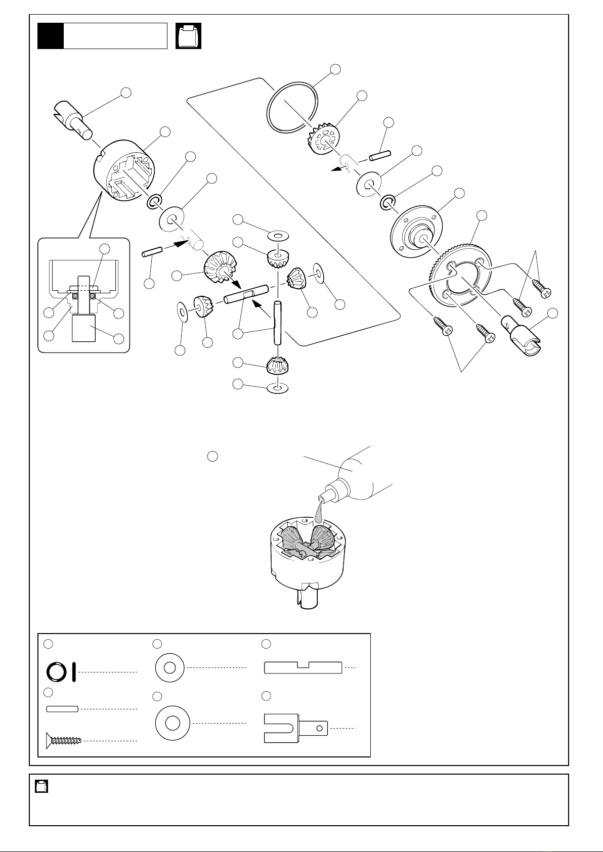
グリスを塗る。
Apply grease.
ネジロック剤を塗る。
Apply threadlocker
(screw cement).
2セット組立てる(例)。
Assemble as many times as
specified (here: twice).
x2
左右同じように組立てる。
Assemble left and right sides
the same way.
原寸図
True-to-scale diagram.
別購入品
Must be purchased separately!
仮止め。
Tentatively tighten.
2mmの穴をあける(例)。
Drill holes with the specified
diameter (here: 2mm).
可動するように組立てる。
Ensure smooth non-binding
movement while assembling.
注意して組立てる所。
Pay close attention here!
4
5
6
4
5
1
7
5
8
2
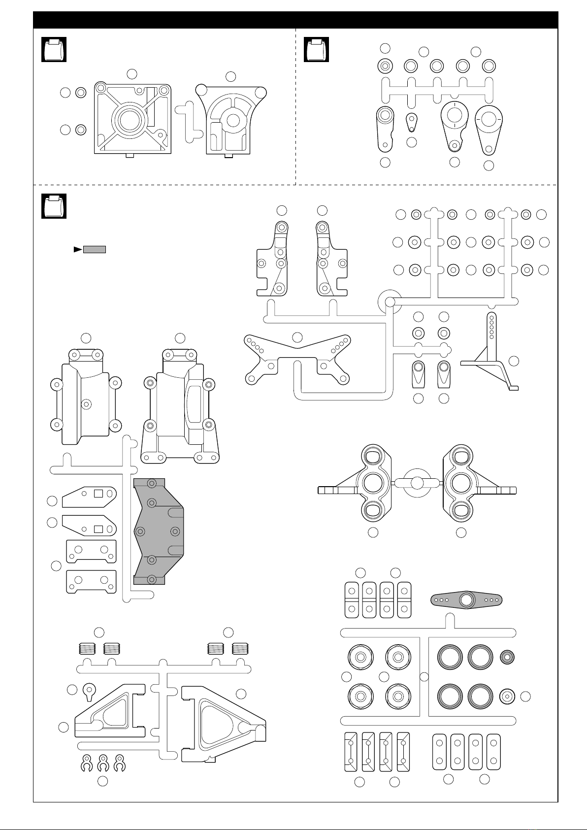
使用する袋詰。
Part bags used.
をカットする。
Cut off shaded portion.
フロントサスペンション
Front Suspension
1
2mm
ゴム系接着剤で接着する。
Apply rubber cement.
〔説明例 Example〕
BRG007F
オプションのベアリング
の品番。(例 : No.BRG007F)
Ball bearings are optional!
(with optional part no.)
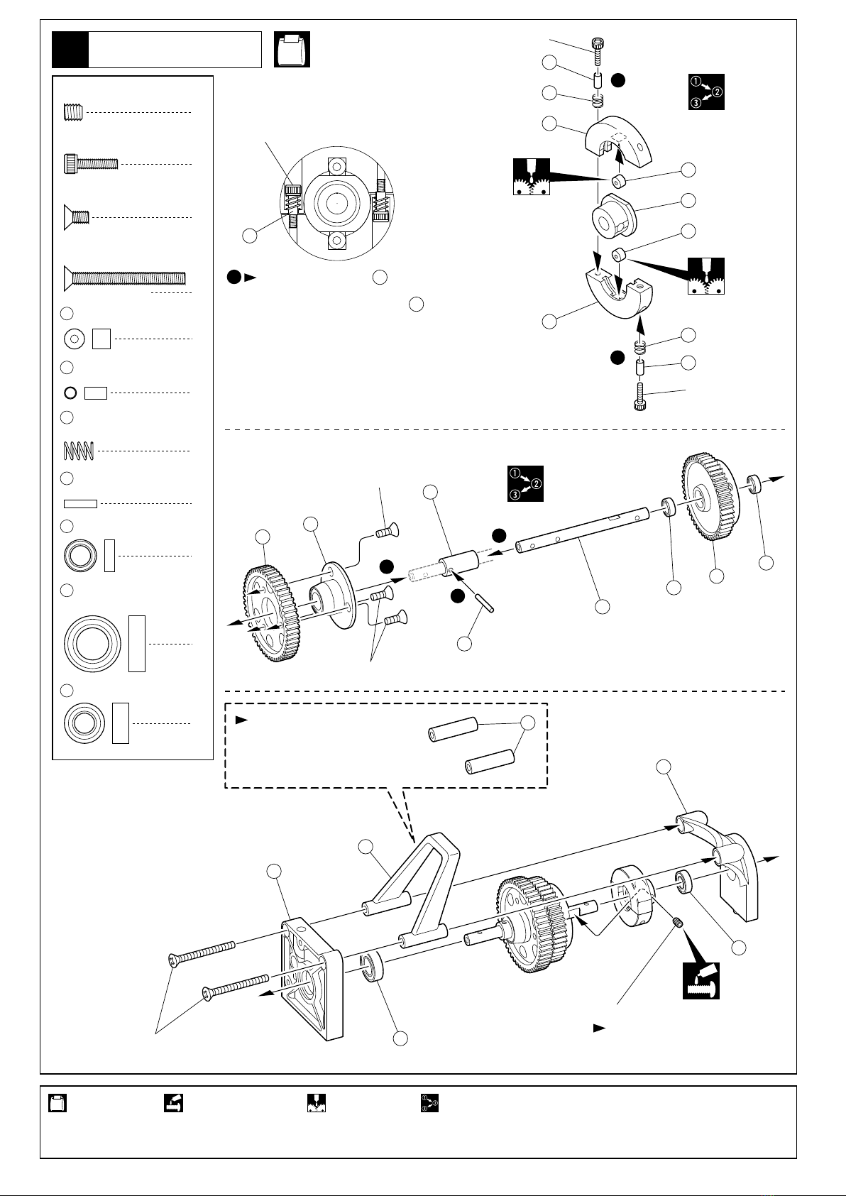
番号の順に組立てる。
Assemble in the specified
order.
TPビスは、部品にネジを切りながらしめつけるビスです。しめこみが固い場合が
ありますが、部品が確実に固定されるまでしめこんでください。 ただし、しめす
ぎるとネジがきかなくなりますので、部品が変形するまでしめないでください。
Self-tapping (TP) screws cut threads into the parts when being tightened. Excessive force may
permanently damage parts when tightening TP screws. It is recommended to stop tightening when
the part is attached or when some resistance is felt after the threaded portion enters the plastic.
6
ビスがきかない
The threads are stripped.
しめすぎ
Overtightened.
Correct
Wrong
キットには、形や長さが違うビスや小物部品が多く入っています。説明書には原寸図がありますので確認してから
組立ててください。また、ビス類は多めに入っているものもありますので、予備としてお使いください。
This kit contains screws and hardware in different metric sizes and shapes. Before using them, check the screws on the true-to-scale diagrams
on the left side in each assembly step. Some screws are extras.
5
●ビスの種類 SCREWS
ビス
Screw
キャップビス
Cap Screw
3x12mm サラビス
F/H Screw
TPビス
Self-tapping (TP) Screw
TPサラビス
TP F/H Screw
セットビス
Set Screw
●小物部品のサイズ例 OTHER HARDWARE
3x12mm ビス
Screw
3mm
12mm
3mm
12mm
サラビス
Flat Head (F/H) Screw
3mm ワッシャー・ナット
Washer・Nut
3mm
5x10mm メタル・ベアリング
Metal Bushing・Bearing
5mm
10mm
4mm
E4 Eリング
E-ring
5.8mm ピロボール
Pillow Ball
5.8mm
4