L-Card ADC Series User manual


Revision history of this document
Date
Document
revision
Contents of the change
09.2014
1.0.0
Preliminary data
05.2015
1.0.1
The operating temperature range has been changed (
fig. 1-1
),
upgraded Chapter 2, Chapter 4. Added section 4.8, Chapter 7,
technical data corrected – Chapter 5.
05.2016
1.0.2
Order option E-502-X-EU-X has been added to the section 1.1.
10.2016
1.0.3
Fixed bugs in the drawings 6.3
01.2017
1.0.4
Information on the industrial design version is included. Amended fig.
1-1
.
01.2017 1.0.5 The error about the presence of pull-up resistors on DI inputs is
corrected (s.
5.3
,
6.3
)
01.2017
1.0.6
The operating temperature range in the table of section 5.9 has been
brought into correspondence, amended the section 5.8, the tables in
subparagraphs
1.1.1
are amended,
2.1
02.2017
1.0.7
Paragraph added 3.3.4.1
06.2017
1.0.8
Comments are added to sec. 2.3.3, section is added. 2.8
06.2017
1.0.9
A warning is added to item.
3.3.5.2
10.2017
1.1.0
Added industrial design versions.
The characteristics according to the results
of preparation of the family of L-CARD voltage measuring converters
for certification as Means of Measurement are brought into
correspondence.
Added to item
3.3.8
. Paragraph added
4.7
When reading this documentelectronically, to facilitate navigation,use the electronic tree
ofthe table of contents (for example,AcrobatReader),as well ashyperlinks within the document.

Contents
CHAPTER 1. GENERAL DESCRIPTION................................................................... 7
1.1. Order information............................................................................................................... 8
1.1.1. Distribution kit ................................................................................................................... 9
1.2. Appearance and main structural elements ................................................................... 10
CHAPTER 2. INSTALLATION AND CONFIGURATION. ....................................... 11
2.1. E-502 configuration "by default"...................................................................................11
2.2. Internal construction elements and E-502 configuration...........................................12
2.2.1. Configuration of the DAC outputs of the connector Analog (DAC1/+15V/AGND/NC
and DAC2/-15V/DGND/NC)....................................................................................................... 13
2.2.2. Configuration of the resolution of the active state of the digital outputs DO1 ... DO16
on the Digital connector................................................................................................................ 13
2.3. Functions of the status LEDs on the front panel..........................................................13
2.3.1. LED1................................................................................................................................. 13
2.3.2. LED2................................................................................................................................. 14
2.3.3. LEDS Link and Activity (on LAN connector) in modifications E-502-P-EU.............14
2.4. RESET functions............................................................................................................... 14
2.5. Serial number. E-502 version number. Module identification in a multi-module
configuration................................................................................................................................ 15
2.6. E-502 application as a part of user programs...............................................................15
2.7. Software installation ......................................................................................................... 15
2.8. Ethernet interface configuration ....................................................................................15
CHAPTER 3. THE MECHANISM AND PRINCIPLE OF OPERATION OF E-502.. 16
3.1. Conventions........................................................................................................................ 16
3.1.1. Convention on numbering............................................................................................... 16
3.1.2. The assumption on the concept of "frequency" .............................................................16
3.2. Introduction (general information)................................................................................ 16
3.3. Operation principle........................................................................................................... 17
3.3.1. Reference frequency ........................................................................................................ 18
3.3.2. ADC channel.................................................................................................................... 18
3.3.3. Digital input channel........................................................................................................ 19
3.3.4. Digital output and DAC channels ................................................................................... 19
3.3.5. E-502 synchronization general principle........................................................................20
3.3.6. Adjustment of theratio between the time of setting the signal and the resolution for
each ADC channel......................................................................................................................... 22
3.3.7. Relative switching delays in ADC channels. .................................................................23
3.3.8. Relative delays of the ADC, DAC and I/O channels.....................................................25
3.4. Operation principle and function circuit.......................................................................27

3.5. All functional differences of E-502 and L-502..............................................................29
CHAPTER 4. CONNECTION OF SIGNALS. ........................................................... 30
4.1. DGND, AGND circuits..................................................................................................... 30
4.2. GND, 0 V, GND_USB, CHASSIS circuits.....................................................................30
4.3. Location of DGND, AGND, GND, 0 V, GND_USB, CHASSIS circuits on the board
30
4.4. E-502 connectors description .......................................................................................... 31
4.4.1. Connector Analog. ........................................................................................................... 31
4.4.2. Connector Digital............................................................................................................. 34
4.4.3. JTAG connectors of Blackfin processor......................................................................... 39
4.4.4. Connectors JTAG and UART0 of the ARM controller LPC-4333 (LPC-4337).........39
4.5. The maximum allowable conditions at the inputs and outputs of signal lines........40
4.6. ADC input operation voltage range ...............................................................................41
4.7. Preconditions for correct connection and correct settings of the input of the ADC
E-502.............................................................................................................................................. 43
4.7.1. The physical causes of possible problems...................................................................... 43
4.7.2. Conditions for correct E-502 connection and settings...................................................43
4.8. Calculation of total load power of E-502 output circuits............................................44
CHAPTER 5. SPECIFICATIONS.............................................................................. 46
5.1. ADC..................................................................................................................................... 46
5.1.1. Limits of the permissible relative basic error of measuring the AC voltage................47
5.1.2. ADC own input noise. ..................................................................................................... 47
5.1.3. ADC inter-channel passing.............................................................................................. 48
5.2. DAC..................................................................................................................................... 48
5.2.1. AC voltage playback error............................................................................................... 48
5.3. Digital inputs...................................................................................................................... 49
5.4. Digital outputs.................................................................................................................... 50
5.5. Synchronization in E-502................................................................................................. 50
5.6. Characteristics of standard interfaces...........................................................................51
5.7. Power supply system and galvanic isolation.................................................................52
5.8. Construction specification. .............................................................................................. 53
5.9. Environmental conditions................................................................................................ 53
5.9.1. Normal conditions............................................................................................................ 53
5.9.2. Operating conditions........................................................................................................ 53
CHAPTER 6. CONNEXION SAMPLES.................................................................... 54
6.1. ADC entry point connection............................................................................................ 54

6.1.1. Connecting to the ADC entry point of single-phase voltage source.............................54
6.1.2. Connection to ADC input with up to 16 differential voltage sources ..........................57
6.1.3. Connection to the ADC input for the case where the common wire of the signal
sources has a offset potential Ucm of max. ± 1 V relative to the AGND circuit.....................58
6.1.4. Measurement of the voltage drop on the circuit section in the differential mode (up to
16- channels).................................................................................................................................. 58
6.1.5. Differential connection of the transformer (throttle) winding with midpoint and offset
potential with respect to AGND................................................................................................... 59
6.1.6. Example of mixed connection of voltage sources "with common ground" and
differential...................................................................................................................................... 59
6.1.7. Connecting a power supply to the ADC input............................................................... 59
6.1.8. The coordinated connection of remote sources of current or voltage through a long
line with a wave impedance Zw................................................................................................... 61
6.1.9. The coordinated connection of a remote voltage source through a pair of long line
with a wave resistance Zw with matching on the signal source side.........................................62
6.2. Connecting the DAC outputs...........................................................................................63
6.2.1. Mode "with common ground" 2-channel output ±5 V .................................................. 63
6.2.2. Single-channel differential output ±10 V....................................................................... 63
6.3. Connecting the digital inputs and outputs. ...................................................................64
6.3.1. Connecting the LED or the optron input. Option 1........................................................ 64
6.3.2. Connecting the LED or the optron input. Option 2........................................................ 64
6.3.3. Connecting a contact to a digital input ........................................................................... 64
6.3.4. Connect the optron output to the synchronization input................................................ 64
CHAPTER 7. DESIGN DATA ................................................................................... 65
7.1. Circuit plate draft. ............................................................................................................ 65
7.2. Front panel draft............................................................................................................... 66
7.3. Back panel draft................................................................................................................ 66

Chapter 1. General description.
L-Card presents a data collection system E-502 on the basis of USB and Ethernet interfaces.
E-502 – is a system developed by LLC "L-Card". It is made on the basis of high quality production
of the company, it provides its own technical support and maintenance.
E-502 has the continuity of architecture with L-502: only the interface with the PC with the
same functionality as the L-502 is subjected to processing, except for the small functional
differences that will be discussed in this manual (s. 3.5, p. 29). The E-502 and L-502 software has
also has continuity (common library functions of the upper software level of the PC, identical to
the software at the Blackfin level).
The most important characteristics of E-502:
•ADC: 16 bits, conversion frequency up to 2 MHz, with switching to 16 differential channels or 32
channels with common ground. Subranges: ±10 V”, “±5 V”, “±2 V”, “±1 V”, ±0.5 V, ±0.2 V.
•Modification E-502-…-…-D has DAC support: 16 bits, 2 channels, output ± 5 V, asynchronous or
synchronous mode with a conversion frequency of up to 1 MHz for each channel.
•Digital input: up to 17 digital inputs of general purpose, asynchronous or synchronous data output
mode with a frequency of up to 2 million words per second.
•Digital output: up to 16 digital outputs of general purpose, with separate control of the output
resolution of the high and low byte, asynchronous or synchronous data output mode with a frequency
of up to 1 million words per second.
•Processor (modification E-502-P-…) Blackfin 530 MHz, SDRAM 32 MB, the JTAG connector
allows to activate ready "advanced" signal processing and control functions inside the E-502 or
independently to be engaged in low-level programming of these functions.
•Galvanic isolation provides isolation of digital and analogous signal inputs/outputs to all computer
circuits.
•The system can consist of one or more E-502 modules, synchronized from each other, from an internal
or external synchronization source with an ADC conversion frequency of up to 1.5 MHz.
•Design version "I" (E-502-…-…-…- I) has an industrial temperature range and a lacquer seal.
The E-502 notation system is given in fig. 1-1.

E-502- - - -
Модификация
преобразователя
P- Процессор Blackfin 500 МГц, ОЗУ
32 МВ и порт JTAG присутствуют
X- Отсутствуют процессор Blackfin,
ОЗУ и разъём JTAG
U
EU
D
X
ЦАП (2 канала)
присутствует
ЦАП
отсутствует
Преобразователи напряжения
измерительные
I+5…+55
°
С
-40…+60
°
С
С лакировкой
Нет
индекса
USB 2.0
Ethernet 100 Мбит/с
USB 2.0
Fig. 1-1. The notation system of the E-502 module
1.1. Order information
The E-502 versions and design versions available for ordering:
E-502-P-EU-D-I,
E-502-P-EU-D,
E-502-X-EU-X,
E-502-X-U-D,
E-502-X-U-X.
When choosingthe modificationoftheE-502 module for the order, it should be noted that when
you contact the L-Card sales department, the previously purchased E-502 module can not be
modified to another modification or design version.
Information on other modifications and design versions you can find in the L-Card sales
department (en@lcard.ru).
No DAC
DAC (2 channels)
yes
- There is no Blackfin RAM processor
and JTAG connector
- There is Blackfin processor 500 MHz,
RAM, 32 MB, and JTAG connector
Mbit/s
Measuring voltage
converters
No
index
With polish
Converter
modification

1.1.1.Distribution kit
Except for the E-502 module, the distribution kit includes the following accessories, depending
on the version:
Accessory Quantity
Note
E-502-
P-EU-D-I,
E-502-
P-EU-D,
E-502-
X-EU-X
E-502-
X-U-D
E-502-
X-U-X
DB-37F connector 1 pc. 1 pc. 1 pc. Cable receptacle
DB-37M connector 1 pc. 1 pc. 1 pc. Cable plug
Cover DP-37C 2 pcs. 2 pcs. 2 pcs. For DB-37 connectors
DJK-10A straight connector 1 pc. 1 pc. 1 pc. To connect low-voltage power
from a non-standard power
source.
Cable Ethernet Pathcord 5e,
L=1.5 m 1 pc. −−
USB cable, type A-B, L=1.8
m 1 pc. 1 pc. 1 pc.
Power adapter network
adapter ~ 220V/ = 12V,
0.5A, unstabilized
1 pc. 1 pc. 1 pc. Linear transformer power supply
for mains supply ~220 V, 50 Hz
Jumper 2 pcs. 2 pcs. 2 pcs. For all E-502 jumper
modifications, the enable
configuration of the digital
outputs is included.
The remaining jumpers are pre-
installed inside the E-502 by
"default", s. 2.1, p. 11

1.2. Appearance and main structural elements
Fig.1-2. Front view (front panel)
Fig.1-3. Back view (back panel)

Chapter 2. Installation and configuration.
2.1. E-502 configuration "by default".
E-502 comes with presets "by default" corresponding to the table below.
Configuration E-502-P-EU-D
E-502-P-EU-D-I
E-502-X-U-D
E-502-X-U-X
E-502-X-EU-X
Setting the resolution of the
high and low byte of DO
digital outputs on the
Analog connector
Programmed
control
(no jumper on
fig. 2-1 on the
left)
Programmed control
(no jumper on fig.
2-1 on the left)
Programmed control
(no jumper on fig. 2-1
on the left)
Output setting
DAC1 / +15V / AGND / NC
on Analog connector
DAC1
(See fig. 2-1)
DAC1
(See fig. 2-1)
NC
(See fig. 2-1)
Output setting
DAC2 / -15V / GNDD / NC
on Analog connector
DAC2
(See fig. 2-1)
DAC2
(See fig. 2-1)
NC
(See fig. 2-1)
"L-Card" installs this configuration usingjumpers on the board (fig. 2-1) – inside the pack. See
configuration explanation in subsection 2.2.1, 2.2.2.
Note: How to programmatically resolve the Ethernet interface, explained in p. 2.8.

2.2. Internal construction elements and E-502
configuration.
Fig. 2-1. Internal configuration
Note to fig. 2-1: in modules E-502-X-U-X, E-502-X-EU-X (without DAC), state of DAC1 or DAC2
is equivalent to the unconnected state of this output.
Attention! Technological connectors are not designed for user connections.
To access the elements of the internal structure, carefully remove the rubber feet from the
bottom of the chassis, unscrew the 4 screws and disassemble the housing covers. Reassemble in the
reverse order.
Настройка выхода
DAC1 / +15V / AGND
DAC1
(см.
примеч.)
+15V
AGND
Настройка выхода
DAC2 / -15V / GNDD
DAC2
(см.
примеч.)
-15V
AGND
1
JTAG
Blackfin
JTAG
ARM
1
1
UART ADSP-
BF523
FPGA
Cyclone
IV
SDRAM
SDRAM
ARM
LPC4337
CPLD
RESET LAN
USB
+8…+30 VD I G I T A L
Элементы
ЦАП
Настройка разрешения
цифровых выходов DO:
Программное
управление
(по умолчанию)
DO1...16
активны
DO1...8 активны
DO9...16 программно
управляются
DO9...16 активны
DO1...8 программно
управляются
A N A L O G
NC (не
подлючён)
Гальванический
барьер
NC (не
подлючён)
Техноло-
гический
разъём
Технологический
разъём
DO1...8 active DO9...16
software controlled
Output setting
Output setting
Galvanic
barrier
Technological
connector
DAC
elements
Technological
connector
Programmed
control
(by default)
DO1... 8 software
controlled
DO9...16 active
DO1...16
active
NC (not
connected)
NC (not
connected)
(see
note)
(see
note)
Setting the resolution of DO
digital outputs:

2.2.1.Configuration of the DAC outputs of the connector Analog
(DAC1/+15V/AGND/NC and DAC2/-15V/DGND/NC)
If your modification E-502 (fig. 1-1)has DAC, then "by default" the DAC within E-502 should
be connected tocontacts 18 and 19 of the connector Analog (fig. 4-3, p. 32).
If necessary, you can independently change the configuration of these outputs by rearranging
the jumpers, according to fig. 2-1.
Analog connector isdescribed in section 4.4.1,p. 31.
2.2.2.Configuration of the resolution of the active state of the digital outputs
DO1 ... DO16 on the Digital connector.
Activation of the digital outputs on the Digital connector (fig. 4-4, p. 34) is done in a
programmatic way "by default", and, as practice shows, users are satisfied in the overwhelming
majority of cases.
But, if necessary, digital outputs can be activated at power-up (without the possibility of
programmed transfer to the third state) – in thiscase, you need toinstall one ortwoadditional jumpers
according to fig. 2-1. This setting is made when the initial high-impedance state of the digital outputs
is not permissible for the connected load.
2.3. Functions of the status LEDs on the front panel.
2.3.1.LED1.
Usually LED1 on the front panel indicates a status of the module data collection:
LED1 state Description
Red light E-502 is connected and in the synchronous I/O standby mode.
Green light E-502 is in the synchronous I/O mode.
No lights Power is off.
In case of using more than one E-502 module, the user faces the task of identifying the module
with which the program is currently running. To solve this problem in a visual manner, you can use
the software function of controlling the red glow of LED1. Of course, the task of automatic module
identification can be solved with software, reading the module's available serial number.
Note: behavior of LED1 on E-502 is identical to the behavior of LED on the L-502 panel.
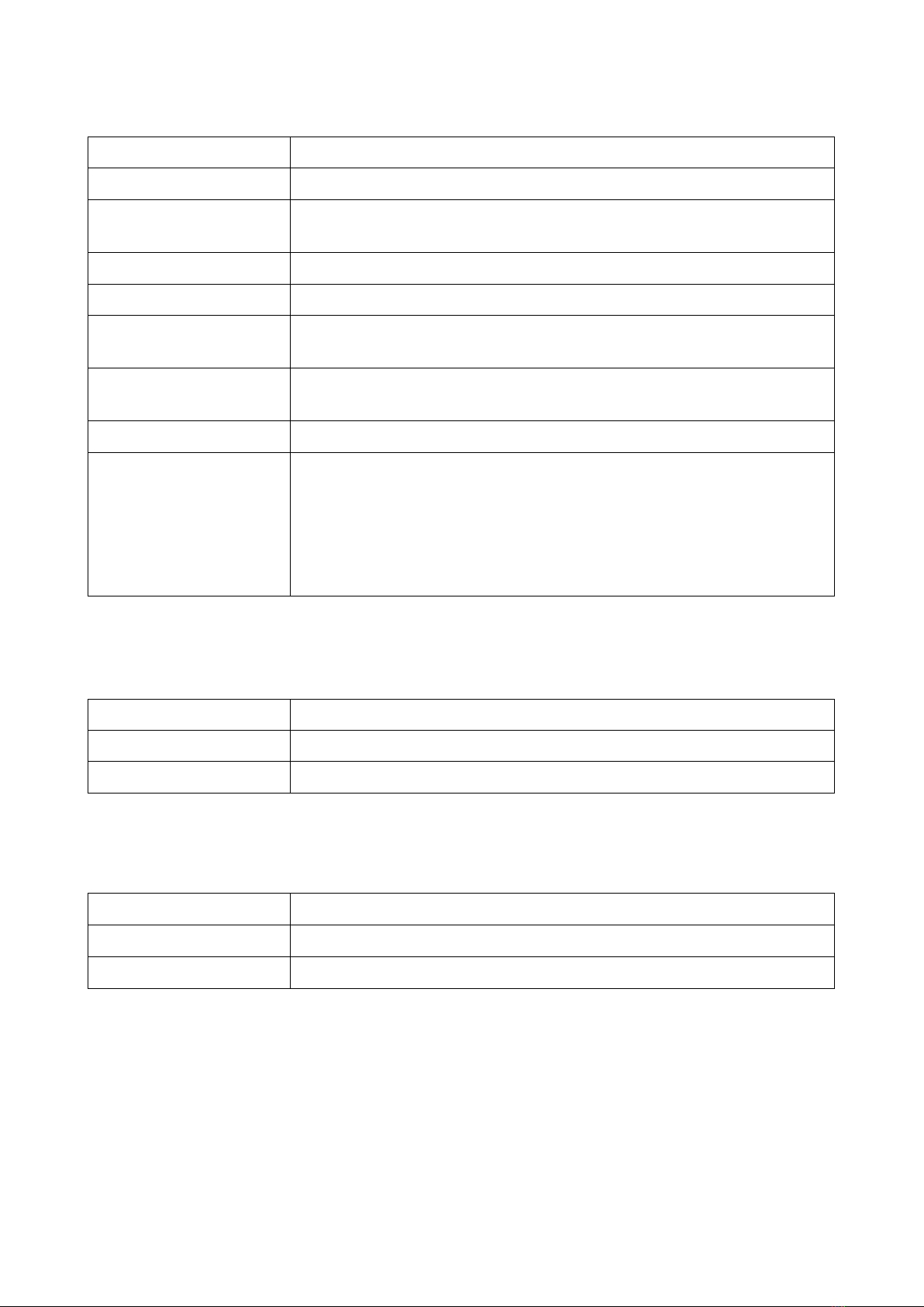
2.3.2.LED2.
The LED2 on the front panel indicatesthe state of USB interface
LED2 state Description
Constant red light There is a USB connection at the Full-Speed (up to 12 Mbit/s)
Non-periodic short red
light Data transfer via USB at the Full-Speed (up to 12 Mbit/s)
Constant green light There is a USB connection at the High-Speed (up to 480 Mbit/s)
Variable green light Data transfer via USB at the High-Speed (up to 480 Mbit/s)
Yellow orange light
No USB connection (no cable connected, no drivers installed or the PC
operational system has not found a USB-device E-502)
Periodically changing
red-green glow E-502 is in the service "bootloader" mode, or after holding RESET
button, or in the software update process.
No lights Power is off
Slow periodic red light
after power is on SDRAM test error.
If the E-502 got into this stateafter power-
up, this couldbe either a sign
of E-502 failure or a sign of the heavy external electromagnetic
environment in which the E-502 is located, which led to a malfunction.
Contact the "L-Card" technical support if the E-
502 gets into this state
after turning on the power.
2.3.3.LEDS Link and Activity (on LAN connector) in modifications E-502-P-EU.
Link LED status Description
Yellow glow Connected to Ethernet
No glow No Ethernet connection
Note: in the current manufactured products, the opposite logic of the LINK LED illumination
is possible (this feature is not a malfunction of the E-502). But, in any case, if E-502 is programmed
to operate with USB, Link and Activity LEDs will not glow.
Activity LED status Description
Green glow Data transmission via Ethernet
No glow No data transmission via Ethernet
How to programmatically resolve the Ethernet interface, explained in p.2.8.
2.4. RESET functions
The secret reset button is used to reset the ARM controller, after which the E-502 will normally
restart the ARM-controller. For a normal restart, briefly press the RESET button.

The "loader" service mode will be activated after holding the RESET button for at least 10
seconds. The periodically changing red-green glow of LED2 indicates that the E-502 is in the
bootloader mode.
2.5. Serial number. E-502 version number. Module
identification in a multi-module configuration.
The unique eight-digit product serial number (on the label on the bottom of the case) serves to
identify the module instance within itslife circle. E-502 serial number is program-available.
2.6. E-502 application as a part of user programs
LLC "L-Card" supports integration of its modules in the user systems. But when E-502 is
included in any system, the system developer must mention in the documentation for his system the
E-502 module of the "L-Card" production, as the component part (the completing unit).
2.7. Software installation
To install the necessary drivers and libraries for Windows OS, you must download and run the
installer "L-Card L502 / E502 SDK" http://www.lcard.ru/download/lpcie_setup.exe.
For information on installing the driver and libraries under Linux OS, see
http://en.lcard.ru/download/x502api.pdf.
2.8. Ethernet interface configuration
To work with E-502 module via Ethernet, it is required to make settings and resolution of this
interface in the program "L-Card Measurement Studio" (https://bitbucket.org/lcard/lqmeasstudio/ ),
connecting the module via USB. If Ethernet interface is not permitted, the E-502 module will not
respond to the connection of Ethernet cable (both LEDs Link and Activity on the LAN connector
will be turned off).

Chapter 3. The mechanism and principle
of operation of E-502.
3.1. Conventions
3.1.1.Convention on numbering
In all products of the L-Card, the numbering of all physical objects (for example, channel
numbers) in the description of the principle of action and design is always made from one!
This agreement is completely unrelated to the encoding method in programming, where the
numbers of these physical objects can be encoded from scratch or otherwise, in the context of the
corresponding library function or programming language.
3.1.2.The assumption on the concept of "frequency"
In the documentation for E-502, the frequency of discrete signals (e.g., synchronization signals)
is expressed in Hertz, and not in periods per second, as it is common for frequency for a non-
sinusoidal process.
3.2. Introduction (general information)
All modifications of E-502 (fig. 1-1, section 1.1) are made on the basis of the same multilayer
PCB. Modification is achieved by different variants of the factory assembly. Changing E-502
modifications after factory assembly is not provided for.
The presence of the ADSP-BF523 signal processor with SDRAM (modification E-502-P-░-░) is
considered justified for those users who want to get the maximum of on-board signal processing
capabilities on-board, as well as for advanced users to have their own low-level programming of the
processor, possibly with the use of the JTAG-emulator (s.4.4.3, p. 39).
All E-502 modifications have a galvanic isolation of the signal circuits (for L-502 a galvanic
isolation is an option).
DAC with 2 channels (modification E-502-░-░-D) allows to display output analog voltage
levels or voltage time functions.
ADC 16 bits with a conversion frequency of up to 2 MHz with 16/32-channel circuit
switching (up to 16 differential channels, up to 32 with a common ground) with voltage subbands
of ±10 V, ±5 V, ±2 V, ±1 V, ±0.5 V, ±0.2 V has an analog ADC path, identical to L-502,
with a maximum conversion frequency of 2 MHz.
Note the limitations up to± 1 V of the operating range of the input signal on the Y and GND32
inputs (for details, see 4.6).
Instrumental DAC 16 bits2 channels ±5 V provides the opportunity of synchronous (streaming
up to 1 MHz for a channel), asynchronous mode on the selected DAC channel, including mixed
synchronous asynchronous mode on different channels, as well as a cyclic synchronous self-oscillator
from the E-502 internal buffer (2 pages of 1.5 Mcounts.)
Digital output, 16 lines. Similarly to a DAC, it is possible to have a synchronous output of up
to 1 MHz, as well as an asynchronous output, as well as a synchronous output from an internal buffer.
With synchronous output, the frequency is matched to the frequency of the DAC output. The output
enable allocated for the low and high byte increases the flexibility of using digital lines, for example,

configuration is possible: 8-bit 2-directional data bus + up to 8 data bits per input + up to 8 data bits
per output. This allows the implementation of controlling bus diagrams for complex digital
devices (sec. 4.4.2.2, p.38).
!
With synchronous output to the DAC to d
igital output, operation only in the same
synchronous mode is supported: in the mode of streaming output, or a self-oscillator from
the internal buffer. At the same time, you can work asynchronously with any output
channels.
Note the limitations of the asynchronous output for external synchronization (n.3.3.4.1).
Digital input, up to 17 lines, synchronous mode of up to 2 MHz or asynchronous one. In
synchronous mode, the stream from digital lines is synchronous with the ADC stream, but separate
and independent of the settings of the ADC data collection frame (the frequency of data collection by
digital lines is set separately and does not depend on the ADC frame settings).
It should be noted that in the E-502, the three highest digits in the group of digital inputs (DI14,
DI15, DI16) have alternative synchronization functions (table 4-2).
The ADC, DAC, digital input and output streams are synchronized with respect to the same fref
reference frequency, which can be assigned programmatically: 1.5 MHz or 2 MHz.
Hardware-wise, in E-502, the physical frequency of the ADC and the synchronous digital input
is always equal to fref, and the physical refresh rate of each DAC channel and digital output is fref/2.
Getting all the fractional frequences of the data input fref/n and fref/2m output fractional frequencies
(where m and n are natural numbers) occurs at the hardware processing level in the FPGA and/or in
the Blackfin processor.
E-502 hasa mechanism ofthe intermodule synchronization (s.3.3.5, p. 20)toform a single
synchronous I/O system.
E-502 has a 32-bit data word format, in the format of which, besides the actual data for input
or output, there is also a physical channel number. This hardware binding of the physical channel
number ensures that the channel number is mistaken even if the top-level program for some reason
lost an arbitrary amount of data.
For advanced users: HOST DMA access mode to the internal memory of the signal processor
ADSP-BF523 allows you to apply an independent access channel to the Blackfin internal memory.
This creates a huge convenience - "transparency" with low-level Blackfin programming - to see what
happens in Blackfin memory on an independent channel. To some extent, HOST DMA can replace
JTAG (the convenience of the technology of independent access channel in the signal processor
memory has been evaluated by users even in products E-440/ E14-440 by L-CARD!).
Operation modes with E-502 via USB or Ethernet are alternative. E-502 uses 32 bit data words
for a transmission via interfaces (in each word the data is counted with the index part).
When using USB, the E-502 has a bandwidth limitationof 5 Mcounts/ s High-Speed, which
must be taken into account while applying the E-502.
When operating via Ethernet, the E-502 has a 2.5 Mcounts/s bandwidth limit on the input.
The interface function (USB, Ethernet) in E-502 is performed by a separate 2 cores ARM
controller LPC4333/4337, which has a separate JTAG connector on the board and an independent
additional UART0 port.
3.3. Operation principle
In section 3.2the general information about E-502 was summarized, in this section further
details are presented. This section in many respectsrepeatsa similar section of the manual L-502 due
to the similarity of these projects.

3.3.1. Reference frequency
fref – a signal reference frequency, from which the conversion processes are synchronized to
the ADC, DAC, digital input and digital output. The E-502 uses a common reference frequency that
synchronizes the start-up of the ADC, DAC, digital input and digital output to an accuracy of an
integer division of this frequency. In E-502, thereference frequency source can be internal (2.0 or 1.5
MHz) or external (with a frequency of max. 2.0 MHz). In particular, the reference frequency from
the neighboring E-502 module can be used to form a synchronous multi-module system.
3.3.2.ADC channel.
The analog data input channel is a channel with dynamic switching up to 32 input physical
analog channels of the E-502 module to the input of a single internal ADC module. The process of
switching channels itself is hardware, according to a pre-configured control table. The input process
itself is conditionally divided into periodically alternating frame periods and interframe delay with
pre-configured durationsof these periods(interframe delay, in particular, can be set to zero). Duration
of frame, interframe delay, ADC output sample timing - all these times can be configured, but they
are always a multiple of tref= 1/ fref - the period of the synchronization reference frequency.
tsw = nsw / fref – the ADC channel commutation period within the frame, equal to the sampling
period of the ADC readouts, where nsw can be specified by an integer from 1 to 2097152
The preset number of samples in the frame and the size of the control table nк can be set from
1 to 256. In each cell of the control table, the physical number of the ADC polling channel is
prescribed. Within the frame, the control table will be read completely: from the 1st to the nth cell
and the read sequence of physical channels will be used in the hardware control mechanism of the
channel switch.
The cell number of the control table is called the logical channel number. Accordingly, logical
channels can be up to 256, and physical - up to 32. For example, it gives the opportunity to obtain a
different frequency of polling different physical channels within the frame.
Frame time: tk= nк* tsw = nк* nsw / fref
If necessary, between intermittently following frames, a non-zero interframe delay tdwith a
duration ndof synchronization frequency periods can be inserted:
td = nd*tref = nd /fref , where nd can be set with an integer from 0 to 2097151
The frame period is equal to the sum of the frame length and the interframe delay:
tch = tk +td = nк*nsw / fref + nd/fref
In other words, the frame period tch is equal to the period of data collection from the same
logical channel of the control table.
During interframe delay, the sample of control words does not advance, and the analog channel
switch is always set in accordance with the first cell of the control table.
Frequency of collection from one logical channel of the control table
fch = 1/ tch= fref /(nк* nsw+ nd),
where fref can be 2.0 or 1.5 MHz for an internal synchronization or ≤2.0 MHz for an external,
nк = {1,2,…, 256}, nsw ={1,2,…,2097152}, nd ={0,1,…,2097151}.
The above-mentioned frame structure of the ADC data is shown in fig. 3-1. Here, for example,
a 3-channel ADC mode operation (nк = 3) is taken with a non-zero interframe delay td.

Fig. 3-1. Illustration of the personnel principle for acquiring ADC data
3.3.3.Digital input channel.
Synchronous digital input occurs with a period of tref * ndin,
where ndin ={1,2,…,2097152} is a configurable frequency division factor for synchronous
digital input.
3.3.4.Digital output and DAC channels
Synchronous digital output, as well as updating both channels of the DAC, occurs with a period
of 2* tref. If the data buffer for the output and the DAC is empty, then the last value is held at the
outputs.
With any DAC channel and digital output, you can work asynchronously, with the other
channelsassigned as synchronous, the same synchronous mode is supported: either a streaming or an
self-oscillator from an internal buffer.
3.3.4.1. Restrictions on the current implementation of asynchronous output during
external synchronization.
Asynchronous output to digital lines and to DAC in the operating mode will always work when
configured for internal synchronization. But asynchronous output to digital lines and to the DAC will
not function in the standby mode for external synchronization of the start of data acquisition or
waiting for more than 1 μs of the external clock of the ADC conversion.
21
323
Канал 1
Канал 2
Канал 3
tk
nk=3
tdtk
tch
Кадр Межкадровая
задержка Кадр Межкадровая
задержка
tsw
1
Момент сэмплирования отсчётов данных АЦП
Номер
логического
канала АЦП
Sampling timing of ADC data
Logical
ADC
number
Channel 2
Channel 3
Channel 1
Interframe
delay
Interframe
delay
Frame
Frame

3.3.5.E-502 synchronization general principle.
The fig. 3-2 shows a simplified block diagram explaining the general device of the
synchronization system in E-502. E-502 synchronization system consists of two parts: primary and
secondary synchronization circuits.
3.3.5.1. Primary synchronization.
The primary synchronization circuit (I)according to the settings selects the corresponding
external or internal source of the reference frequency, as well as the external or internal source of the
start signal. Using the selected signals, circuit Igenerates an internal reference signal fref as a
sequence of synchronization pulses with a period tref. Moreover, the beginning of this sequence is
strictly bound by this scheme to the external or internal start event, and all I/O equipment is
synchronized (and simultaneously starts) from this sequence: nodes of the ADC (including the logic
of the control table), DAC and digital I/O. These nodes contain the corresponding frequency dividers
fref. We list all possible options for user settings related to the selection of sources of reference
frequency signals:
•Internal generator 2.0/ 1.5 MHz of this E-502 module (setting by default)
•The reference frequency from the DI_SYN1 input (on the front or on the drop)
•The reference frequency from the DI_SYN2 input (on the front or on the drop)
•The reference frequency from the CONV_IN input from the neighboring E-502, which acts as the
master.
We list all possible options for user settings for selecting sources of the start event of the E-502
I/O system:
•Program start from PC (default setting)
•On the signal from the input DI_SYN1 (on the front or on the drop)
•On the signal from the input DI_SYN2 (on the front or on the drop)
•By the signal from the input START_IN from the neighboring E-502, which acts as the master.
Each E-502 module always translates via its outputs CONV_OUT and START_OUT,
respectively, its internal reference and start signals for one E-502 slave module.
E-502 module can be, at the same time, the master for one or two adjacent modules and the
slave for the other adjacent E-502. Thus, synchronization of several E-502, connected by a chain, as
well as branching from one master to three slaves, is supported. The possible topology of
the synchronization circuits is discussed in detail in sec.4.4.2.1, p.37.
The primary synchronization circuit provides synchronization of the frequency and phase of
theADC, DAC and cycle cyclesof thedigital input andoutput system. It isunderstoodthat in a multi-
module synchronization system, the user will be able to intelligently set the control tables of different
modules, as well as the division of the reference frequency for the required input-output processes.
!
Note that for the slave E-
502 there is a frequency limitation at the input
CONV_IN – no more than 1.5 MHz. Thus, two or more slave E-502 modules
can be synchronized only at a reference frequency of 1.5 MHz from the master.
Stopping the primary synchronization scheme is done only programmatically and
asynchronously.
This manual suits for next models
6
Table of contents
Other L-Card Media Converter manuals


Popular Media Converter manuals by other brands


intinor
intinor Direkt receiver SDI user guide

HARVEST
HARVEST Nodestream AVR2 quick start guide

CYP
CYP AU-D250 Operation manual

Digital Barriers
Digital Barriers EDGEVIS IP Series Hardware installation guide

GoMax Electronics
GoMax Electronics MX-5004MZF user manual

Crestron
Crestron DM NVX 4K60 product manual

Alpha Technologies
Alpha Technologies LPR48-300 Installation & operation manual

Panduit
Panduit Atlona AT-HDR-M2C manual

DirectConnect
DirectConnect DCCVTDTARLA user manual

Euromag
Euromag MC608 Series installation manual

Honeywell Home
Honeywell Home PROSiXC2W Quick installation guide

PAC
PAC L.O.C.PRO LP3-4 installation instructions