Lütze CPSB1-480 Series User manual

Friedrich Lütze GmbH
Bruckwiesenstr. 17-19
71384 –Weinstadt –Germany
Tel.: +49 (0)7151 6053-0
Fax.: +49 (0)7151 6053-271
www.luetze.de
Friedrich Lütze GmbH
Bruckwiesenstr. 17-19
71384 –Weinstadt –Germany
Tel.: +49 (0)7151 6053-0
Fax.: +49 (0)7151 6053-271
www.luetze.de
Schaltnetzteile Serie Lütze CPSB1-480-xx
Betriebsanleitung
Hinweis!
Bevor Sie mit dem Gerät arbeiten, ist die Installationsanweisung sorgfältig und komplett zu lesen. Sie ist Bestandteil des Produktes und ist
stets griffbereit aufzubewahren.
Warnung!
Vor Beginn der Installations- oder Instandhaltungsarbeiten ist der Hauptschalter der Anlage auszuschalten und gegen Wiedereinschalten zu
sichern. Bei Nichtbeachtung kann das Berühren spannungsführender Teile, Tod oder schwere Körperverletzungen zur Folge haben.
Vor der Installation !
Der Betrieb des Gerätes ist nur für die vorgesehene Nennspannung erlaubt. Der Anschluss an anderen Spannungen kann zum Tod, schweren
Verletzungen oder zu erheblichen Sachschäden führen.
•Der Anschluss an die Versorgungsspannung muss gemäß VDE0100 und VDE0160 ausgeführt werden.
•Mit flexiblen Kabel: alle Litzen müssen ordnungsgemäß im Anschlussblock eingeklemmt sein (Kurzschlussgefahr).
•Das Gerät und das Netzkabel müssen geeignet abgesichert werden. Falls notwendig ist zusätzlich ein manueller Schalter
einzusetzen, um ein Freischalten zu ermöglichen.
•Der vorhandene PE-Anschluss ist zwingend anzuschließen.
•Alle angeschlossenen Leitungen müssen dem Strombereich des Netzteils entsprechen. Auf korrekte Polung ist zu achten!
•Ausreichende Kühlung muss gewährleistet sein
Modifikationen: Solange das Gerät betrieben wird bzw. an der Netzspannung anliegt, dürfen keine Modifikationen durchgeführt werden! Das
gleiche gilt auch für die Ausgangsseite. Folgen können sein : elektrische Lichtbögen oder elektrischer Schock!
Kühlung: Achtung Gerät nicht abdecken! Alle Lüftungsschlitze rund um das Gerät dürfen für eine ausreichende Kühlung nicht
abgedeckt werden.
Warnung:Hochspannung!
Das Gerät beinhaltet ungeschützte Bauteile, welche gefährliche Hochspannung führen bzw. Bauteile die diese speichern. Unsachgemäßer
Umgang kann zu Tod oder schweren Körperverletzungen führen! Das Gerät darf nur von qualifiziertem Fachpersonal geöffnet werden!
Stecken Sie keine Gegenstände in das Gerät. Halten Sie es von Feuer und Wasser fern.
Anwendung: Das primär getaktete Schaltnetzteil ist für die Montage auf DIN-Schienen (EN50022) konstruiert. Es ist auf eine saubere
Umgebung zu achten bzw. ist das Gerät vor Schwingung und Schock zu schützen. Die Installation darf nur von qualifiziertem
Personal erfolgen.
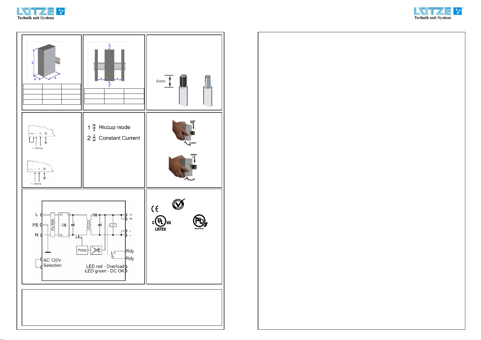
Montage: Die Montage hat nach Bild2a/2b zu erfolgen. Es ist auf eine freie Konvektion zu achten und sicherzustellen! Die Lüftungsschlitze
müssen zwingend den dort angegebenen Freiraum besitzen, um eine ausreichende Kühlung zu gewährleisten.
Befestigung : Kippen Sie das Gerät etwas nach hinten; setzen Sie es von oben in die Hutschiene ein ; Gerät gegen die Hutschiene drücken bis
es einrastet (Bild4). Kontrollieren Sie durch leichtes Rütteln, ob das Gerät fest sitzt.
LED Anzeige: „DC OK“ grüne LED : on = alle Ein-/Ausgangs Parameter sind ok.
Blinkend = Ausgang durch Überlast abgeschaltet
aus = Kurzschluss am Ausgang, keine Betriebsspannung vorhanden; interner Fehler
„Overload“ rote LED; on = Iout ≥ 1,1IN ; Überlast; Kurzschluss
Alarm Kontakt : Kontakt schließt mit Einschalten des Gerätes und wird bei Unterschreiten Uthreshold geöffnet (siehe Datenblatt)
Potentiometer: Einstellung der Ausgangsspannung. Achten Sie darauf, dass die Gesamtleistung (UAx IA) nicht die Geräte Nennleistung
überschreitet.
Redundanz und Parallel Betrieb: Die Geräte können im parallelen Betrieb eingesetzt werden. Um eine gleichmäßige Stromverteilung zu
bekommen, gleichen Sie die Ausgangsspannungen bei einem Strom von DC 1….2A auf Uout ±100mV ab. Für einen Redundanz Betrieb sind
externe Entkopplungsdioden z.B: 722999 zu verwenden.
Leitungsanschluss:
•Kabelquerschnitt und Abisolierung (sieheBild3)
•Nur Kabel verwenden, das der notwendigen Spannung und Strom entspricht
•Flexible Leitungen: alle Litzen müssen ordnungsgemäß geklemmt sein (Kurzschlussgefahr).
•Stellen Sie sicher, dass die Polung der Ausgangsklemmen korrekt sind
Erdung:
•Bei Class 2 Geräten ist kein PE Anschluss notwendig. Das Gerät kann in SELV und PELV Kreisen eingesetzte werden. Bei Class 1
Geräten ist eine Erdung auf der Eingangsseite zwingend durchzuführen. Zur Einhaltung der EMV und Sicherheitsbestimmungen
(CE,Zulasungen), dürfen Class 1 Geräte nur mit angeschlossenem PE betrieben werden.
•Ausgangsseitig ist keine Erdung erforderlich. Optional können die Ausgänge „ plus“ oder „minus“ geerdet werden.
Interne Sicherung:
Die Geräte besitzen keine Komponenten die durch den Anwender getauscht werden können oder dürfen. Bei einem Defekt des Gerätes ist
dieses auf jedem Fall an den Hersteller zurück zu senden.
Technische Daten :
Alle technischen gelten, wenn nicht anders angegeben bei Nennspannung, Nennlast und 25°C
Connection diagram AC 120V
Connection diagram AC 230V
Connection Jumper
Installation / installation
Anschlußquerschnitt / Nominal cross section
0,2mm2–4/6mm2 /AWG 10 –AWG 24
(60/75 class 1 copper)
Drehmoment / tightening torque
0,5 Nm –0,6 Nm
Konformitätserklärung / Declaration of conformity
Hiermit erklären wir, dass das Produkt mit den EU Standards übereinstimmt und das CE Zeichen
tragen darf.
We declare, that the product are in compliance with the EU standards, therefore they bear the CE
mark.
Maße / Dimensions : 480W
mm
inch
A
80
3,15
B
139
5,47
C
127
5,00
Abstände / Distances : 480W
mm
inch
A
50
1,97
B
10
0,40
Montage / mounting
Demontage / dismounting
Anschlussbild / Connection diagram:
Zulassungen / approvals
IND.CONT.EQ.4WX9
ROHS compliance:the product respects the EC
requirements related to ROHS substan-ces,
according to “Restriction of Hazardous
Substances” as perdocument 2011/65/UE
REACH compliance: the product respects the
EC requirements related to REACH SVHC
directive (2010)
Note:all the reported information comes from
our suppliers, F.Lütze GmbH. has not run any
test to evaluate if the specific elements are
present.

Friedrich Lütze GmbH
Bruckwiesenstr. 17-19
71384 –Weinstadt –Germany
Tel.: +49 (0)7151 6053-0
Fax.: +49 (0)7151 6053-271
www.luetze.de
Friedrich Lütze GmbH
Bruckwiesenstr. 17-19
71384 –Weinstadt –Germany
Tel.: +49 (0)7151 6053-0
Fax.: +49 (0)7151 6053-271
www.luetze.de
Switched power supplies series Luetze CPSB1-480-xx
Operating Instructions
Read Instructions!
Before working with this unit, read these instructions carefully and completely. Make sure that you have understood all the information!
Disconnect Warning !
Before any installation, maintenance or modification work: Disconnect your system from the supply network. Ensure that cannot be re-
connected inadvertently!
Before start of operation:
Warning! Improper installation / operation impair safety and result in operational difficulties or complete failure of the unit. The unit must be
installed and put into service by appropriately qualified personnel. Compliance with the relevant regulations must be ensured. Before
operation is begun the following conditions must be ensured, in particular:
•Connection to main power supply in compliance with VDE01000 and EN50178.
•With stranded wires: all strands must be secured in the terminal blocks (potential danger of short circuit).
•Unit and power supply cables must be properly fused; if necessary a manually controlled disconnecting element must be used
to disengage from supply mains.
•The non-fused earth conductor must be connected to the " PE " terminal (protection class 1).
•All output lines must be rated for the power supply output current and must be connected with the correct polarity.
•Sufficient air-cooling must be ensured.
In operation: No modifications: As long as the unit is in operation: do not modify the installation! The same applies also to the secondary
side. Risk of electric arcs and electric shock (fatal)! Only (dis) connect plug connectors when the power is off!
Convection cooling: Do not cover any ventilation holes! Leave sufficient space around the unit for cooling! See Fig. 2a/2b
Warning: High Voltage!
High voltage! Store energy! The unit contains unprotected conductors carrying a lethal high voltage, and components storing substantial
amounts of energy. Improper handling may result in an electric shock or serious burn!
•The unit must not be opened except appropriately trained personnel!
•Do not introduce any object into the unit!
•Keep away from fire and water!
Application : This unit is a primary switched-mode power supply designed for use in panel-board installations or building-in applications
where access to the supply is restricted (shock- hazard protection). It must only be installed and put into service by appro-
priately qualified personnel.
Mounting : Permissible mounting position: see Fig.2a/2b. The indicated space is a mandatory !
Snap on rail : Tilt the unit slightly rearwards. Fit the unit over top hat rail. Slide it downward until it hits the stop. Press against the bottom
front side for (see Fig. 4) locking. Shake the unit slightly to check the locking action.
LED indication: „DC OK“ green LED : on = all In-/Output parameter are ok.
flashing = output is cut off by overload
off = short circuit on the output side, no ac supply voltage; internal failure
„Overload“ red LED; on = Iout ≥ 1,1IN ; overload; short circuit
Alarm contact: contact is switched on with power on and open when Uout ≤ Uthreshold (see data sheet)
Potentiometer : Setting the output voltage. It´s not allowed to drive the power supply with more than the nominal power (Uout x Iout=480W
Redundancy and parallel operation : All devices can be used for an parallel operation. To get a good current share the output voltage of each
power supply must be adjusted that the difference between the voltages is ±100mV . The output current for these adjustment should be DC
1…2A. For a redundancy operation you must use an external diodes, for e.g. 722999.
Connection / Internal fuse:
•Data for permitted loads, cable cross-sections and stripping: see enclosed leaflet " Technical Data " (See Fig. 3).
•Use only commercial cables designed for the indicated voltage and current values!
•With flexible cables: make sure that all stranded cable are secured in the terminal.
•Ensure proper polarity at output terminals!
Grounding:
•Do not operate without PE connection! To comply with EMC and safety standards (CE mark, approvals), the unit must only be
operated if the PE terminal is connected to the non-fused earth conductor.
•Secondary side is not earthed; if necessary the “plus” or “minus” terminal can be earthed optionally.
Internal fuse:
The internal input fuse serves to protect the unit and must not be replaced by the user. In case of an internal defect, the unit must be
returned to the manufacturer for safety reasons.
Technical Data:
All specifications are typical at nominal line, full load, 25°C; unless otherwise noticed.
Type / model
Artikelnummer
CPSB1-480-24
722986
CPSB1-480-48
722989
Eingang / Input
Eingangsspannungsbereich
Input voltage range
AC 120V; AC230V
(AC 90V-132V / AC187-264V; DC 270V-345V)
Frequenz / frequency
47 Hz –63Hz
Eingangsstrom @ Un
Input current @ Un
AC 7,2A @ AC 120V +/-10%
AC 4,3A @ AC 230V +/-10%
Einschaltstrom
Inrush current
< AC 35A
PFC
> 0,65 @ Vollast / full load
Interne Sicherung1; Internal fuse1
Nein (No)
Ext. Eingangssicherung
External ptrotection on ac line
Automat / circuit breaker : C; 16A
Ausgang / Output
Nennspannung Ausgang
Nominal output voltage
DC 24V
(DC 23V-DC27,5V)
DC48V
(DC45V-DC55V)
Max. Ausgangsstrom @ AC 240V
Max. output current @ AC 240V
DC 22A overload limit
DC11A overload limit
Kurzschlussspitzenstrom
Short circuit peak current
Hiccup : >30A
Current limit : 30A
Hiccup : >15A
Current limit : 15A
Nennstrom Ausgang
Nominal output current
DC 20A
DC 10A
Lastregelung / Load regulation
< 1,0%
Ripple @ Imax
< 100mV pp
Netzausfallüberbrückung
Hold up time @ full load
>35ms
Überlast / Kurzschlußschutz
Overload / short circuit protection
HICCUP at the overload limit; constant power, manual reset, over temperature protection
Übertemperatursicherung
Over temperature protection
JA / yes
Uthreshold
>DC 21,6V
>DC 43,2V
Relais (Alarm Ausgang)
Relays (alarm output)
1 Wechsler, 1 SPDT; AC300V/DC150V; 300VA, 30W
Status Anzeige (DC ON)
Status indication (DC ON)
JA / yes
Parallel Betrieb
Parallel operation
Max 4 Geräte/Devices
Redundanz über externe Dioden; Redundancy via external diodes
Allgemeine Daten / general data
Effektivität
efficiency
>91,5% @ AC 230V
>92,5% @ AC 230V
Betriebstemperatur
Operation temperature
-20°/+60°C
Derating
>45°C: 10W/°C
Verlustleistung / dissipated power
< 45W
< 39W
Isolationsspannung / isolation voltage
Input/Output:AC 3kV/1min; Input/ground: AC1,5kV/1min; Output/ground: AC0,5kV/1min
Schutzart / IP rating
IP20
Verschmutzungsgard /pollution degree
2
Gehäusematerial / housing material
Aluminium
Gewicht / weight
1300g
Anschlusstechnik / termination
Schraubanschluss / screw terminal 4/6mm2
Montage / mounting
TS 35 acc. IEC 60715
MTBF
Standards / standards
IEC529,EN60529, EN 60950, EN50178,EN 61558, EN55011
EN 61000-4-2;4-6;11; EN 61000-6-2
(1) Sicherung ist nicht austauschbar; fuse is not replaceable
Allgemein : Alle angegebenen Daten sind typisch und wenn nicht anders vermerkt gültig bei 230V am Eingang und einer Umgebungs-
temperatur von 25°C.
General : all specified datas are typical and unless otherwise specified measured at 230V input and 25°C environmental temperature.
This manual suits for next models
4
Table of contents
Languages:
Other Lütze Power Supply manuals