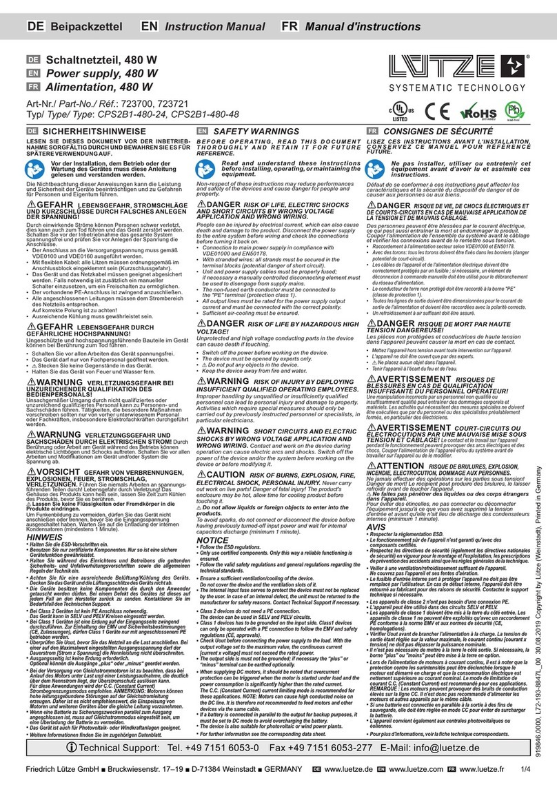
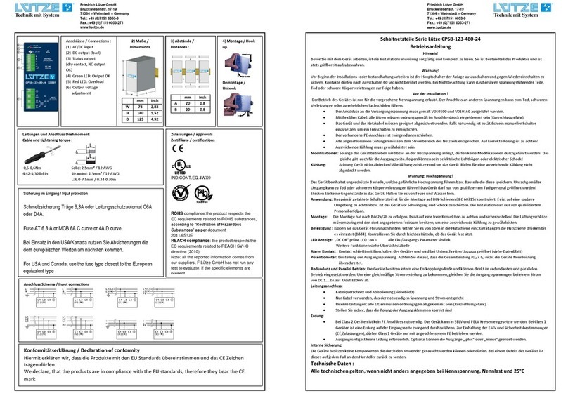
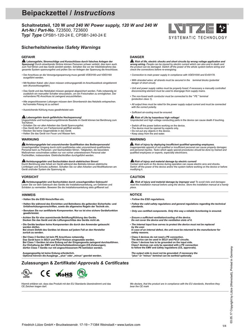
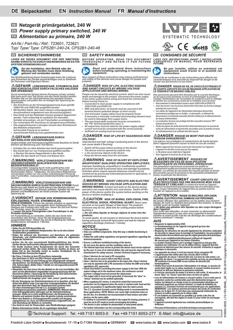
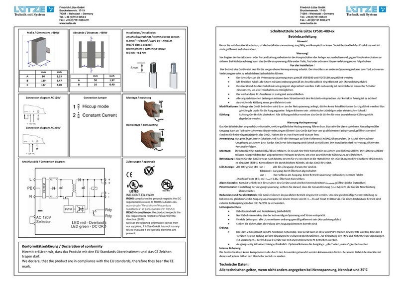
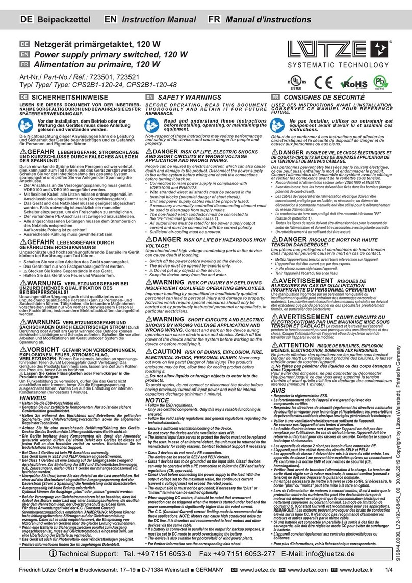
Lütze CPSB3-2400 Series User manual

Operating instructions
CPSB3-2400
High End Power Supply
Version 2.0

CPSB3-2400 - Operating instructions
2
The company Friedrich Lütze GmbH reserves the right to make changes to its products in the interest
of technical development. These changes are not necessarily documented in each individual case.
This manual and the information contained herein have been compiled with due care. However, the
company Friedrich Lütze GmbH accepts no liability for printing or other errors or resulting damage.
The brands and product names mentioned in this book are trademarks or registered trademarks of the
respective titleholders.
FRIEDRICH LÜTZE GMBH reserves the right to make changes without further notice to any products
herein. FRIEDRICH LÜTZE GMBH makes no warranty, representation or guarantee regarding the
suitability of its products for any particular purpose, nor does FRIEDRICH LÜTZE GMBH assume any
liability arising out of the application or use of any product, and specifically disclaims any and all
liability, including without limitation consequential or incidental damages. “Typical" parameters which
may be provided in FRIEDRICH LÜTZE GMBH data sheets and/or specifications can and do vary in
different applications and actual performance may vary overtime. All operating parameters, including
“Typicals", must be validated for each customer application by customer's technical experts.
FRIEDRICH LÜTZE GMBH does not convey any license under its patent rights nor the rights of
others. FRIEDRICH LÜTZE GMBH products are not designed, intended, or authorized for use as
components in systems intended for surgical implant into the body, or other applications intended to
support or sustain life, or for any other application in which the failure of the FRIEDRICH LÜTZE
GMBH product could create a situation where personal injury or death may occur. Should Buyer
purchase or use FRIEDRICH LÜTZE GMBH products for any such unintended or unauthorized
application, Buyer shall indemnity and hold FRIEDRICH LÜTZE GMBH and its officers, employees,
subsidiaries, affiliates, and distributors harmless against all claims, costs, damages, and expenses,
and reasonable attorney fees arising out of, directly or indirectly, any claim of personal injury or death
associated with such unintended or unauthorized use, even if such claim alleges that FRIEDRICH
LÜTZE GMBH was negligent regarding the design or manufacture of the part.
The Customer should ensure that it has the most up to date version of the document by contacting its
local FRIEDRICH LÜTZE GMBH office. This document supersedes any earlier documentation relating
to the products referred to herein. The information contained in this document is current at the date of
publication. It may subsequently be updated, revised or withdrawn.
The Customer should ensure that FRIEDRICH LÜTZE GMBH product uses the most up to date
Software and Firmware provided on FRIEDRICH LÜTZE GMBH website to ensure reliable operation
of the system.
All Trade Marks recognized. Specifications and information herein are Subject to change without
notice.
©Copyright 2021 by Friedrich Lütze GmbH. All rights reserved.
Contact
Friedrich Lütze GmbH
P.O.Box 1224 (PLZ 71366)
Bruckwiesenstraße 17-19
D-71384 Weinstadt - Großheppach
Germany
Phone: +49/ (0)7151 6053-0
Telefax: +49/ (0)7151 6053-277
Internet: www.luetze.com

CPSB3-2400 - Operating instructions
3
Content
1Introduction..................................................................................6
2General Information.....................................................................7
2.1 Symbol Description...........................................................................................7
2.2 Copyright...........................................................................................................7
2.3 Disclaim of Liability............................................................................................7
3Safety............................................................................................8
3.1 Content of the manual.......................................................................................8
3.2 Intended Use.....................................................................................................8
3.3 Recipients.........................................................................................................8
3.4 Operating Employees........................................................................................8
3.5 Responsibility of the operator............................................................................9
3.6 Protective Clothing and Equipment...................................................................9
3.7 Labelling............................................................................................................9
3.8 Reconstruction and Modifications of the Product............................................10
3.9 Safety Arrangement........................................................................................10
3.10 Special Safety Messages................................................................................10
4Scope of Delivery.......................................................................11
5Transportation and Storage ......................................................12
6Product Overview.......................................................................13
6.1 Product description .........................................................................................13
7Functional description...............................................................15
8Installing the CPSB3-2400.........................................................16
8.1 General considerations...................................................................................16
8.1.1 Input voltage .................................................................................................................... 16
8.1.2 Input protection devices................................................................................................... 16
8.1.3 Input connector wiring...................................................................................................... 16
8.1.4 Output connector wiring................................................................................................... 16
8.1.5Auxiliary connector wiring................................................................................................ 17
8.1.6 Cooling............................................................................................................................. 17
8.2 Mounting and dismounting the device.............................................................18
8.2.1 Mounting the device......................................................................................................... 18
8.2.2 Dismounting the device ................................................................................................... 18
8.3 Connecting the device.....................................................................................19
8.3.1 Standard connection........................................................................................................ 19
8.3.2 Connection with remote voltage sense............................................................................ 20
8.3.3 Connection in series ........................................................................................................ 21
8.3.4 Connection parallel (power and redundancy).................................................................. 22
8.3.5 Battery charger connection (only on “-24”, “-48” and “-72” models) ................................ 24
8.3.6 Output current remote measurement .............................................................................. 25
8.3.7 Remote shutdown input................................................................................................... 26

CPSB3-2400 - Operating instructions
4
8.3.8 Auxiliary 12V/100mA output ............................................................................................ 27
8.3.9 Auxiliary relay dry contacts.............................................................................................. 27
8.3.10 Connection to a PC through the USB communication box COMM BOX..................... 27
8.4 Maintenance ...................................................................................................28
9Operating modes........................................................................29
9.1.1 Overboost mode (default)................................................................................................ 29
9.2 Constant current limit mode............................................................................30
9.3Battery charger mode (available only on “-24”, “-48” and “-72” models) .........31
9.3.1 Lead acid and lithium iron phosphate (LiFePO4)............................................................ 31
9.3.1.1 Revival function....................................................................................................... 32
9.3.2 Nickel (NiCd, NiMH)......................................................................................................... 33
10 User interface.............................................................................34
10.1 Principles of operation.....................................................................................34
10.2 Contrast adjustment........................................................................................34
10.3 Initial and standard screens............................................................................35
10.3.1 Power ON test screen.................................................................................................. 35
10.3.2 ID screen...................................................................................................................... 35
10.3.3 Default screen.............................................................................................................. 36
10.4 Set-up menu ...................................................................................................36
10.4.1 Power limit.................................................................................................................... 37
10.4.2 Vin min alarm ............................................................................................................... 38
10.4.3 Vin max alarm .............................................................................................................. 38
10.4.4 Vout.............................................................................................................................. 38
10.4.5 Nominal lout ................................................................................................................. 38
10.4.6 Iout alarm threshold ..................................................................................................... 38
10.4.7 Date.............................................................................................................................. 39
10.4.8 Time ............................................................................................................................. 39
10.4.9 Remote shutdown polarity............................................................................................ 39
10.4.10 Temperature measurement unit................................................................................... 39
10.4.11 Enable buzzer .............................................................................................................. 39
10.4.12 Wiring........................................................................................................................... 39
10.4.13 Operating mode ........................................................................................................... 40
10.4.14 Battery type.................................................................................................................. 40
10.4.15 Battery nominal voltage (only for lead acid or LiFePO4 on “-24”, “-48”, and “72”
models) 40
10.4.16 Battery charge voltage (only for nickel on “-24”, “-48”, and “72” models) .................... 40
10.4.17 Battery capacity (only on “-24”, “-48”, and “72” models) .............................................. 40
10.4.18 Battery charge mode (only on “-24”, “-48”, and “72” models) ...................................... 41
10.4.19 Relay active on “DC OK”.............................................................................................. 41
10.4.20 Relay active on “Iout OK” ............................................................................................. 41
10.4.21 Relay active on “Temperature OK” .............................................................................. 41
10.4.22 Setting:......................................................................................................................... 41
10.4.23 Relay active on “AC OK” .............................................................................................. 41
10.4.24 Lock settings ................................................................................................................ 42
10.4.25 Product name............................................................................................................... 42
10.5 Measurements ................................................................................................42
10.5.1 Page 1.......................................................................................................................... 42
10.5.2 Page 2.......................................................................................................................... 42
10.5.3 Page 3.......................................................................................................................... 42
10.5.4 Page 4.......................................................................................................................... 42
10.5.5 Measurement accuracy................................................................................................ 43

CPSB3-2400 - Operating instructions
5
10.6 Event log.........................................................................................................43
10.6.1 Over Load error............................................................................................................ 44
10.6.2 Over Termperature error.............................................................................................. 44
10.6.3 Output Overvoltage error ............................................................................................. 44
10.6.4 Input Under Voltage error............................................................................................. 44
10.6.5 Input Over Voltage error............................................................................................... 45
10.6.6 PFC Under Voltage error ............................................................................................. 45
10.6.7 PFC Over Voltage error ............................................................................................... 45
10.6.8 DC/DC Converter Failure error .................................................................................... 45
10.6.9 Short Circuit error......................................................................................................... 45
10.6.10 Over Load alarm start .................................................................................................. 45
10.6.11 Over Load alarm end ................................................................................................... 46
10.6.12 Over Temperature alarm start...................................................................................... 46
10.6.13 Over Temperature alarm end....................................................................................... 46
10.6.14 Vin Under Voltage alarm start...................................................................................... 46
10.6.15 Vin Under Voltage alarm end....................................................................................... 46
10.6.16 Vin Over Voltage alarm start........................................................................................ 46
10.6.17 Vin Over Voltage alarm end......................................................................................... 46
10.6.18 Phase Loss alarm start ................................................................................................ 47
10.6.19 Phase Loss alarm end ................................................................................................. 47
10.6.20 Maintenance Due alarm start....................................................................................... 47
10.6.21 Maintenance Due alarm end........................................................................................ 47
10.6.22 Remote Shutdown event start...................................................................................... 47
10.6.23 Remote Shutdown event end....................................................................................... 47
10.6.24 Power On event ........................................................................................................... 47
10.6.25 Battery Charger Constant Current event ..................................................................... 48
10.6.26 Battery Charger Constant Voltage event ..................................................................... 48
10.6.27 Battery Charger Float event......................................................................................... 48
10.6.28 Battery Charger Error event......................................................................................... 48
10.6.29 Battery Charge Over Temperature event..................................................................... 48
10.7 Information......................................................................................................49
10.7.1 Model............................................................................................................................ 49
10.7.2 Serial Number .............................................................................................................. 49
10.7.3 Firmware ...................................................................................................................... 49
10.7.4 Date.............................................................................................................................. 49
10.7.5 Time ............................................................................................................................. 49
10.7.6 Mains event counter..................................................................................................... 49
10.7.7 Load event counter ...................................................................................................... 49
10.7.8 Environmental event counter ....................................................................................... 49
11 Service........................................................................................52
12 Revision of the Document.........................................................53
13 Acronyms ...................................................................................54

CPSB3-2400 - Operating instructions
6
1 Introduction
This manual is a component of the product:
2400 W High Efficiency Power Supply.
These instructions must be read and understood before installing,
operating, maintaining or dismantling the device.
It contains important information about the handling and safety.
Risk of injury and damage to equipment cause by non-observance of
the operating instructions.
The instructions contain important information on safety, commissioning,
operation, maintenance and disposal of the corresponding device.
Before installation or use, carefully read these instructions in order to rule out
possible dangers and damage and to guarantee correct use.
Always keep the document to hand.
This applies until the disposal of the product. When selling or lending, pass
the manual to the authorized person.
These operating instructions can also be found on the website of
Friedrich Lütze GmbH –www.luetze.com.
Search for either the article number, or the product name
“CPSB3-2400”.

CPSB3-2400 - Operating instructions
7
2 General Information
2.1 Symbol Description
The manual contains several safety messages. Each safety message contains a defined signal
word and a color. The color and the word are referring to an alert level. There are 4 levels. The
safety messages point out hazardous situations and give information to avoid those.
Indicates a hazardous situation, which if not avoided will result in death
or serious injury.
Indicates a hazardous situation, which if not avoided can result in death
or serious injury.
Indicates a hazardous situation, which if not avoided can result in minor
or moderate injury.
Indicates a situation which could damage the product or the
environment. This notice does not apply to personal injury.
2.2 Copyright
This manual is intended for the operator and his staff. It is forbidden to give the content to a third
party, to duplicate, exploit or impart it. The Friedrich Lütze GmbH has to allow it explicit in writing.
General data, text, images and drawings are copyrighted and are liable to the industrial property
right. Contravention can be prosecuting criminally. The named brands and product names in this
document are trademarks or registered trademarks by titleholder
2.3 Disclaim of Liability
The manual was written under consideration of the applied standards, regulations and the current
state of technology
The content is verified of accuracy. Discrepancies are not excluded. For those discrepancies we
disclaim liability. Applicable changes and additional information will be in the next version of the
manual.
•The Friedrich Lütze GmbH does not assume liability for any damages and accidents of
following reasons:
•Nonobservance of the manual
•Untrained and unqualified employees
•Non-conventional use
•Non approved reconstructions and functional modifications of the product
•Using non-original or non-admitted parts or equipment
•The real-time capability of the controller

CPSB3-2400 - Operating instructions
8
3 Safety
3.1 Content of the manual
Read and follow the manual before using the product the first time.
This applies to every person which is getting in touch with the product. Trained employees and
experts, especially qualified persons which had worked with similar products before, have to read
and understand the manual.
3.2 Intended Use
The intended use includes the procedure according to the operating instructions. The devices
may only be used for the cases specified in the technical documentation and only in connection
with the third-party equipment and components recommended or approved by us. The proper
and safe operation of the product requires proper transport, storage, installation and assembly,
as well as careful operation and maintenance.
3.3 Recipients
The operating manual addresses planers, project manager and programmers. It also addresses
the operating employees which are responsible for the initial operation, the operating and for the
maintenance of the products and systems. Regarding the employees different qualification levels
are differentiated.
3.4 Operating Employees
Risk of injury by deploying insufficient qualified operating employees.
Inappropriate use of not qualified or insufficient personal can cause property
damages and personal injuries. Tasks which apply special procedures should
be done by trained and qualified employees or experts, especially electrically
qualified persons.
The operating instructions are directed at the operator and the personnel with the
following areas of competence:
Work area
Competence
Installation
Qualified Electricians
Transport and Storage
Experts / Transport Personnel
Commissioning, Decommissioning
Experts
Operation
Trained staff / Users
Maintenance and Servicing
Experts / Service Personnel
Cleaning
Experts / Service Personnel
Troubleshooting
Experts
Trained Staff
The employee was trained by the employer on the task and possible hazardous situations. The
employee does not have any technical knowledge.

CPSB3-2400 - Operating instructions
9
Experts
The employee has a technical education, knowledge and/or experience in the required field. The
employee is capable to perform specific operations on and with the product.
Qualified electricians
The employee has a technical education in the required field. The employee is capable to
perform special operations on and with the product.
The different sections referring to the qualification level of the operating employees.
3.5 Responsibility of the operator
The operator is obligate by the law of occupational safety, if the product is used in a commercial
field.
•The operator is responsible to train the employees and to inform himself about the industrial
safety regulation.
•The operator is responsible that safety-, environment protection regulations and rules for
accident prevention are observed.
•The operator has to run a risk assessment at the working environment/place of installation to
expose hazards and to alert those.
•The manual has to be stored near the product.
•The manual has to be obeyed.
•The product can just be run in a faultless technical condition.
3.6 Protective Clothing and Equipment
If working with or on the PLC special ESD clothing and equipment is mandatory. Also follow the
instructions and regulations of the employer.
3.7 Labelling
Mind the original adhesive labels. Keep them readable.
On the product following label with following data can be found:
Fig. 1: Example Label
•Part-Number
•Hardware Revision
•Assembly Term

CPSB3-2400 - Operating instructions
10
•Software-Version
•Serial number
3.8 Reconstruction and Modifications of the Product
Reconstructions and modifications of the product can cause property
damages or personal injuries. Do not reconstruct the product if the
manufacturer does not allow it explicit in writing.
3.9 Safety Arrangement
Do not bypass protection equipment and safety arrangements. The
product can be damaged by overvoltage and electric shocks are possible.
3.10 Special Safety Messages
Use a nominal operating voltage of 24 Volts. The lower (16.8 Volts) and
upper (30 Volts) threshold voltage is given in the technical data. A higher
voltage can cause electric shocks and damage the product.
Dismount all electronic modules and their connections from the frame if
you intend to do some welding. The product can be damaged by
compensating current.

CPSB3-2400 - Operating instructions
11
4 Scope of Delivery
High end power supply CPSB3-2400-xx

CPSB3-2400 - Operating instructions
12
5 Transportation and Storage
Protect the devices from moisture. Store the device in dry rooms between
0°C (32 °F) and 60°C (140°F).
Make sure that the power supply is securely packed for transport. This
is the only way to absorb shocks.

CPSB3-2400 - Operating instructions
13
6 Product Overview
6.1 Product description
The CPSB3-2400x series is a high power, high performance, CPU controlled 3-phase input SMPS family.
These products present many advanced features such as:
▪Very high efficiency (>92%)
▪Compactness
▪PFC input
▪Operating also with DC input
▪Wide range of output voltage
▪Integrated active ORing circuit for all models
▪Increased input protection against various mains abnormalities (overvoltage, surge, micro-interruptions,
etc.)
▪Remote shutdown
▪Voltage sense function
▪4-20 mA and 0-10 V output current remote measurement
▪User programmable auxiliary dry contact
▪Load share (up to 4 units can be paralleled for redundancy or power increase)
▪3 operating modes:
oOverboost which can deliver up to 150% of the rated current for a maximum of 5 seconds
oConstant current
oLead-acid, LiFePO4 and NiCd/NiMH battery charger (only on “-24”, “-48” and “-72” models) with
temperature compensation for lead acid only
▪Microcontroller based for:
oMonitoring
oOperating control and supervision
▪User interface
oEmbedded user interface (4 user buttons, 2 LEDs and 1 LCD display):
▪Displays real time status and alarms
▪History of events, time stamped (a Real Time Clock is implemented)
oPC application through USB interface (using included COMM BOX interface):
▪Remote configuration of the device
▪Firmware upgrade
▪Same functionalities of the embedded user interface with the ease of the PC benefits
Use latest device Documentation, Software and Firmware to ensure reliable operation
of the system (downloadable from www.luetze.com).
The CPSB3-2400x family includes 4 models with 4 different output voltages and current ratings for a rated power
of 2400 W (peak overload power of 3600 W).
Model name
Rated Vout
[VDC]
Vout min [VDC]
Vout max [VDC]
Rated Iout /
Ipeak[A]
Rated / peak
power [W]
CPSB3-2400-24
24
11.5
29
100 / 150
2400 / 3600
CPSB3-2400-48
48
23
56
50 / 75
2400 / 3600
CPSB3-2400-72
72
50
87
33 / 50
2400 / 3600
CPSB3-2400-170
170
85
175
14 / 21
2400 / 3600
Table 1: Models rating

CPSB3-2400 - Operating instructions
14
.
Figure 1: Figure 1 shows a front view of the SMPS with a short description of the main elements
Figure 2: Auxiliary connector I/Os

CPSB3-2400 - Operating instructions
15
7 Functional description
A simplified block diagram of the CPSB3-2400 is shown in Figure 3.
Figure 3: CPSB3-2400 simplified block diagram
CPSB3-2400 is a 3-phase input SMPS with 2 power stages, supervised by a microcontroller. The first
stage is a power factor corrector (PFC) module that improves unit efficiency and reduces the harmonic
current from the mains. The second stage is a resonant full bridge converter that provides primary to
secondary insulation and high efficiency power conversion.
The product offers additional features that improve the performances and the reliability:
Integrated active ORing diode: allows connecting several devices in parallel for redundancy (see
§4.3.4). When several units are paralleled for increase of the total output power (up to 8.7kW) this
circuit increases the reliability of the system in case of 1 unit failure.
Load share functionality: allows connecting up to 4 devices in parallel to increase the output power
up to 8.7kW. A dedicated bus allows to equally share the total load current between the paralleled
devices.
Remote voltage sensing: allows regulating the output voltage directly at the load terminals
compensating the cables and connectors voltage drop when long cables are used.
Active surge protection: this circuit increases the reliability by protecting the device from high
voltage transients occasionally present on the 3 phase mains. On top of that this circuit performs also
the function of active inrush current limiter reducing the inrush current to very low values.
Smart thermal management: the fans’ speed is controlled according to load and internal temperature
conditions. This allows maintaining a safe temperature of the critical parts while maximizing the fans
operating life and minimizing the fans noise.
Remote output current measure: the user can measure remotely the output current delivered by the
SMPS. The information is provided through an opto-isolated output with 2 industry standard ranges:
0…10V or 4…20mA for 0A to rated output current.
Remote shutdown input: it allows to remotely switch the SMPS ON or OFF without cutting the 3
phase mains. An opto-isolated input can be configured as a remote shutdown/enable input
Auxiliary 12V output: the units provide a regulated 12V/0.1A output completely insulated from the
main output. It can be used to supply light 12V loads, independently on the SMPS output
voltage/status.
Battery charger mode (only on “-24”, “-48” and “-72” models): this operating mode allows
operating the device as a high performance battery charger for lead-acid, lithium iron phosphate
(LiFePo4) and NiCd/NiMH batteries. 12V, 24V, 48V, 60V and 72V batteries can be charged up to a
capacity of 1000Ah. Refer to Table 3 for the maximum battery capacity based on chemistry. The lead
acid and nickel batteries share the same capacities.

CPSB3-2400 - Operating instructions
16
8 Installing the CPSB3-2400
8.1 General considerations
CPSB3-2400 is a high voltage and high current SMPS. In order to avoid potentially
hazardous situations including fire hazard, safety recommendations must be followed.
Only authorized staff can install the unit.
8.1.1 Input voltage
Vin= 3x400…500VAC (range=340…550VAC) or 520…750VDC. Use with only 2 phases connection is prohibited.
Under emergency conditions only the units can operate with 2 phases input with reduced maximum power to ½
of the nominal.
Connect the Earth (PE) wire before connecting L1/L2/L3 wires and keep it as short as possible. The wire gauge
should be at least 1.5 mm2 (15 AWG).
8.1.2 Input protection devices
CPSB3-2400 is NOT equipped with an internal protection fuse. Use external breaking and protection devices as
circuit breakers rated 10A and characteristic C, properly rated for the operating voltage and with a minimum
breaking power of 1.5kA. Over- Current protection must be provided on each phase.
For USA and Canada use fuses class CC rated 10A. In some countries local regulation may apply.
Special ratings and devices should be used for DC input applications. Call factory for information.
Surge protection: it is strongly recommended to provide external surge arresters according to local regulations.
8.1.3 Input connector wiring
The input mains terminal block accepts wires up to 4mm2 (11AWG). Strip the wire insulation for 8mm, screw
tightening torque 0.5…0.6Nm, use only 60/75 Class 1 copper wires.
Before operating on the device disconnect the AC mains and wait at least 1 minute.
8.1.4 Output connector wiring
The output terminal block accepts wires up to 35mm2 (2AWG). Strip the wire insulation for 15mm, screw
tightening torque 2.5…4.5Nm, use only 60/75 Class 1 copper wires. Refer to Table 2 to define the minimum
wire gauge for each model.
Model name
Rated Vout [VDC]
Rated Iout [A]
Minimum wire gauge
[mm2 /AWG]
CPSB3-2400-24
24
100
25 / 3
CPSB3-2400-48
48
50
10 / 7
CPSB3-2400-72
72
33
6 / 9
CPSB3-2400-170
170
14
2.5 / 13
Table 2: Recommended output wire gauge

CPSB3-2400 - Operating instructions
17
8.1.5 Auxiliary connector wiring
The auxiliary terminal block accepts wires from 0.5mm2 (20AWG) to 1.5mm2 (15AWG). Strip the wire
insulation for 5mm, screw tightening 0.25Nm, use only 60/75 Class 1 copper wires.
8.1.6 Cooling
Mount the device in vertical position, keep at least 80mm (3inch) free spacing on upper and lower
side, 10mm (0.4inch) free spacing between adjacent devices. Check periodically that the air inlets in
the enclosure are free from dust and other debris that can obstruct the air flow.
Mount the device in the cooler zone of the cabinet. The thermal protection is activated if the
surrounding air temperature is >50°C (122 °F) along with continuous full load operation. The device
restarts automatically after cooling down.

CPSB3-2400 - Operating instructions
18
8.2 Mounting and dismounting the device
8.2.1 Mounting the device
Figure 4: Mounting the device on DIN rail
Snap on the device on IEC60715/H35-7.5 rail; push the bottom side of the device towards the rail. The
device will be automatically locked to the rail.
8.2.2 Dismounting the device
Figure 5: Dismounting the device on DIN rail
Pull down the slide using a screwdriver and then free the bottom part by rotating the device upwards.

CPSB3-2400 - Operating instructions
19
8.3 Connecting the device
8.3.1 Standard connection
Figure 6: Standard AC device connection

CPSB3-2400 - Operating instructions
20
Figure 7: Standard DC device connection
Check the polarity of the output load before applying mains.
8.3.2 Connection with remote voltage sense
Figure 8: Connection using remote voltage sense
This manual suits for next models
4
Table of contents
Other Lütze Power Supply manuals
Popular Power Supply manuals by other brands

Rockwell Automation
Rockwell Automation 1606-XLS960EE instruction manual

Pulsar
Pulsar PSB-754813 Technical description

daisalux
daisalux SBT-200 manual

POS
POS FTPC150V12-S-WP General Use Information

TAKASAGO
TAKASAGO HX-S-G4 Series instruction manual

Maynuo Electronic
Maynuo Electronic M88 Series user manual