manuals.online logo
Brands
  1. Home
  2. •
  3. Brands
  4. •
  5. Lütze
  6. •
  7. Power Supply
  8. •
  9. Lütze CPSB1-120-24 E User manual

Lütze CPSB1-120-24 E User manual

Beipackzettel / Instructions
Friedrich Lütze GmbH ▪ Bruckwiesenstr. 17-19 ▪ 71384 Weinstadt ▪ www.luetze.com
03.05.17 Copyright by Lütze (Weinstadt), Printed in Germany
1/4
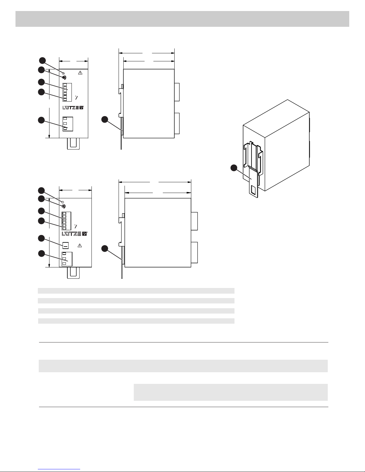
Schaltnetzteil, 120 W und 240 W/ Power supply, 120 W and 240 W
Art-Nr./ Part-No. 723500, 723600
Typ/ Type CPSB1-120-24 E, CPSB1-240-24 E
Verletzungsgefahr und Sachschäden durch elektrischen Strom!
Durch Berührung oder Arbeit am Gerät während des Betriebs können elektrische
Lichtbögen und Schocks auftreten. Schalten Sie vor allen Arbeiten und Modifikationen am
Gerät und/oder System die Spannung ab.
Risk of injury and material damage by electric current!
Contact and work on the device during operation can cause electric arcs and shocks.
Switch off the power of the device and/or the system before working on the device or before
modifying it.
Sicherheitshinweise /Safety Warnings
▪ Benutzen Sie nur zertifizierte Komponenten. Nur so ist eine sichere Gerätefunktion
gewährleistet.
▪ Halten Sie während des Einrichten und Betreibens die geltenden Sicherheits- und
Unfallverhütungsvorschriften, sowie die allgemeine Regeln der Technik ein.
▪ Halten Sie die ESD-Vorschriften ein.
▪ Follow the valid safety regulations and general regulations regarding the technical
standards.
▪ Follow the ESD regulations.
▪ Only use certified components. Only this way a reliable functioning is ensured.
HINWEIS
WARNUNG
VORSICHT
WARNING
CAUTION
NOTICE
i
Zulassungen & Zertifikate/ Approvals & Certificates
Hiermit erklären wir, dass das Produkt mit den EU Standards übereinstimmt und das
CE Zeichen tragen darf.
Risk of injury by deploying insufficient qualified operating employees.
Inapproperiate appoint of not qualified or insufficient personal can cause property damages
and personal injuries. Tasks which apply special procedures should be done by trained and
qualified employees or experts, especially electricians.
GEFAHR DANGER
Risk of life, electric shocks and short circuits by wrong voltage application and
wrong wiring. People can be injured by electric current which can also end in death and
the product can be damaged. Switch off the power of the whole system before wiring and
check the connections before re-energizing.
▪ Connection to main power supply in compliance with VDE01000 and En50178.
▪ With stranded wires: all strands must be secured in the terminal blocks (potential
danger of short circuit).
▪ Unit and power supply cables must be properly fused; if necessary a manually controlled
disconnecting element must be used to disengage from supply mains.
▪ The non-fused earth conductor must be connected to the " PE " terminal
(protection class 1).
▪ All output lines must be rated for the power supply output current and must be connected
with the correct polarity.
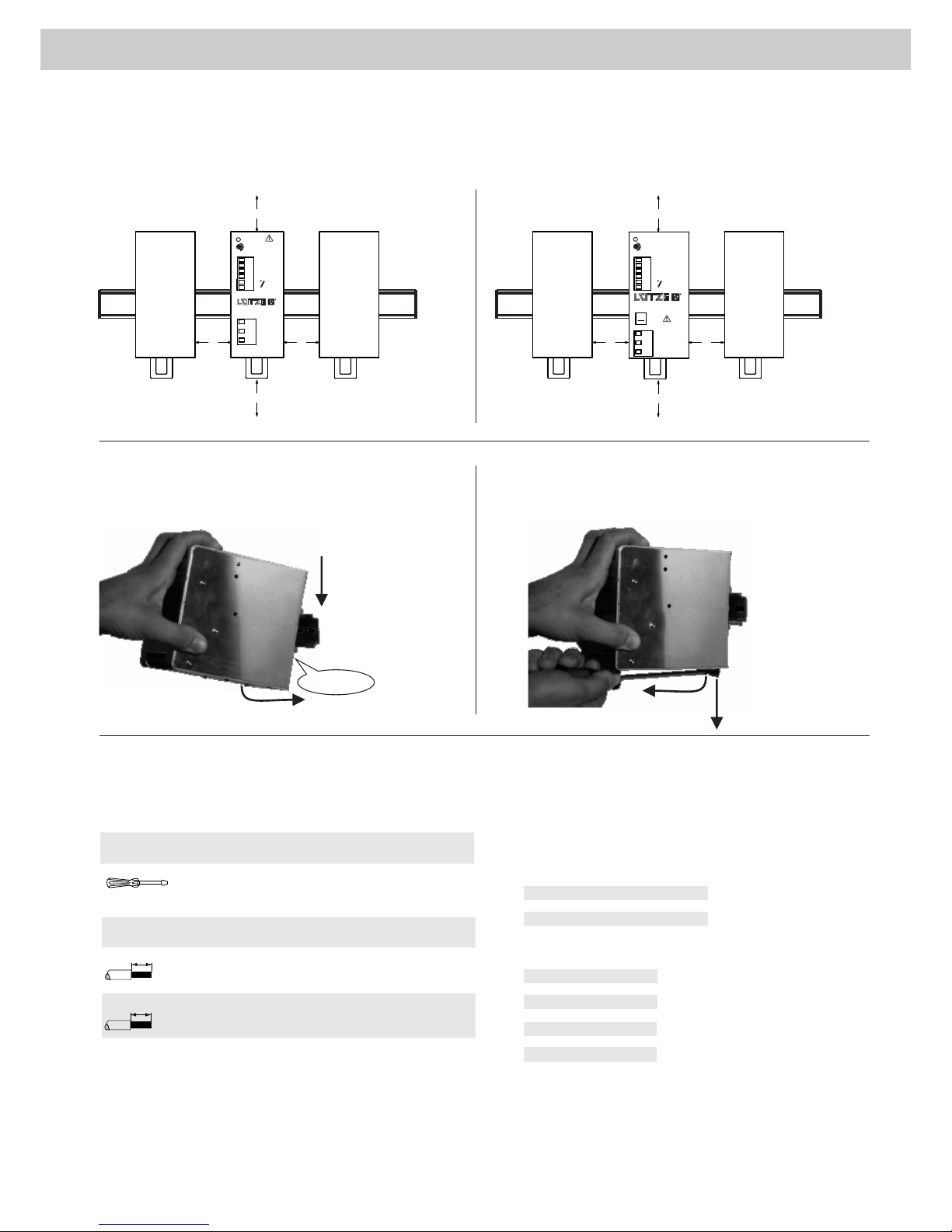
▪ Sufficient air-cooling must be ensured.
Verletzungsgefahr und Sachschäden durch unsachgemäßen Gebrauch!
Lesen Sie vor dem Gebrauch des Geräts die Installationsanleitung, um Gefahren und
Schäden zu vermeiden. Bewaren Sie die Installationsanleitung stets griffbereit auf.
Risk of injury and material damage by improper use! To avoid risks and damages
read the installation manual before using the device. Store the installation manual at a handy
place.
Lebensgefahr, Stromschläge und Kurzschlüsse durch falsches Anlegen der
Spannung! Durch einwirkende Ströme können Personen schwer verletzt, dies kann auch
zum Tod führen und das Gerät zerstört werden. Schalten Sie vor der Inbetriebnahme das
gesamte System spannungsfrei und prüfen Sie vor Anlegen der Spannung die Anschlüsse.
▪ Der Anschluss an die Versorgungsspannung muss gemäß VDE0100 und VDE0160
ausgeführt werden.
▪ Mit flexiblen Kabel: alle Litzen müssen ordnungsgemäß im Anschlussblock eingeklemmt
sein (Kurzschlussgefahr).
▪ Das Gerät und das Netzkabel müssen geeignet abgesichert werden. Falls notwendig ist
zusätzlich ein manueller Schalter einzusetzen, um ein Freischalten zu ermöglichen. Der
vorhandene PE-Anschluss ist zwingend anzuschließen.
▪ Alle angeschlossenen Leitungen müssen dem Strombereich des Netzteils entsprechen.
Auf korrekte Polung ist zu achten!
▪ Ausreichende Kühlung muss gewährleistet sein
Verletzungsgefahr bei unzureichender Qualifikation des Bedienpersonals!
Unsachgemäßer Umgang durch nicht qualifiziertes oder unzureichend qualifiziertes
Personal kann zu Personen- und Sachschäden führen. Tätigkeiten, die besondere
Maßnahmen vorschreiben sollten nur von vorher unterwiesenem Personal oder
Fachkräften, insbesondere Elektrofachkräften durchgeführt werden.
We declare, that the product are in compliance with the EU standards, therefore they
bear the CE mark
▪ Class 2 devices do not need a PE connection.
The device can be used in SELV and PELV circuits.
Class 1 devices has to be grounded on the input side.
Class1 devices can only be operated with a PE connection
to follow the EMV and safety regulations (CE, approvals).
The output side is must not be grounded; if necessary the
“plus” or “minus” terminal can be earthed optionally.
▪ Ensure a sufficient ventilation/cooling of the device.
Do not cover the device and the ventilation slots of it.
▪ The internal input fuse serves to protect the device must not be replaced
by the user.
In case of an internal defect, the unit must be returned to the manufacturer for
safety reasons.
▪ Achten Sie für eine ausreichende Belüftung/Kühlung des Geräts.
Decken Sie das Gerät und die Lüftungsschlitze des Geräts nicht ab.
▪ Die Geräte besitzen keine Komponenten die durch den Anwender getauscht
werden dürfen.
Bei einem Defekt des Gerätes ist dieses auf jedem Fall an den Hersteller
zurück zu senden.
▪ Bei Class 2 Geräten ist kein PE Anschluss notwendig.
Das Gerät kann in SELV und PELV Kreisen eingesetzte werden.
Bei Class 1 Geräten ist eine Erdung auf der Eingangsseite zwingend durchzuführen.
Zur Einhaltung der EMV und Sicherheitsbestimmungen (CE,Zulasungen),
dürfen Class 1 Geräte nur mit angeschlossenem PE betrieben werden.
Ausgangsseitig ist keine Erdung erforderlich.
Optional können die Ausgänge „ plus“ oder „minus“ geerdet werden.
Risk of Life by hazardous high voltage!
Unprotected and high voltage conducting parts in the device can cause death if touching.
▪ Switch off the power before working on the device.
▪ The device must be opened by experts only.
▪ Do not put any objects in the device.
▪ Keep away from fire and water.
Lebensgefahr durch gefährliche Hochspannung!
Ungeschützte und hochspannungsführende Bauteile im Gerät können bei Berührung zum
Tod führen.
▪ Schalten Sie vor allen Arbeiten das Gerät Spannungsfrei.
▪ Das Gerät darf nur von Fachpersonal geöffnet werden.
▪ Stecken Sie keine Gegenstände in das Gerät.
▪ Halten Sie das Gerät von Feuer und Wasser fern.
Beipackzettel / Instructions
www.luetze.com
2/4
LED Status / LED Status
Potentiometer
Einstellung der Ausgangsspannung.
Die Gesamtleistung (UA x IA) darf nicht die Geräte Nennleistung
überschreiten.
Setting of the output voltage.
The total power (UA x IA) must not exceed the nominal power.
Produktaufbau / Product Assembly
+
+
-
-
OUTPUT
DC OK
24VDC/20A
23...28V
INPUT
120-240VAC
4.8–2.4A
50-60Hz
1
3
4
6
7
7
1
2
3
4
e
6
i
IND.CONT:EQ.
4WX9
5
7
110
40
115
4
4
L
N
1
2
3
0
–
–
DC OK
24V/1A
CPSB-1-120-24 E
723500
2
Farbe
Color
Status
Status
LED
LED
Beschreibung
Description
grün/ green
an/ on
aus/ off
DC OK Alle Funktionen und IN/OUT Parameter sind in Ordnung
All functions and IN/OUT parameter are OK
Kurzschluss am Ausgang, keine Betriebsspannung,
interner Fehler
Short Circuit on the output, not power supply, internal error
1 X1: AC/DC Eingang/ AC/DC Input
2 X2: Diagnose Ausgang (Relaiskontakt Schließer) / Diagnostic output (relay contact NO)
3 X2: DC Ausgang (Last)/ DC output (load)
4 Abgleich Ausgangsspannung/ Output voltage adjustment
5 Grüne LED: Ausgang OK/ Green LED: Output OK
6 Auswahl Eingangsspannung/ Input voltage selection
7 Hutschienenaufrastung/ DIN rail mounting
CPSB-1-240-24 E
723600
3
4
7
127
63
140
4
723600
CPSB1-240-24 E
5
+
+
-
-
OUTPUT
DC OK
24VDC/20A
23...28V
INPUT
120-240VAC
4.8–2.4A
50-60Hz
1
2
3
4
e
6
i
IND.CONT:EQ.
4WX9
L
N
1
2
3
0
–
–
DC OK
24V/1A
5
120V
240V
1
3
4
5
4
4
2
6
723500
CPSB1-120-24 E 120
117
Beipackzettel / Instructions
www.luetze.com
3/4
2
20 20
50
50
CPSB-1-240-24 E
723600
+
+
-
-
OUTPUT
DC OK
24VDC/20A
23...28V
INPUT
120-240VAC
4.8–2.4A
50-60Hz
1
2
3
4
e
6
i
IND.CONT:EQ.
4WX9
L
N
1
2
3
0
–
–
DC OK
24V/1A
5
120V
240V
Verdrahtung/ Wiring
HINWEIS Verwenden Sie nur Kupferkabel, die der notwendigen Spannung und Strom entspricht
NOTICE Use only copper cables which are designed for the indicated voltage and current values.
Pinbelegung/ Pin Assignment
Montage/ Mounting Demontage/ Demounting
2
1PUSH
PULL
1
CLACK
Installation/ Installation
HINWEIS Halten Sie folgende Montageabstände ein, um eine
ordnungsgemäße Belüftung zu gewährleisten:
NOTICE Mind the following mounting distances for a good ventilation:
▪ Montage auf DIN –Tragschiene nach EN 60715./
Mounting on DIN hat rail according EN 60715.
▪ Einbaulage/Installation position: horizontal/horizontal
723600
CPSB1-240-24 E
723500
CPSB1-120-24 E
+
+
-
-
OUTPUT
DC OK
24VDC/20A
23...28V
INPUT
120-240VAC
4.8–2.4A
50-60Hz
1
2
3
4
e
6
i
IND.CONT:EQ.
4WX9
L
N
1
2
3
0
–
–
DC OK
24V/1A
CPSB-1-120-24 E
723500
5
eindrähtig
solid
0,2 – 2,5 mm²
AWG 12 – 24
0,2 – 2,5 mm²
AWG 12 – 24
Abisolierlänge
Stripping Length
6mehrdrähtig
fine stranded
6
Querschnitt
Conductor Size
0,5 – 0,6 Nm
4,42 – 5,30 lb in
3,0 x 0,5 mm
Schraubendreher
Screwdriver
Anzugsdrehmoment
Tightening Torque
X1: AC/DC Eingang/ AC/DC Input
X2: DC Ausgang/ DC Output
Pin/ Pin Signal/ Signal
1 PE
2 N = Neutral
3 L = Line
Pin/ Pin Signal/ Signal
1 +
2 +
3 -
4 -
5 DC OK 24V/1A
6 DC OK 24V/1A
20 20
50
50
Beipackzettel / Instructions
www.luetze.com
4/4
(1) Sicherung ist nicht austauschbar; fuse is not replaceable
Allgemein : Alle angegebenen Daten sind typisch und wenn nicht anders vermerkt gültig bei 230 V am Eingang und einer Umgebungs-temperatur von 25 °C.
General : all specified datas are typical and unless otherwise specified measured at 230 V input and 25 °C environmental temperature.
Technische Daten/ Technical Data
Betrieb/ Operation
Redundanz und Parallel Betrieb Redundancy and parallel operation
Alarm Kontakt Alarm Contact
The devices do not internally have a decoupling diod and can only be
used to increase the power in parallel operation. To obtain an even
distributation of electricity, match the output voltage at a current of
DC 1..2A to Uout ±100mV.
An additional redudanz modul or diode is to be used for a redudanz
operation.
Die Geräte besitzen intern keine Entkopplungsdiode und
können nur zur Leistungserhöhung im Parallelbetrieb ein-
gesetzt werden. Um eine gleichmäßige Stromverteilung
zu erhalten, gleichen Sie die Ausgangsspannung bei ein-
em Strom von DC 1..2A auf Uout ±100mV ab.
Für einen Redudanzbetrieb ist ein zusätzliches Redudanz-
modul oder Dioden zu verwenden.
Kontakt schließt mit Einschalten des Gerätes und wird bei
Unterschreiten Uthreshold geöffnet (siehe Datenblatt).
Contact is switched on with power on and open when
Uout ≤ Uthreshold (see data sheet)
Typ/ Type
Artikelnummer/ Part-No.
CPSB1-120-24 E
723500
CPSB1-240-24 E
723600
Eingang / Input
Eingangsspannungsbereich
Input voltage range
AC 120V – AC240V
(AC 90V-264V / DC110-345V)
120/240V (AC90V-132V)
AC187V-AC264V / DC270V-DC345V)
Frequenz / frequency
47 Hz – 63Hz
Eingangsstrom @ Un
Input current @ Un
AC 2,1A @ AC 120V +/-10%
AC 1,2A @ AC 240V +/-10%
AC 4A @ AC 120V +/-10%
AC 2A @ AC 240V +/-10%
Einschaltstrom
Inrush current
< AC 40A
< AC 40A
PFC > 0,6 @ Vollast / Full load
Interne Sicherung1; Internal fuse1
T 3,15A
T 6,3A
Ext. Eingangssicherung
External protection on ac line
Automat / Circuit breaker: C; 6A
Schmelzsicherung / Fuse: T 6A
Automat / Circuit breaker: C; 10A
Schmelzsicherung / Fuse: T 10A
Ausgang / Output
Nennspannung Ausgang
Nominal output voltage
DC 24V
(DC 23V-DC28V)
DC 24V
(DC 23V-DC28V)
Max. Ausgangsstrom @ AC 240V
Max. output current @ AC 240V
DC 7,0A
DC 13,5A, 30sec.
Nennstrom Ausgang
Nominal output current
DC 5A DC 10A
Lastregelung / Load regulation
< 1%
Ripple @ Imax < 60mV pp < 100mV pp
Netzausfallüberbrückung
Hold up time @ full load
> 50ms @ AC 240V
> 20ms @ AC 120V
>60ms@AC 120V
> 70ms@AC 240V
Überlast / Kurzschlußschutz
Overload / Short circuit protection
HICCUP,over temp. protection; overvoltage : >DC33V(UA=24V)
Übertemperatursicherung
Over temperature protection
Ja / Yes
Überspannungssicherung
Output voltage protection
>DC 33V >DC 33V
Relais (Alarm Ausgang)
Relays (alarm output)
1 Schließer, 1 NO; DC 24 V, 1 A
Status Anzeige (DC ON)
Status indication (DC ON)
JA / Yes
Parallel Betrieb
Parallel operation
Possible for redundancy with external ORing devices
Allgemeine Daten / General data
Effektivität
Efficiency
>87%
>88%
Betriebstemperatur
Operation temperature
-40°/+70°C (UL certified up to 60°C)
Derating
>60°C: -2,4W/°C
>60°C: -5,0W/°C
Verlustleistung / Dissipated power <18W < 33W
Isolationsspannung / Isolation voltage
Input/Output:DC 4,2kV/1min; Input/Ground: DC2,2kV/1min; Output/Ground: 0,75kV/1min
Schutzart / IP rating IP20
Verschmutzungsgard / Pollution degree
2 (IEC60664-1)
Gehäusematerial / Housing material Aluminium
Gewicht / Weight
450g
750g
Anschlusstechnik / Termination Schraubanschluss / Screw terminal 2,5mm2
Montage / Mounting
TS 35 acc. IEC 60715
MTBF -
Standards / Standards
UL 508, EN 60950, EN 50178, EN55011 Class A; EN 55022 Class B; EN 61000-4-2,3,4,5,11; EN60529,
IEC60068-2-6,27

This manual suits for next models

1

Other Lütze Power Supply manuals

Lütze CPSB1-480-24E User manual

Lütze

Lütze CPSB1-480-24E User manual

Lütze CPSB3-2400 Series User manual

Lütze

Lütze CPSB3-2400 Series User manual

Lütze CPS2B1-240-24 User manual

Lütze

Lütze CPS2B1-240-24 User manual

Lütze CPSB1-480 Series User manual

Lütze

Lütze CPSB1-480 Series User manual

Lütze CPS2B1-480-24 User manual

Lütze

Lütze CPS2B1-480-24 User manual

Lütze CPSB-123-480-24 User manual

Lütze

Lütze CPSB-123-480-24 User manual

Lütze CPSF1-40-24 User manual

Lütze

Lütze CPSF1-40-24 User manual

Lütze CPS2B1-120-24 User manual

Lütze

Lütze CPS2B1-120-24 User manual

Popular Power Supply manuals by other brands

Kinco PS Series Installation instruction

Kinco

Kinco PS Series Installation instruction

Placid Industries PS-12-MC instruction manual

Placid Industries

Placid Industries PS-12-MC instruction manual

Electrosec DPS-3 user guide

Electrosec

Electrosec DPS-3 user guide

Rockwell Automation 1606-XLS480 instruction manual

Rockwell Automation

Rockwell Automation 1606-XLS480 instruction manual

Scientific PS3200 Series user manual

Scientific

Scientific PS3200 Series user manual

Hochiki America FN-400ULX installation guide

Hochiki America

Hochiki America FN-400ULX installation guide

Pulsar R1612T quick start guide

Pulsar

Pulsar R1612T quick start guide

Cosel KHEA30F instruction manual

Cosel

Cosel KHEA30F instruction manual

NGI N39200 Series user manual

NGI

NGI N39200 Series user manual

Ultra Products V-Series Specification sheet

Ultra Products

Ultra Products V-Series Specification sheet

JVA Wi-Fi Anywhere PTE2704 quick start guide

JVA

JVA Wi-Fi Anywhere PTE2704 quick start guide

Gallagher 3E3446 M5800i instructions

Gallagher

Gallagher 3E3446 M5800i instructions

Kemot URZ3424 owner's manual

Kemot

Kemot URZ3424 owner's manual

RTZ Legends 500 PS410 owner's manual

RTZ

RTZ Legends 500 PS410 owner's manual

Altronix Isolated Series installation guide

Altronix

Altronix Isolated Series installation guide

Puls PIANO Series manual

Puls

Puls PIANO Series manual

VOLTCRAFT DSP-3005 operating instructions

VOLTCRAFT

VOLTCRAFT DSP-3005 operating instructions

Altronix AL400ULX installation guide

Altronix

Altronix AL400ULX installation guide

manuals.online logo
manuals.online logoBrands
  • About & Mission
  • Contact us
  • Privacy Policy
  • Terms and Conditions

Copyright 2025 Manuals.Online. All Rights Reserved.