La Cornue Grand-Maman 90 User manual

1
Dear Customer,
Thank you for purchasing a La Cornue cooker. We hope that you will really enjoy
preparing delicious meals with it.
The aim of this installation guide is to familiarise you with the potential of a
professional quality appliance designed for domestic use and to facilitate its upkeep.
Above all, a La Cornue cooker is manufactured from noble and pure materials. The
specific choices for certain components, such as brass for the burners and cast-iron for
the hotplate, correspond to technicality and professional performance requirements
which are not attainable with other materials or protective treatments. We are very
much attached to the authenticity of our cookers and we are convinced that you will
appreciate them even more as you use them.
We recommend you follow the advice provided in the “Instructions for Use” brochure;
this will ensure that you are satisfied with your cooker for a long time.
Thank you for placing your trust in us.
Xavier Dupuy
President and Managing Director

2
©2007 - LA CORNUE – Installation Guide for Europe - “Cornuchef” Range.
Novemeber 2007 - A.K.

3
Installation Guide - “Cornuchef” Range
WARNING
This appliance must be installed by a qualified professional in accordance with the
current regulations in the country where the appliance is installed and must only be
used in a well ventilated area. Read the guides before installing and using this
appliance.
Appliance categories (see pt. 1.2, page 14 “Installation”):
- Class 1: Free-standing cooking appliance not normally in direct contact with the kitchen
units or the surrounding walls.
-Class 2: Cooking appliance that can be integrated between two kitchen units, whose walls
can be in direct contact with the surrounding units. This type of appliance can be in
contact with only one kitchen unit during installation.
- Class 2 / Sub-Class 1: Class 2 appliance that can be free-standing or installed so that the
side panels are accessible.
Before installing the appliance, ensure that the local gas supply conditions (gas type and
pressure) and the adjustment of the appliance are compatible.
The adjustment conditions for this appliance are indicated on the label at the back of the
hob and on the test certificate.
This appliance is not intended to be connected to a ventilation system or a ventilation shaft
for combustion products. It should be installed and connected in accordance with the
current regulations, and special attention should be paid to the applicable ventilation
regulations.
The use of a gas cooking appliance results in the production of heat and moisture in the
room where it is installed. Ensure that the room is well ventilated: keep natural ventilation
holes open or install a mechanical ventilation device (mechanical extractor hood).
Prolonged or intensive use of the appliance may call for additional ventilation, e.g. by
opening a window, or for more effective ventilation, by increasing the power of the
mechanical ventilation system installed.
The parts that are protected by the manufacturer must not be manipulated by the installer
or the user.
Please note:
The accessible parts may be hot when the oven is being used: keep young children at a safe
distance.
All of our cooking appliance belong to Class 1 and Class 2 / Sub-Class 1 and are designed for domestic use
only. They meet the requirements of the 90/396/CEE European Directive (“Gas Appliances”) and the
72/73/CEE European Directive (“Low Voltage Directive”), both amended by the 93/68/CEE Directive.

4Installation Guide - “Cornuchef” Range
WARNING ..................................................................................................... 3
DESCRIPTION ............................................................................................... 5
1. General description ................................................................................... 5
2. Hob configurations .................................................................................... 6
3. Energy power and gas flow rates .............................................................. 7
4. Power ratings for the electrical elements ............................................... 7
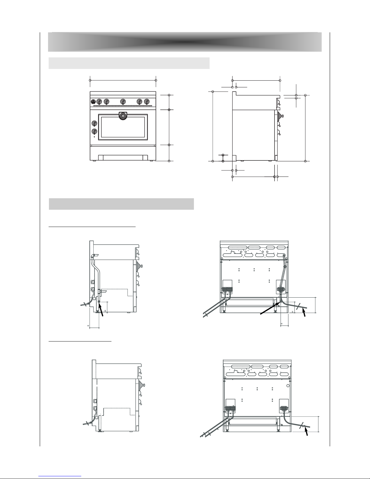
COOKER “GRAND - MAMAN 90” ................................................................. 8
1. Dimensions ................................................................................................. 8
2. Connections ................................................................................................ 8
3. Energy power ............................................................................................. 9
COOKER “GRAND - PAPA 135” .................................................................... 10
1. Dimensions ................................................................................................10
2. Connections .............................................................................................. 10
3. Energy power ............................................................................................ 11
HOBS ............................................................................................................ 12
1. Dimensions hob “Grand-Maman 90” ....................................................... 12
2. Connections hob “Grand-Maman 90” ....................................................... 12
3. Dimensions hob “Grand-Papa 135” .......................................................... 12
4. Connections hob “Grand-Papa 135” ......................................................... 13
5. Energy power hobs “Grand-Maman 90” and “Grand-Papa 135” .............13
BEFORE DELIVERY ..................................................................................... 14
1. Safety requirements ................................................................................. 14
2. Electrical supply ....................................................................................... 15
3. Gas supply ................................................................................................ 16
4. Installation ............................................................................................... 16
CONNECTIONS ............................................................................................ 17
1. Electrical connections .............................................................................. 17
2. Gas connection ........................................................................................ 18
IGNITION - ADJUSTMENTS ........................................................................ 19
1. Starting the appliance .............................................................................. 19
2. Replacing the oven light .......................................................................... 23
3. Changing the injectors ............................................................................. 24
4. Adjusting the low settings ........................................................................25
5. Injectors table ........................................................................................... 26
WARRANTY ................................................................................................. 27
CONTENTS

5
Installation Guide - “Cornuchef” Range
DESCRIPTION General description
DESCRIPTION
1. GENERAL DESCRIPTION
The range of "CORNUCHEF" cooking appliances consists of 4 models:
- Cooker “Grand-Maman 90” (model GM2, width: 90cm).
- Cooker “Grand-Papa 135” (model GP2, width: 135cm).
- Hob “Grand-Maman 90” (model TM2, width: 90cm).
- Hob “Grand-Papa 135” (model TP2, width: 135cm).
Each of the cooker or hot top models includes several sub-models, depending on the cho-
sen hot top and its combination with the oven.
The cookers in the "CORNUCHEF" range consist of:
- a thermostatically-controlled electric or gas oven;
- one hot top bounded at the rear by a stainless steel skirting creating a gap between the
cooker and the wall, thus ensuring the removal of burnt gases and smells.
The "Grand-Papa" stove is equipped with a 45 cm wide electric steam oven, located to the
right of the oven, which is used to warm plates.

DESCRIPTION
6Installation Guide - “Cornuchef” Range
Hob configurations
2. HOB CONFIGURATIONS
2 gas burners (small burner at the rear)
1 single gas burner
2 gas burners
2 gas burners (small burner at the rear)
1 gas hotplate
2 gas burners
2 gas burners (small burner at the rear)
1 single gas burner
2 electric ceramic plates
2 gas burners (small burner at the rear)
1 single gas burner
2 electric induction plates
2 gas burners (small burner at the rear)
1 gas hotplate
2 electric ceramic plates
2 gas burners (small burner at the rear)
1 gas hotplate
2 electric induction plates
2 electric ceramic plates
1 electric hotplate
2 electric ceramic plates
2 electric induction plates
1 electric hotplate
2 electric induction plates
123
124
2 gas burners (small burner at the rear)
1 single gas burner
1 small electric teppan-yaki
120
174
129
173
179
989
484
ALL GAS
MIXED (GAS AND ELECTRIC)
ALL ELECTRIC
2 electric ceramic plates
1 small electric teppan-yaki
2 electric ceramic plates
2 electric induction plates
1 small electric teppan-yaki
2 electric induction plates
909
404
ALL ELECTRIC WITH TEPPAN-YAKI

7
Installation Guide - “Cornuchef” Range
DESCRIPTION Energy power
All of our appliances belong to Category II and are designed for gases from the second and
third groups.
The gas used can be either natural gas, propane or butane, depending on availability. Refer
to pages 24 – 26 for information about adapting your cooker or your hob to the various
types of gas.
The tables below summarise for each gas type and for each burner the heat flow rate
(energy power in kW, Maximum Heat Power) and the volume flow rate (in m3/hour) or
the mass flow rate (in kg/hour) of useful gas.
Large vaulted electric oven (74/84 litres, large volume) ......................................... 6 000 W
3 500 W oven floor + 2 500 W vault
Grill in large vaulted gas oven ..............................................................................… 2 500 W
Baking stone ............................................................................................................ 3 000 W
Oven light ..................................................................................................................... 25 W
Ignition for small and large vaulted gas ovens .............................................................. 25 W
Automatic ignition for gas burners ............................................................................... 25 W
Warming cupboard, width: 450 mm ....................................................................… 1 750 W
Electric ceramic hob, Ø 145 mm .............................................................................. 1 200 W
Electric ceramic hob, Ø 195 mm (2 zones) .............................................................. 1 800 W
Round electric plate, Ø 180 mm .............................................................................. 2 000 W
Round electric plate, Ø 220 mm .............................................................................. 2 000 W
Electric hotplate ..........……………………………..................................................... 1 300 W
(small, dimensions: 284 x 476 mm)
Small “La Cornue” Teppan-Yaki .................................................….......................... 1 600 W
Induction plates (2 burners) ................................................................................… 3 600 W
3. ENERGY POWER AND GAS FLOW RATES
4. POWER RATINGS FOR THE ELECTRICAL ELEMENTS
Burner
Nominal heat
flow
Volume flow rate (m 3 / hour)
Mass flow rate (kg / hour)
(Maximum
Heat Power in
kW)
Natural Gas
G20, 20 mbar
Natural Gas
G25 20 mbar
Propane
G31 37 mbar
Butane
G30 29 mbar
Gas hobs:
- large burner
- small burner
3
1,7
0,29
0,16
0,33
0,19
0,21
0,12
0,22
0,12
Hotplate
3
0,29
0,33
0,21
0,22
Large vaulted gas oven
(74/84 l)
6,5
0,62
0,72
0,46
0,47

8Installation Guide - “Cornuchef” Range
Dimensions, connections GRAND-MAMAN 90
Mixed gas/electric cooker
All-electric cooker
2. COOKER CONNECTIONS
GRAND - MAMAN 90
220 480 200
900
950
80
575 40
50
900
40
50
650
140
140
200
200
100
100
125
125
140
140
Rear view
200
200
Rear view
CABLE 2
CABLE 1
CABLE 1
1. COOKER DIMENSIONS
TERMINAL
BLOCK 1
TERMINAL
BLOCK 2
CABLE 2 & 3
TERMINAL
BLOCK 1
TERMINAL
BLOCK 2 & 3
GAS INLET
MALE G 1/2 CONNECTION
GAS INLET
MALE G 1/2 CONNECTION
Cooker weight: 110 - 150 kg. depending on the model

9
Installation Guide - “Cornuchef” Range
GRAND-MAMAN 90 Gas and electric Power
GRAND - MAMAN 90
3. POWER FOR GAS AND ELECTRIC COOKERS

10 Installation Guide - “Cornuchef” Range
Dimensions, connections GRAND-PAPA 135
Mixed gas/electric cooker
All-electric cooker
2. COOKER CONNECTIONS
GRAND - PAPA 135
1350
480
200
220
Cooker weight: 180 - 220 kg. depending on the model
950
80
575 40
50
900
40
50
650
140
140
200
200
100
100
125
125
140
140
Rear view
200
200
Rear view
CABLE 2 CABLE 1
CABLE 1
GAS INLET
MALE G 1/2
CONNECTION
1. COOKER DIMENSIONS
TERMINAL
BLOCK 1
TERMINAL
BLOCK 2
CABLE 2 & 3
TERMINAL
BLOCK 1
TERMINAL
BLOCK 2 & 3
GAS INLET
MALE G 1/2 CONNECTION

11
Installation Guide - “Cornuchef” Range
GRAND-PAPA 135 Gas and electric Power
GRAND - PAPA 135
3. POWER FOR GAS AND ELECTRIC COOKERS
* PLEASE NOTE: For 2 cables and a 400 V a.c. 3N power supply (3 Ph + N + T)
- 1 cable is 400 V a.c., 3-PHASE
- 1 cable is 230 V a.c., SINGLE-PHASE

12 Installation Guide - “Cornuchef” Range
Dimensions, connections HOBS 90 & 135
Mixed gas/electric hob
All-electric hob
2. HOB “GRAND-MAMAN 90” CONNECTIONS
HOBS 90 & 135
250
200
40
650
50
Rear view
Rear view
CABLE 2
CABLE 1
CABLE 1
GAS INLET
MALE G 1/2 CONNEC-
TION
1. HOB “GRAND-MAMAN 90” DIMENSIONS
TERMINAL
BLOCK 1
TERMINAL
BLOCK 2
TERMINAL
BLOCK 1
GAS INLET
MALE G 1/2 CONNECTION
200
900
Hob weight: 70 - 90kg. depending on the model
250
200
40
650
50
3. HOB “GRAND-PAPA 135” DIMENSIONS
1350
200
Hob weight: 80 - 100kg. depending on the model

Mixed gas/electric hob
All-electric hob
13
Installation Guide - “Cornuchef” Range
HOBS 90 & 135
HOBS 90 & 135
TT--22----00EE1122331133,,7711,,332211,,551100,,9966112255110,1 0,5 _ _ _
TT--22----00EE1177331133,,7711,,332211,,551100,,9966112255110,1 0,5 _ _ _
TT--22----00EE11220077,,7700,,774400,,885500,,554400,,5566116622551171___
TT--22----00EE11224477,,7700,,774400,,885500,,554400,,5566330022551113,5 1,5 _ _ _
TT--22----00EE11229977,,7700,,774400,,885500,,554400,,5566336622551116 1,5 _ _ _
TT--22----00EE11774477,,7700,,774400,,885500,,554400,,5566330022551113,5 1,5 _ _ _
TT--22----00EE11779977,,7700,,774400,,885500,,554400,,5566336622551116 1,5 _ _ _
TT--22----00EE4488440000000000773300001132 4 1 13 1,5
TT--22----00EE9988990000000000885500002221,5 2,5 / 1,5 1 16 1,5
TT--22----00EE4400440000000000776600002220 2,5 / 1,5 1 13 1,5
TT--22----00EE9900990000000000888800002223 2,5 / 1,5 1 16 1,5
Propane Gas
G31 - 37
mbar
GGAASSSSUUPPPPLLYY
IINNFFOORRMMAATTIIOONN
Butane Gas
G30 - 29
mbar
Mass Flow
Rate
k g/hour
Volume Flow
Rate
m3/hour
MMooddeell
HHEEAATTFFLLOOWW
kkWWMMHHPP
Natural gas
G20 - 20
mbar
Natural gas
G25 - 20
mbar
Current
(A)
EELLEECCTTRRIICCSSUUPPPPLLYYIINNFFOORRMMAATTIIOONN
Current
(A)
Nominal
cable
section
mm2
Nominal
cable
section
mm2
TToottaallppoowweerriinn
WWaattttss
Number of
cables
440000VVaa..cc..33NN
ppoowweerrssuuppppllyy
((33PPhh++NN++TT))
Number of
cables
223300VVaa..cc..
ppoowweerrssuuppppllyy
((11PPhh++NN++TT))
4. HOB “GRAND-PAPA 135” CONNECTIONS
Rear view
Rear view
CABLE 2
CABLE 1
CABLE 1
GAS INLET
MALE G 1/2 CONNEC-
TION
TERMINAL
BLOCK 1
TERMINAL
BLOCK 2
TERMINAL
BLOCK 1
GAS INLET
MALE G 1/2 CONNECTION
Dimensions, connections
5. POWER FOR GAS AND ELECTRIC HOBS

14 Installation Guide - “Cornuchef” Range
Safety requirements BEFORE DELIVERY
In order to be able to install your appliance as soon as it is delivered, you will have to check
that the layout of your kitchen and your gas and electricity supplies are ready for it.
1.1. Ventilation
It is essential that the room where the “La Cornue” cooker or hob will be installed has
excellent ventilation, i.e. to the outside for vapour and burnt gases and a fresh air inlet.
Do not use an air recycling system.
A flow rate of at least 4 cubic metres per hour of fresh air per kW of gas heat power is
necessary to ensure the supply of combustion air.
The gas regulations also require high and low ventilation to be installed in the room where
a gas appliance will be installed.
The external ventilation system must consist of fixed aerators or flipping glass panes as
well as vapour aspirators or extractor hoods.
We strongly advise you to use an extractor hood.
Recommended power:
- 700 cubic metres per hour or 10 – 15 times the volume of the air in the room
each hour.
"La Cornue" can propose you models of customized hoods in materials matching your
cooker or extractors that can be integrated into a hood manufactured by the user.
The ventilation hood has to be built with inflammable materials.
For optimum efficiency, the fresh air inlet for renewing the air extracted by the hood must
be located either directly at the back of the appliance or within a 2 – 3m. radius, at ground
level.
1.2. Installation (see following page)
As the oven and the hob are particularly well insulated, the appliance can be built-in
without any need for any special precautions with regard to the surroundings. However,
if the cooker or the hob is installed against a wall, the hottest parts (the strip between 60
and 95cm. from the floor, and the surface between the hob and the extractor hood) must
be protected with a stainless steel plate (credenza) or ceramic tiles.
Ceramic cardboard with a minimum thickness of 20mm. must be installed under
the hob to insulate the units placed underneath.
1. SAFETY REQUIREMENTS
BEFORE DELIVERY

15
Installation Guide - “Cornuchef” Range
BEFORE DELIVERY Electrical Supply
MINIMUM DISTANCE FROM THE KITCHEN UNITS (in mm.)
Voltage: 230V a.c., single-phase + neutral + ground
400V a.c. 3N, three-phase + neutral + ground.
Safety:
The electrical supply must necessarily be grounded and must be equipped with a circuit
breaker protection compatible with the appliance’s power rating. In high-risk regions, an
additional protection against natural electrical phenomena (lightning) must be used.
Power:
It is advisable to check whether the power rating of your electrical installation provides
you with sufficient power for your model, taking into account any electrical appliances
you have already installed. Refer to the tables for each of the models for the total power
and current ratings.
Due to the power of La Cornue appliances, a simple plug and socket connection is not
recommended: the electrical connection should consist of a flexible cord without a plug,
directly connected to the circuit breaker outlet by means of a junction box with terminal
blocks, preferably of the anti-shearing type.
Only all-gas hobs with only hob burner ignition can be connected with an ordinary 3-pin
plug.
2. ELECTRICAL SUPPLY
300 300
0 0
0
330
450
A
A
minimum 750
recommandé 900
RECOMMENDED 900
MINIMUM 750

16 Installation Guide - “Cornuchef” Range
Gas supply BEFORE DELIVERY
The gas installation must comply with the current regulations in the country
where the appliance will be installed.
Reminder of the main obligations with regard to gas installations:
The gas must be supplied via a rigid metallic pipe, terminated by an easily accessible
manual shutoff valve.
This valve must be positioned, taking into account that the gas inlet on the appliance is
situated:
· on the left of the cooker or the hob.
· at the level of the work area (on the bottom left) for hobs.
See the drawings on the specific presentation pages for each model for details about the
connections.
When your cooker or your hob is built-in between two kitchen units, the shut-off valve
must be accessible through an appropriate cut-out in the back of the kitchen unit.
It is forbidden to use flexible rubber hoses with a collar fastening to supply gas to gas
appliances.
When all of the work has been carried out on your gas supply network, perform a
functional test before connecting the appliance; this will ensure that no metallic burrs can
enter the appliance’s gas supply pipe and thus obstruct the burners or the gas taps.
In order to ensure that the hob is perfectly horizontal, especially on old flooring, we advise
you to install your cooker on a wooden or cement base and your hob on a perfectly
horizontal kitchen unit, the height of which will allow you to bring the hob to a level in
accordance with its environment or your own requirements.
Each cooker is equipped with adjustable feet that allow you to compensate for differences
in the floor level.
REMINDER: Ceramic cardboard with a minimum thickness of 20mm. must be
installed under the hob to insulate the units placed underneath.
4. INSTALLATION
3. GAS SUPPLY

17
Installation Guide - “Cornuchef” Range
CONNECTIONS Electrical connections
" La Cornue " appliances are supplied with 1 – 3 flexible cords, P/N: H07 RN-F, consisting
of 3 or 5 wires, approximately 1.5m long, ready to be connected to a single-phase or 3-
phase + neutral power supply, depending on the indications specified on the order form
(see the table corresponding to each model for the power ratings).
All of the electricity supply circuits must be disconnected before accessing the
connection terminal boxes.
REMINDER: the appliance should be connected to the main power supply via terminal
blocks (preferably of the anti-shearing type) and not by means of simple plugs.
Insert the cable below the hot air outlets at the back of the oven, never in front of them.
Should your appliance be connected to a different type of power supply at a later date, in
some cases (please contact our technical department before) it will be possible to change
the cabling accordingly, according to the following instructions:
- Unscrew the protection plate from the back of the appliance in order to access the
connection terminal block(s) to which the various heating elements are connected (if
there are 2 supply cables on the cooker, there are also 2 connection terminal blocks).
230V – single-phase 400V – 3-phase
- For a single-phase 230V power supply, shunt the P1, P2 and P3 terminals, and
then connect the cable wires as follows:
- neutral (blue wire) to N
- the phase (red or brown wire) to P1
- the ground to T (yellow / green)
- For a 3-phase 400V power supply, remove the shunt from the P1, P2 and P3
terminals, and then connect the cable wires as follows:
- neutral (blue wire) to N
- the three other wires (red or brown) to the P1, P2 and P3 terminals.
- the ground to T (yellow / green)
Ensure that the cross-section of the electrical cables corresponds to that
indicated in the tables in the general description for each appliance
1. ELECTRICAL CONNECTIONS
CONNECTIONS
T = Ground
N = Neutral
Ph1 = Phase 1
Ph2 = Phase 2
Ph3 = Phase 3

18 Installation Guide - “Cornuchef” Range
Gas connections CONNECTIONS
Our appliances are supplied with injectors corresponding to the type of gas supply specified
in your order (natural gas, butane or propane). These injectors should only be changed if
a different type of gas is used.
See page 26 for the table summarising the injectors to be used for each type of gas, the
country of installation and injector replacement instructions.
If no particular instructions are specified in the order, the appliance is equipped with
injectors for natural gas G20 (pressure: 20 mbar.).
The type of gas for which the appliance is equipped is indicated on a label at the back of
the hob, close to the gas supply pipe and on the test certificate supplied with the appliance.
The cooker or the hob is connected to the gas supply via a male threaded connector with
G ½ thread (previous reference: 15/21).
The previously installed shutoff valve can be connected via a rigid metallic pipe installation
or by means of certified (TFEM) flexible hoses equipped with a mechanical union.
The pipes must be fully accessible and placed so that they cannot be affected by fire or
deteriorated by the combustion gases, the hot parts of the appliances or by hot products
overflowing. They must not be crushed or kinked.
Recommended hose: certified TUBOGAZ for the gas type used.
It is forbidden to connect our gas appliances with flexible hoses mounted on hose
tailpieces.
Refer to the drawings on the description pages for each appliance type for
information about the exact location of the gas and electricity outlets on your
appliance.
If a sealing compound has to be used, we recommend using LOCTITE 542.
For appliances operating with BUTANE / PROPANE gas, use two cylinders with an
automatic reversing switch or an outdoor tank, and a standard pressure reducing valve
adapted to your model’s total flow rate (see tables on pages 9 – 36) and the pressure of the
gas used.
We advise you to use a pressure reducing valve with a minimum of 2 kg/hour for the hobs
and a pressure reducing valve with a minimum of 3kg/hour for the cookers.
As a general rule, an additional safety margin corresponding to 20 – 30% of the appliance’s
maximum flow rate has to be respected.
The pressure reducing valve should be placed more than 2 m. from the appliance to
guarantee constant pressure from the gas supply.
2. GAS CONNECTION

19
Installation Guide - “Cornuchef” Range
IGNITION – ADJUSTMENTS Starting the appliance
The gas burners on our “Cornuchef” range appliances are fitted with safety thermocouples:
if a burner shuts off for any reason, the gas supply for that burner is automatically stopped.
1.1. Gas burners with electric ignition
All of our appliances are originally equipped with automatic gas burner
ignition.
To ignite a gas burner, press the control knob and turn it to the left to
the “high flame” position.
The burner is automatically ignited. Keep the knob pressed for 5 – 10
seconds (the safety thermocouple may take longer to react the first
time).
The sparking noise means that the ignition system is operating
normally.
· Low setting: this is achieved by rotating the knob fully to the left or to the bottom.
· Shutoff: bring the knob back to its vertical position by rotating it to the right.
1.2. Hotplate with electric ignition
Ignition identical to that for gas burners.
Gas hotplate
INITIAL IGNITION
Defuse any trapped air from the gas network, starting with each of the burners on
the cooktop. Once this is done, the gas oven can then be ignited. However, if the
safety device for the oven is activated (red indicator ON), press the reset button
above the red indicator to repeat the procedure.
1. STARTING THE APPLIANCE
IGNITION – ADJUSTMENTS

20 Installation Guide - “Cornuchef” Range
Starting the appliance IGNITION – ADJUSTMENTS
1.3. Round ceramic plates
To heat a ceramic plate with a single burner (diameter: 145
mm.), turn the knob towards the right or towards the left to
the desired position:
- 1 corresponds to the lowest position,
- 6 corresponds to the highest position,
- 0 corresponds to the shutoff position.
To heat the central burner of a ceramic plate with a double
burner and 2 zones (diameter: 195 mm.), you just have to
rotate the double-circuit simmerstat clockwise.
To ignite the 2 (outer and central) burners, turn the knob towards the right to the sign oo
(see the figure shown opposite) until you hear a click from the microswitch that will light
the peripheral element.
The two burners reach the maximum temperature in this position. You can then set the
temperature of the double burner by turning the control knob to any position between 6
and 1.
Note: it is impossible to only ignite the outer burner.
Please note: if the surface is cracked/fractured, immediately disconnect the appliance or the relevant
part of the supply.
1.4. Induction plates
The 180 mm or 210 mm cooking zone adapts itself and
automatically recognizes the diameter of the pan used (120
- 250 mm) and therefore evenly distributes the heat in the
pan, thus ensuring that all of the food is cooked at the same
temperature.
Your hob’s heat settings range from 200 - 2 400 Watts for the small
burner (180 mm diameter) or
200 - 2 800 Watts for the large burner (210 mm diameter).
The maximum power for the two burners is 3 600 Watts.
You can set the power for the front burner or the back burner by turning the control knob
to the positions 1 – 6.
To stop your hob, turn the knob to the position 0 and the indicator light will then turn off.
The indicator lights provide two types of information:
1. Normal operation
When the generator is working properly, the indicator light is always on. The indicator
light flashes when not enough power can be generated. When the two indicator lights are
on, the generator is providing the two inductors with the required power.
2. Dysfunction
If the indicator light blinks as soon as the burner is turned on, that means that there is no
pan on the burner or that the pan is not suitable for an induction hob.
Please note: if the surface is cracked/fractured, immediately disconnect the appliance or the relevant
part of the supply.
0
3
1
2
4
5
6
0
3
1
2
4
5
6
single burner
double burner
0
3
1
2
4
5
6
Other manuals for Grand-Maman 90
1
This manual suits for next models
43
Table of contents
Other La Cornue Cooker manuals

La Cornue
La Cornue Grand-Maman 90 User manual

La Cornue
La Cornue FE8XXG0UR1 User manual

La Cornue
La Cornue Chateau 150 G45 User manual

La Cornue
La Cornue Chateau series User manual

La Cornue
La Cornue 110 Induction User manual

La Cornue
La Cornue Grand Palais 180 User manual

La Cornue
La Cornue AlberTine 90 Manual

La Cornue
La Cornue Cornuchef Centenaire Series User manual