LA Fitness GK878H User manual

ELLIPTICAL TRAINER
Art No. GK878H
Owner’s Manual

1
Safety Instructions
This exerciser has been designed for home use only. Professional use, commercial or use
in gym centers, will automatically cancel the manufacturers’ and/or importers’ product
liability.
Before you start training on your exerciser, please read the instructions carefully.
Be sure to keep the instructions for information, in case of repair and for spare part delivery.
This exerciser is made for home use only and tested up to a max. Body weight of 100 kg.
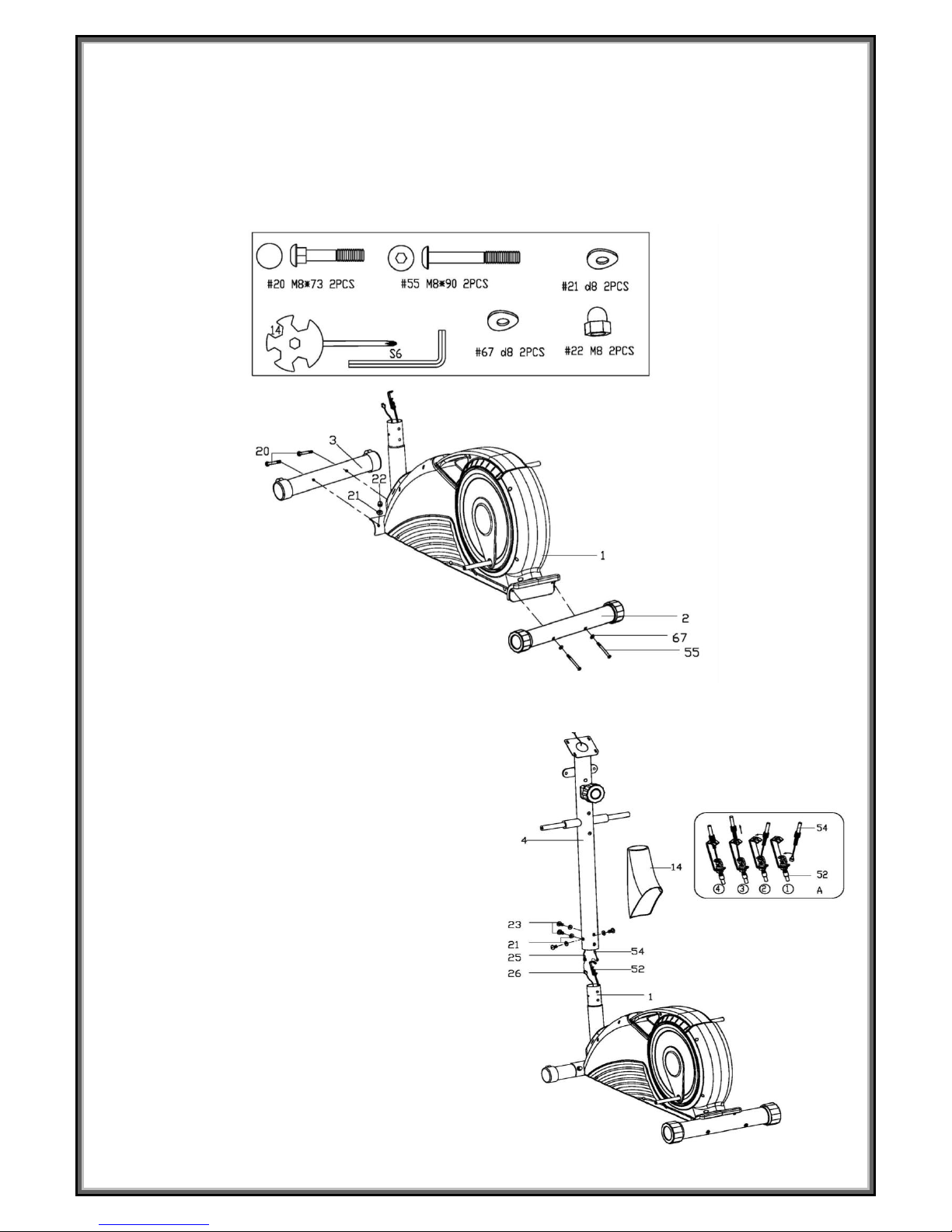
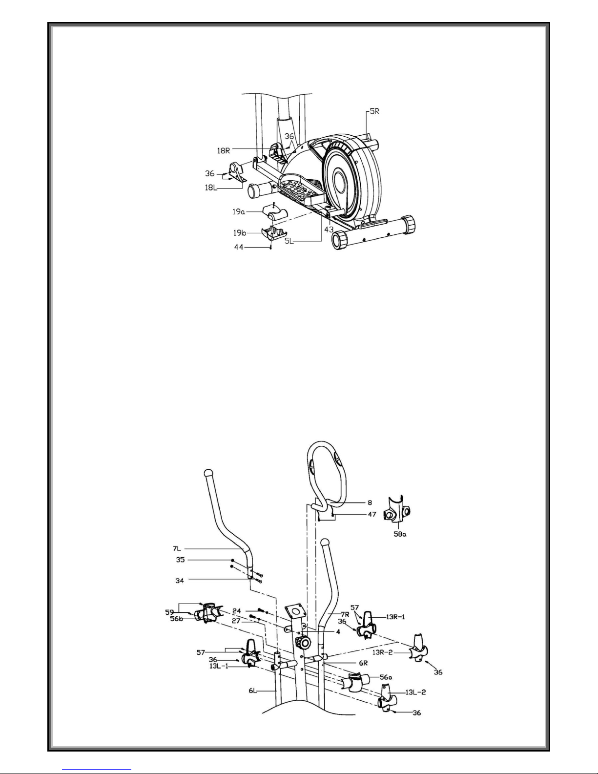
Follow the steps of the assembly instructions carefully.
Use only original parts as delivered.
Before the assembly, be sure to check if delivery is complete by using the included parts-list.
For assembly use only suitable tools and asks for assistance with assembly if necessary.
Place the exerciser on an even, non-slippery surface. Because of possible corrosion, the usage of any
exerciser in moist areas is not recommended.
Check before the first training and every 1-2 months that all connecting elements are tight fitting and
are in the correct condition.
Replace defective components immediately and/or keep the equipment out of use until repair. For
repairs, use only original spare parts.
In case of repair please ask your dealer for advice
Avoid the use of aggressive detergents when cleaning.
Ensure that training starts only after correct assembly and inspection.
For all adjustable parts be aware of the maximum positions to which they can be adjusted/tightened to.
This exerciser is designed for adults. Please ensure that children use the exerciser only under the
supervision of an adult.
Ensure that those present are aware of possible hazards, e. g. movable parts during training.
Warning: incorrect/excessive training can cause health injuries.
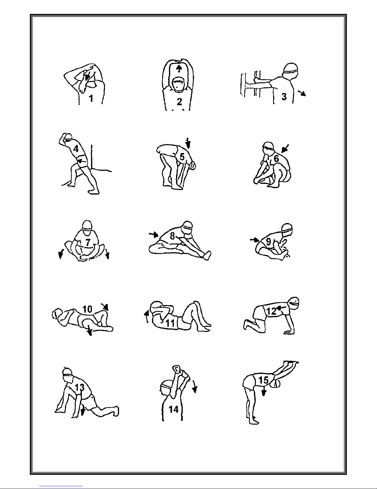
Please follow the advice for correct training as detailed in training instructions.
Consult your physician before starting with any exercise program. He can advise on the kind of
training and which impact is suitable.
The owner’s manual is only for customers’ reference.
The supplier can not guarantee for mistakes occurring due to translation or change in technical
specification of the product.
All data displayed are approximate guidance and cannot be used in any medical application

2
Warming Up:
15 seconds for each
20 seconds
20 seconds
25 seconds
20 seconds
20 seconds
30 seconds
25 seconds for each lag
30 seconds
20 seconds
5 seconds x 3 times
20 seconds
20 seconds for each leg
5 times
15 seconds

3
Assembly Instruction
Step 1:
1. Fix the Front stabilizer (3) to the Main frame (1) with Bolts (20), Arc washers (21), Nuts (22).
2. Fix the Rear stabilizer (2) to the main frame(1)with Bolts (55) and Arc washers(67).
Step 2:
1..Put the Protective guard (14) onto the
Handlebar post (4), connect the wire of
Tension controller (54) to the Tension wire (52)
as the picture A shown, and then fix the
Sensor wire (26) to the Connection wire (25).
2. Fix the Handlebar post (4) to the main frame
(1) with screws (23), Arc washers (21), and
then put the Protective guard (14) on.

4
Step 3:
1. Tighten the left and right Swing tube (6L/R) to the Handlebar post (4) with Bolt (28), spring washer (27)
and Flat washer (63).
2. Tighten the Pedal support (5L/R) to the Crank (60) with Bolt (65), spring washer (66), D-shape washer
(30) and Wave washer (33).
Step 4:
Fix the Pedals (17L/R) to the Pedal supports (5L/R) with Bolts (45), Flat washer (46) and Nylon nuts (61).

5
Step 5:
1. Fix the Protective guards (18L/R) to the Pedal supports (5L/R) with Screws (36).
2. Fix the Protective guards (19a/b) to the Pedal tube joints (43L/R) with Screws (44).
Step 6:
1. Fix the Handlebars (7L/R) to the Swing tubes (6L/R) respectively with Bolts (34) and Nylon nuts (35).
2. Firstly, set the Post cover (58a) on the Connecting piece of Handlebar post (4). Then fix the fixed
handlebar (8) to the Handlebar post (4) with Screw (24) and spring washer (27). Lastly, pass the Pulse
wire (47) through the hole in the back of the Handlebar post (4) and pull out of the hole of the Console
bracket.
3. Fix the left Protective guards (13L-1, 13L-2) to the junction of Swing tube (6L) and Handler bar (7L)
with Screw (36 ) and Screw(57), and then fix the right Protective guards (13R-1, 13R-2) to the junction
of Swing tube (6R) and Handler bar (7R) with Screw (36 ) and Screw(57).
4. Fix the Protective guards (56a/b) to the junction of Handlebar post (4) with Screws (59).

6
Step 7:
1. Connect the Connection wire (25) and Pulse wire (47) to the Console (10), and then fix the Console (10)
to the console bracket of the Handlebar post (4) with Screws (49) and Flat washers (48).
2. Fix the Post cover (58b) to the Post cover (58a) with Screw (36) and Screw (57).

7
Console Instructions
JVT-29108B
FUNCTIONS & OPERATIONS:
1.AUTO SCAN
After the monitor is power on or press Mode key, the LCD will display all functions values from
Time- Speed - Distance -Calories-Odometer- Pulse. Each value will be held for 6 seconds.
2.TIME
Accumulates total working time from 0:00 up to 99:59.The user may preset target time; each
press increase is 1 minute.
3.SPEED
Display the current training speed from 0.0 to 999.9 KPH or MPH.
4.DISTANCE
Accumulates total distance from 0.0 up to 999.9 km or ml. The user may preset target values.
5.CARLORIE
Accumulates calories consume during exercise from 0 to max, 999.9 cal. The user may
preset target values.
6.ODO/TOTAL DIST
Press the button until display ODO, total distance from 0 up to 9999 km or ml. Monitor will
display the total accumulated distance.
7.PULSE
Press the button until display ♥, monitor will display your current heart rate in beats percent
minute, 40~240 beats / minute.

8
KEY FUNCTION:
1.MODE
Press “MODE” to enter next function
[SCAN→TIMER→SPEED→CAL→PULSE→DIST→ODO].
2.UP
During the setting mode, press the key to increase the value of Time, Distance, Calories, and
Pulse.
Press the button and hold to speed up the increment.
3.DOWN
During the setting mode, press the key to decrease the value of Time, Distance, Calories, and
Pulse.
Press the button and hold to speed up the decrease.
4. ENTER(SET)
a. Press the button enter setting mode.
b. Press the key to accept the current data entry.
5. RESET
a. Press the button to reset function value when setting.
b. Press the button and hold for 2 seconds to reset all value except Odometer to be zero.
6. PAUSE
If you press the button, all function will stop, and LCD will flash, when you press the button
again, all function will be back to normal status.
Note:
If the computer displays abnormally, please re-install the battery and try again.

9
Exploded view (1)

10
Exploded view (2)

11
Part List
No.
Description
Qty
No.
Description
Qty
1
Main frame
1
53
Flat washer d12×Φ24×1.5
2
2
Rear stabilizer
1
54
Tension controller
1
3
Front stabilizer
1
55
Bolt M8×90
2
4
Handlebar post
1
56a/b
Protective guard
1pr
5L/R
Pedal support
1pr
57
Screw ST4.2X13
13
6L/R
Swing tube
1pr
58a/b
Post cover
1pr
7L/R
Handlebar
1pr
59
Screw ST4.2X18
17
8
Fixed handlebar
1
60
Crank
2
9
Foam grip
1
61
Nylon nut M8
6
10
Console
1
62
Nylon nut M10
3
11
End cap
2
63
Flat washer Φ8.2×Φ32×2
2
12
Foam grip
2
64
Sleeve Φ32×59
2
13L/R
Protective guard
2prs
65
Bolt M10X20
2
14
Protective guard
1
66
Spring washer d10
2
15
End cap
2
67
Arc washer d8×2×Φ25×R39
2
16
End cap
2
68
Screw ST3.5 X10
2
17L/R
Pedal
1pr
69
Tension spring
1
18L/R
Protective guard
2prs
70
Magnetic board axle
1
19a/b
Protective guard
2prs
71
Bolt M6X15
2
20
Bolt M8×73
2
72
Spring washer D6
6
21
Arc washer
d8×Φ19×1.5×R30
6
73
Flat washer D6×Φ12×1.5
2
22
Nut M8
2
74
Spring washer D20
2
23
Screw M8×16
4
75
Bearing
2
24
Bolt M8×30
2
76
Screw M6X15
4
25
Connection wire
1
77
Belt wheel
1
26
Sensor wire
1
78
Belt
1
27
Spring washer d8
4
79
Middle axle
1
28
Bolt M8X15
2
80
Nylon nut M6
4
29
Alloy sets Ф14×12.5×Ф10.1
4
81
Idler wheel
1
30
D-shape washer
28×Φ16.2×14×B5
2
82
Bolt M6 X55
1
31
Bushing 1
4
83
Nut M6
4
32
Axle
1
84
Spacer D10 ×Φ18×6
1
33
Wave washer
Φ17×Φ23×0.3
2
85
Screw M10×40
1
34
Bolt M8×40
4
86
Sensor
1
35
Nylon nut M8
4
87
Screw ST3X10
2
36
Screw ST4.2X18
13
88
Nut M10×1
2
37
Bushing Φ12×Φ32×15
4
89
Adjustable bolt M 6×50
2
38
Bushing Φ24×16×Φ16.1
4
90
Washer
2
39
Bolt M10×80
2
91
Magnetic board
1
40
Flat washerD10×Φ20×2
5
92
Wheel axle
1
41
Nylon nutM10
2
93
Nut M10× 1
2
42
Bolt M10×55
2
94
Wheel
1
43L/R
Pedal tube joint
1pr
95
Spacer D10×3
2
44
Screw M5X10
4
96
Flange nut M10×1.25
2
45
Bolt M8×45
6
97
Round magnet
1
46
Flat washer d8
6
98
Nut cap
1
47
Pulse wire
2
99L/R
Chain cover
1pr
48
Flat washer
2
100
Round disk cover
2
49
screw
2
101
Round disk
2
50
Arc washer d5
1
102
Spring washer D12
2
51
Screw M5X40
1
103
Square magnet
6
52
Tension wire
1
Table of contents
Other LA Fitness Elliptical Trainer manuals
Popular Elliptical Trainer manuals by other brands

Nautilus
Nautilus NE 2000 Assembly manual

NordicTrack
NordicTrack Audiostrider Cx650 Elliptical user manual

NordicTrack
NordicTrack E 8.5 Elliptical Manual do utilizador

Progear Fitness
Progear Fitness Air Elliptical owner's manual

Sole Fitness
Sole Fitness ST600 owner's manual

Body Flex Sports
Body Flex Sports BODY CHAMP BCB 5860 owner's manual

Body Champ
Body Champ TRIO-TRAINER BRT5350 owner's manual

Vision Fitness
Vision Fitness X6200HRT/DA owner's guide

True
True XC400 owner's manual

BH FITNESS
BH FITNESS iNLS14 BH Instructions for assembly and use

AsVIVA
AsVIVA CaridoBull S13 manual

LifeCore Fitness
LifeCore Fitness LC-CD400 User's product manual