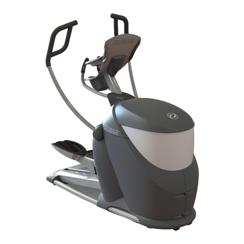
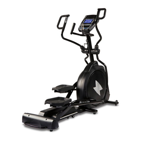
LA Fitness VORTEX User manual

ELLIPTICAL VORTEX
OWNER'S MAI{UAL

Screw
Bag
Allen Bolt Ir{8x|5{
I43)
-2PCS
TT .l
I_JJ
Bolt M8x60(146)-4PCS
SpringWasher
M8x2,0t black(67)-2
fi\
\y
Spring
Washer
M8x2.0tnickelplate
(139)-4PCS
Washer $ 22x'$
9xl.Ot{
144)-2PCS
Washer
$ lllx $9x2.0t(147)-4PCS
Scrcr,r'M4xl2
(55)
-4PCS
+f?
lln lln
"JJ "JJ
Bolr
M10x60
(141)-2PCS
Nylon
NutMl0 (142)-2PCS
AllenBolt
M8x42
(
148)-4PCS
Allen
Spanner
5MM(155)-1
PCS
Allcn Spanncr
6MM( I5
1)-1PCS
Screwdriver
(
1
49)-
IPCS

l.Assembly
ComPonents
Stabilizer(ll3i
I
I
A
ffi
ll"ll
n-N
g
TVCrompute{l22) -r I
L,=:"-'*
@ !
U- ffi comPurer{rre)
f- |
s tfl w ,l**,n",0,,j,
@B l) |
Transtbrme(
128)
Right
I'edal
{57) v$
EDdCap(|,lI)
Computer
Shelf(100)
PEdal
Cover{B)t124)
i-eftPedal
AssemblY(56)
atr
6aOO Gdt
6060 @o
E=:l E-i Ta Tn
-t ":B EII
r
I
le
t#
-tYFt-_
UprieJrt(
60)+Rocker(64)

2.To assemble
the Stabilizeffi Finish
2.1To
assemble
the
FrontStabilizer
Step
A-B:Attach
theFronr
Stabilizer(106)
to
the
Frame(1)
withBolts(146),
Spring
Washers(139)'
washers(147)and
tighten
theBolts(146)
with
Allen
wrench(155)
.
2.2Toassemble
theRearStabilizer
Step
A-B:Atrachthe
RearStabilizer(1
t3)
tothe
Frame(1)
withBolts(146),
Spring
Washers(139)'
washers(1
47)and
tighten
rhe
Bolts(146)
withAilen
wrench(155)
.
Assembly
Part
(146)
BoltM8x60 -4pCS (139)Spring
WasherM8x2.Ot (147)Washer 6 18x
S9x2'0t-4
NrckelDlate
-4PCS
146,139,147)
(is5)
\ .:"
(t46,139,147)
3
o-4
@o"
(147
,139,146)
(r13) (146,t39,147

3.
ToAssemble
theUpright
& Rocker After
Assemblv
Step
A: Remove
theBolts(i38),Spring
Washers(l39)
andArc Washers(14O)
with theLug
Wrench(150).
Step
B: Slide
theUpper
Front
Decorative
Cover
(47)onto
theUpnght(60)and
connect
the
Middle
Control
Wire(62)
totheLowerControl
Wire(i9).
Step
C:AttachtheUpright(60) to the
MainFrame(1)
ri,'ith
Boits(138),
Spring
Washers(
139),Arc
Washers(140)
and
tighten
the
Bolts(138)
withLug
Wrench(150),
thencap
theUpper
Front
Decorative
Cover(Upp
er){47
).
Step
A
(138.139,140)
>(1
50)
Step
B (60)
(60)
(138,139,140I___>

4.To
Assembte
the
ComPuter
Shelf
Before
AssemblY w_
AfterAssembly
Step
A: Remove
the Bolts (135),Spring Washers
Wrench(151).
(136).
and
theArc Washers
(137)with theAllen
Step
B: Make the Middle control wire (62) throughout of the computer
ComputerShelf(100)totheUpright(60)withBolts(135),Spring
Q:-
Shelf{100).
Attachthe
Washers
(136),and
Arc
washers
(137)
and
tighten
the
Bolts
(135)with
Allenwrench
(151)'
Step
A
(135,136,137L_- 51)
5.
ToAssemble
the
ComPuter AfterAssembly
Step
A: Unscrew
thescrews
(120)
with the
Philips
Sffewdriver
(
la9) fromthecomputer
{122)'
Step
B: Connect
the
upper control Wire(121)
tothe
Middle control wire (62)'
s.:
ffi,
(135,1
36,137\_-_1, (151)

Before
AssemblY
(143)AllenBolt (67)SpringWasherM8x20t (144)Washer
$22x$9x2'0t
M8x15-2PCS Black
-2PCS -2PCS
ffiffi oo @@
ULJ
{l4l) Bolt
M10x60-2PCS
(142)
Nylon
NutM10 -2PCS
=--if'
H
ffi
f55)
Screw
M4xl2 4PCS
6.To
Assemble
the
Pedals AfterAssemblv
Step
A_B:
Attach
theRightpedar
(57)tothe
MainFrame
(l) with Bolts(143),
Spring
washers
(67)
and
washem
(144),then
tighten
the
Bolt
(143)withAllen
wrench
(151)'
Step
C:Insert
the
Tube
Cap
(131)
intothe
RightPedal
(57)'
Step
B (1) (14tr,67.t44)
t143,67,144)
__->
(l3i)
o 'r- (l5l)

(r4e)
StepC:
Anach
theComput
er
(tZ2)tothe
Computer
Shelf
(100)with Bolts
(120)and
tighten
the
Screw
(120)
withPhilips
Screwdriver
(1a9)'
Step
D: Insert
theBookShelf
(
134)
into
theComputer
(l 19)'
(120) (14e)
(11e)
(134)

Step
D-E:
Atrach
the
Right
Pedal(57)
rothe
RockerExtension(
83)
withBolts(141)
and
Nylon
Nuts(142)
,tighten
theBolts(141)
and
the
Nyion
Nuts(142)
withtwoLug wrenches(150)
at
the
sametime.
Attach
rhePedal
Tube
Protecting
Cover(A)(123)
and
Cover(B)(124)
tothe
Right
withScrews
(
55
) and
tighten
the
Screws(55)
withPhilips
Screwdriver(
1a9).
Step
F-G:
Pedal(57)
(1
s0)
Step
E
(83)
(141,142
(141,142)
(t23)
(r24)
@^
ffi
G6
\JJJ --''#, (r4e) (5sI (14e)
Note:
Repeat
theabove
steps
A-G to assemble
the
Lift Pedal
(56).

7.To
Assemble
theHandrails
Before
Assembly AfterAssembly
Step
A-B: Makesure
thatthe"L" Logos
ontheLift Handrail
(91)and
theRocker
(64)are
in the
same
position,then
secure
theLift Handrail
(gl) and
theRocker
(6a)
with Bolts(148)and
tighten
theBolts
(148)
withAllen
Wrench
(151).
Nore:
Repeat
theabove
steps
A-B to assemble
theRight
Handrail
(92).
Step
C:Inserl
the
Hand
Pulse
Sensor
Wire
(96)into
the
HandPulseSensor
Phone
jack(1
19)on
computer.
the
ToAssemble
theComPuter
Power
Step
A: Plug
one
end
of the
Transformer
(128)
iil
(148)
Allen Bolt M8x42-4PCS
ffi-n
(61) H (el)
"L" Logo
\\u(lsl)
(148)
Step
r48)
\(15
1)
"L" Logo
intotheMainFrame
Power
Jack.

I
Step
B: Plugtheotherendof theTiansformer
(12S)
into-yourhomePowerJack.
Caution:Beforeyou connect
to your homepower,carcfully eheck
against
theparameterof the
Transformer,suchasthe input voltage, the output voltage alld.so6n'
Assemblv
isfinished.
(128)

ComputerOperationInstructions
1. Schematicdrawing
LCD DisplayScreen
Touch
Keys
2. Power
Up
Note:Self
generating
elliptical
requires
pedaling
topower-up.
Whenturned
on,the
display
with
emita long
beep
asall
LCD
displays
lightup.
Note:
Whenthereis
nosignalordata
input
for
4 minutes,themachine
willenter
sleepmode.
Pedalingthe
machine
orkeyselection
will
wake-up
theelliptical.
Quick
Start
Quick
Start
maybeused
atpower-up
and
with
allworkoutmodes.
Quick
Startatpower
up
will
defaultthe
elliptical
tomanualworkout
mode.
Note:Quick
startwill
set
work
outparameters
such
astime,
distance,
calories
todefault
values.

Pause
workoutcan
be
paused
by
pressinn
m Aflashing
"P'will
beltsplgyed
in
upper
leftcorner
ofpanel
indicatingworkout
ispaused.
workout
will
resumewhen
ffi
is
pressed
again.
Pulserecovery
After you start
it press ffi enter
theheartbeat
pulserecover.
The first 10secondsof thetest,it will
examtheheartbeat
pulse.( theheartbeat
pulsedisplays: it will countbackwards
60seconds
'
60secondslater
it will display
the
result
A+ -A-' B+-
B- .C+' C- ,
4+ isthebestresult
,C- isthe
worst.
If it shows
noheartbeat
pulse: It will back
tothe
non-exercise
mode)
After
startthemachineusers
can
0..r, ffi toenter
theexercise
mode
and
pressffio, or"r,
i fo, *o-" seconds
totheinitialposition,
press ru forthesecond
tigretoenterthe
heartbeat
pulse
recoveryexam.
Workout
Selection
There
are
4 basic
workoutmodes:
Manual,Pre-prograrn,User,Target
HR
Afrerpoweronilserscanpres'
ffi ,r m to
interchange
inManual,
pre-program,
user,
TargetHR.
Pressffi tosefect
desiredmode.
At
power
upuserscan
press
ffi toenter
theexercise
mode.
press
ro for
pause
and
press
t for
somesecondsto
theinitial
position,0."r,
I ", f tointerchange
Manual,Pre-program,User,Target
HR.
Press
ro to
selectdesired
mode.
HeartRateMonitoring
&Control
Allellipticals
have
heart
rate
monitoring
capability
through
contactheart
rate
grips.
This

Toinputdesiredvaluesr workout rnode.May
advance
flashing
prompt
to nextparameter
or
mode
forselection.

4. Setting
WorkoutParameters
After
selecting
OeJired
workout
mode:
Ma4ual,
Program,
User&Target
HR'you maypre-set
several
workout
parameters
fordesired
results'
WORKOUT
PARAMETERS:
RPM
SPEED
TIME
DISTANCE
WATTS
CALORIES
PULSE
Note:Someparametersare notadjustable
inq91.$j-n
programs'
once a programhas
been
selected,
pressing
n ,
will
make
" Time" parameter
flash'
Using
tr I you
may
select
desired
time
value'
Press
E g,llt" value'
F|ashingpromptwillmovetothenextparameter'Continueuseofil
il I until
desired
values
are
set'
Press
ffi to
begin
workout.
On
The
Fly
Ghanges
Parameters:
Time,
Distance,
etc,
maybe
reset
after
programbegins
by
presstng
when
in
pausemode,"
Time"
will
flash
anO
t X .unbe
used
toadjust
time'
-' """ o" useo
tocrear
varue.
press ffi tomove
flashing
prompt
tonext
ffi to
resume
workout'
value.
Repeat
sequence
for
other
parameters'
Press
I
:
i
i:

MoreAbout Workout Pararneters
Field trts$ay
Rsrse $tdrl*
lnfsrmat*on Eeraing De*cription
nilE
0: 00-9e Yas Yes 1. 1$"ien
disslayis0:80,TIME
willcount
up.
?. UfBn TffulE
is01:SO-S9:00.
itwillcountdsryn
ts 0.
THSTAHCE
o.ss-
s"go Yes Yas 1. Wren disptsy
iES:00,
SISTANCE
willesunt
up.
?. l*ltlenDl$TAfilOEiEO"10-
ffi,SS.itwillcqunt dcnarnto0.
PULSE 3tts240
tsPM Yes Yes Wh*n HeartReteexoeedseet
fange,ueer
wiflbe alened,
,-Gef'gq7a-24o)
GALORIE$
0&"990
cAr Yes Yes 1. lfiJhen
display
isS:S0,
CALC*IESwill
munt up.
2. WhenCALORIESis 10-
gg0. itwillcoufi ds'vn
to0.
WATT
30-450
vAFilgs
gY iTffiEL
Yes Yes t. \Atundisp{eyisO:nO,
rf,fATTS
willcountup.
RFM &25CI No Hg During
workoul"the
llfATT / CALORfE$t RFi'l
$FEf;P
fleld*$crotl ondisphy every$
.wonds,

5. Manual
Workout n'Ma{*ual"
Default
program
whenelliptical
is
quick
started
atpower-up.
il lH adjusts
work
resistance
levels.
Setting
Parameters
for Manual
Serect
"Mat?
uaf'bypressing
E o, ff pressm twice.
lstparameter
"Time"
will
flash
sovalue
canbeadjusted
usingn n
press l*to savevalue& move
to nextparameterto beadjusted.
Continue
through
all
desired
parameters,press ffi to
begin
workout.
.:,
;:"'
i.
:..
rq
Notes:1.
Parameterscanbereset
atany
time
during
workout,onthefly.
2.Some
parameters
arenot
adjustable
incertain
workoutmodes.
See
"Setting
Workout
Parameters"
forfurther
details.
::.
i:i

.:r. ---
"Manual'n
Operating
fnstruetbns
After tsrnonthemachio"
or"r, I n, f
I
"Manuat"oi"n"" n euick
start
withdefault
vatues'
I
I
tl
-I
I
Y
I
-
"
Time"flashes
I I.
I
i
I
"Distance"
flashesI I
r!
+
I
"Calories"
flashesI I
II
+
"Pulse"
flashesI f
I
t
-
-
-
lI BeginWorkout
!
t'tote:
I I ro,resistance
levels.

6. Pre-program
Workouts"
Program"
Thereare12
program
profiles
ready
foruse.
Allprogram profiles
have
16
levels
ofresistance
that
can
beuser
adjusted.
a rffiql
Profile #2
Profile#1
g@
Profile #3
g rTsffin
ffirs#n#F
J J
Profile #4
g rtrF]
H0w0
_H,8
# J
Profile #5 Profile
#6

Pre-
Programs
continued..'
gm
Profile#7
Profile#9
Profile
#8
a rmt
asgfis0
mB {} P
@aE@I@6
Profile
#10
Profile#11 Profile#12
Table of contents
Other LA Fitness Elliptical Trainer manuals