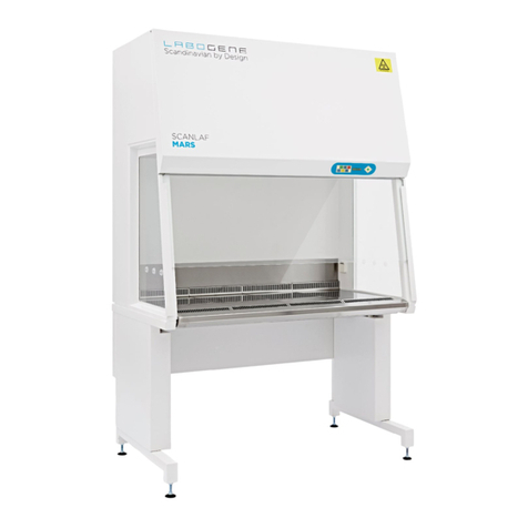
LaboGene Fortuna 900 User manual

12162017QA01
Item No. 700745
CopyRight © 2017
Page 1of 49
INSTRUCTION MANUAL
Fortuna
900, 1200, 1500 & 1800
Clean Bench

Instruction manual for Fortuna
12062017QA01
Item No. 700745
CopyRight © 2017
Page 2of 49
Symbols used in this manual
Note
Used to direct attention to a special item.
Warning
Used in case of danger of a serious accident or lethal injury.
Caution
Used in case of danger of medium or minor injuries or physical damage.
This document is the original instruction manual in accordance with the current Machinery Directive.
This document is the reference for any translation of this instruction manual. In case of doubts or
uncertainties the text in the original instruction manual is the valid.
LaboGene A/S
Bjarkesvej 5
DK-3450 Allerød
Phone No. +45 39 40 25 66
Fax No. +45 39 95 25 66
Internet www.labogene.com

Instruction manual for Fortuna
12062017QA01
Item No. 700745
CopyRight © 2017
Page 3of 49
Table of contents
1Introduction to this instruction manual.................................................5
2Introduction..............................................................................................5
2.1 Operating conditions and factory settings .................................................5
2.2 Compliance and basic features .................................................................5
2.3 Standard Fortuna cabinet..........................................................................6
2.4 Safety precautions.....................................................................................6
3Description...............................................................................................6
3.1 Safety systems ..........................................................................................6
3.2 HEPA filter .................................................................................................7
3.3 Control Panel: Standard set up .................................................................8
3.3.1 Control panel .............................................................................................8
3.3.2 Display.......................................................................................................9
3.4 Window positions.......................................................................................9
3.5 Lighting in working chamber....................................................................10
3.6 UV light ....................................................................................................10
3.7 Working area ...........................................................................................10
4Installation of the Fortuna cabintes.....................................................10
4.1 General considerations............................................................................10
4.2 Specific considerations............................................................................11
4.3 Transport..................................................................................................11
4.4 Sterile cabinets and open flames ............................................................12
4.5 Moving the Fortuna cabinets ...................................................................12
4.6 Connecting utilities to the Fortuna cabinets.............................................12
5Start-up of the Fortuna cabinets..........................................................13
5.1 Preparation ..............................................................................................13
5.2 Connections.............................................................................................13
5.3 Assemble the stand for the Fortuna cabinets..........................................14
5.4 Levelling of the Fortuna cabinets.............................................................14
5.5 Power connection of the Fortuna cabinets..............................................14
5.6 Installation test on the Fortuna cabinets..................................................15
6Operating the Fortuna cabinets ...........................................................16
6.1 Overview of the user menu......................................................................18
6.2 Programming ...........................................................................................19
6.3 Supervision –Alarm.................................................................................19
6.4 PIR sensor...............................................................................................19
6.5 Setting of light..........................................................................................20
6.6 Start-up of the Mars and Mars Pro cabinets............................................20
6.7 Operating modes of the Fortuna cabinets ...............................................20
6.7.1 Off mode..................................................................................................20
6.7.2 Working mode (Operating mode) ............................................................21
6.7.3 Standby mode..........................................................................................21
6.7.4 UV mode..................................................................................................21
6.8 Loading the working chamber..................................................................21
6.9 Working safely - Recommendations........................................................22
6.9.1 Before start-up.........................................................................................22
6.10 While working ..........................................................................................22
6.10.1 After work.................................................................................................23
6.11 Interrupting an ongoing procedure ..........................................................23
6.12 Shut down of the Fortuna cabinets..........................................................23
6.13 Disposal of cabinets.................................................................................24
Instruction manual for Fortuna
12062017QA01
Item No. 700745
CopyRight © 2017
Page 4of 49
Table of contents
7Cleaning/Decontamination of cabinets ...............................................24
7.1 Caring for and cleaning of stainless steel................................................24
7.2 Caring for and cleaning of coated surfaces.............................................25
7.3 Disinfection of working chamber..............................................................25
7.4 Rinsing of working chamber ....................................................................25
7.5 UV Disinfection after cleaning the working chamber...............................25
7.6 Microbiological decontamination .............................................................25
7.7 Cleaning of external surfaces..................................................................26
7.8 Cleaning the windows..............................................................................26
8Service and maintenance of Fortuna cabinets...................................26
8.1 Service on Fortuna cabinets....................................................................27
8.2 Working chamber lights, replacement .....................................................27
8.3 Optional UV lights....................................................................................28
8.4 Replacement of fuses..............................................................................28
8.5 Replacement of laminator........................................................................29
8.6 Replacements and repairs.......................................................................29
8.7 Disposal of cabinet ..................................................................................29
9Specifications ........................................................................................30
9.1 Spare parts ..............................................................................................34
10 Quality testing of the Fortuna cabinets...............................................35
10.1 Test terms and definitions........................................................................35
10.2 What is required by EN 12469 to be tested.............................................35
10.3 The factory quality test of the Fortuna cabinets.......................................35
10.4 The factory check list and factory test report...........................................35
10.5 Test equipment needed to perform installation tests and service tests ..35
10.6 Test information.......................................................................................36
11 Options for Fortuna cabinets ...............................................................36
11.1 LED light ..................................................................................................36
11.2 PIR sensor...............................................................................................37
11.3 Utility valves.............................................................................................37
12 Annex 1 - Factory check list and factory test report..........................38
13 Annex 2 - Service log book...................................................................47
14 Annex 3 - Decontamination statement ................................................48
15 Annex 4 - Declaration of comformity –Fortuna .................................49

Instruction manual for Fortuna
12062017QA01
Item No. 700745
CopyRight © 2017
Page 5of 49
1 Introduction to this instruction manual
This instruction manual gives a detailed description of the standard Fortuna cabinets: Functional
description and principle, installation, start-up, operation, cleaning and decontamination,
maintenance, specifications, testing and service log book.
2 Introduction
The Fortuna is a series of vertical sterile laminar airflow cabinets which incorporate the latest
laminator technology and energy-saving designs with HEPA-filtration and a range of options that
gives optimal protection of your product, samples or equipment.
The Fortuna range of cabinets, the ideal choice for your laboratory, wherever a sterile working area
is required. PCR, cell culture, microbiology applications, microprocessor manufacturing, plant tissue
culture, micro-electronics assembly, optics servicing, are just some examples of installations of the
Fortuna range.
2.1 Operating conditions and factory settings
The EN 12469 standard requires that the downflow air velocity is in the interval 0,25 m/s –0,50 m/s.
The LaboGene default downflow setting is 0,32 m/s for 350 mm work opening with a maximum
variation of ± 20% on single measuring points, which is in accordance with annex G in EN 12469.
Warning
The Fortuna cabinet should only be used with the work opening that is it set up for.
Running a Fortuna cabinet with a higher opening than the setup stipulates is NOT
recommended.
2.2 Compliance and basic features
The cabinets comply with the requirements stipulated in EN 12469.
The Fortuna cabinets have:
Microprocessor controller with:
LCD display indicating fan and alarm status.
Flow (Air velocity) sensors.
Clock (7 days) and hour-counter.
Pre-setting of automatic start-up, timer for delay start and timer for UV-light.
Alarm for any deviation from safety conditions.
Full programming of alarms and fans through pass word protection.
Ergonomically correct sloping front for maximum operator comfort.
Motor-driven sliding front window.
Side windows, for perfect light conditions and view to the surroundings.
Three air velocity modes: Fan off or reduced air velocity or normal air velocity.

Instruction manual for Fortuna
12062017QA01
Item No. 700745
CopyRight © 2017
Page 6of 49
One-piece table top for big working area.
Digital electrical direct adjustable Fan speeds.
2.3 Standard Fortuna cabinet
A standard Fortuna cabinet comprises:
The basic unit - four sizes 900, 1200, 1500 and 1800 including:
2 electrical outlets.
Side windows (left and right) with three holes.
For each cabinet, a support stand must be ordered.
2.4 Safety precautions
To avoid unintended or improper operation of the cabinet, please carefully read thismanual.
If you have questions related to the function or control of the cabinet or wish to order spare
parts, please always indicate the nameplate data.
Caution
The proper function and safety of the cabinet is only secured if personnel authorized
by us perform the required tests, maintenance and repair work.
Please also refer to sections “Testing” and “Maintenance”.
The following precautions must be taken for operation of the Fortuna-series.
Caution
Never operate the Fortuna cabinets if the fan compartment cover is removed.
If this cover is removed, the cabinet will give no protection of the operator or of the environment and
the fan will run with openly rotating blades.
Caution
Always keep hands and arms away from the work chamber when activating the
sliding window.
Caution
The airspeed monitoring system needs approximately 5 minutes to warm up and
stabilise after the fan has been switched on.
3 Description
3.1 Safety systems
The Fortuna cabinets have the following build-in safety systems:

Instruction manual for Fortuna
12062017QA01
Item No. 700745
CopyRight © 2017
Page 7of 49
Product protection
The steady airflow within the air system ensures constant
downflow, allowing the HEPA filter to remove contaminants so
that the product handled in the work chamber is always
surrounded by near particle free air.
The laminarity of the downflow air ensures that harmful
particles are not carried over the work chamber thus
preventing cross-contamination.
HEPA Filter
On the Fortuna cabinets, the downflow air within the work
chamber is cleaned by a HEPA H14 filter.
UV Safety
To protect from UV radiation, the optional UV light will not turn
on if the front window is open. While the UV light is on, the
front window must remain closed. The closed window blocks
out the UV rays.
Opening the window will cause the UV light to turn off. If the
light is turned on in the cabinet, the UV light will turn of
automatically.
Airflow monitoring
Monitoring of downflow air velocity guarantees that product
protection remains uncompromised.
Airflow monitoring, using build-in flow sensor, determine the
velocity of the airflow in the work chamber.
As soon as airflow velocity rise above or fall below a specified
alarm value, an audible and a visual alarm is activated.
3.2 HEPA filter
The filter system consists of a HEPA H14 filters for downflow
air.
Air is drawn from the surrounding room in through the prefilter
on top of the cabinet, through the HEPA H14 downflow filter and
laminator into work chamber.
The room air is mixed with recirculating HEPA filtered air from
the downflow in the work chamber, and filtered proportionally by
the downflowand exhaustfilters. Thefiltered air isthen supplied
as near particle free air into the work chamber of the cabinet,
and exhausted as near particle free air into the surrounding
environment, or into an external exhaust system.
Product name
Catalogue No.
Fortuna 900 downflow filter
9.000.050.001
Fortuna 1200 downflow filter
9.000.050.002
Fortuna 1500 downflow filter
9.000.050.003
Fortuna 1800 downflow filter
9.000.050.004
Downflow
filter
Prefilter

Instruction manual for Fortuna
12062017QA01
Item No. 700745
CopyRight © 2017
Page 8of 49
3.3 Control Panel: Standard set up
All functions are controlled by an electronic card with microprocessor via the control panel with
display shown below.
3.3.1 Control panel
1. Button 1with green LED light to select the fan ON/OFF at normal velocity. The green light
indicates that thefan is running at normal velocity, and that conditionsare safe. During start-
up the low flow alarm will be active and the LED only switched on when the conditions are
safe for working in the cabinet.
2. Button 2with blue LED to select the fan ON/OFF at reduced velocity. Can be adjusted to
any level desired for individual requirements (See Service menu). When switching to
reduced velocity the low flow alarm is activated and the light in the cabinet is turned off to
indicate not safe conditions.
3. Button 3with red LED. Alarm indicator with blinking red light and acoustic alarm. Press the
button to silence the acoustic alarm.
4. Button 4with blue LED for normal light ON/OFF.
5. Button 5with yellow LED to select ON/OFF of UV light (optional). The timer for the light is
set in the user menu (See User menu).
6. Button 6with blue LED can be connected to an internal plug in the chamber for remote
on/off of the plug/gas resettable valve.
7. Button 7: Window open (upwards movement).
8. Not active: Only for programming/navigation.
9. Not active: Only for programming/navigation.
10. Button 0: Window close (downwards movement).
11. Blue button “ENTER”.
Control
buttons
Display
Navigation
buttons
ENTER

Instruction manual for Fortuna
12062017QA01
Item No. 700745
CopyRight © 2017
Page 9of 49
3.3.2 Display
The display is used for showing the current running conditions or the current alarm condition. The
display is further used during setup of the cabinet in either user mode or service mode (password
protected).
Some examples:
In the top right-hand corner of the display, the navigation possibilities are shown. These are typically
left arrow (button 8), ENTER and right arrow (button 9).
On start-up after power disconnect or after power
failure the above alarm will be active. Press the blue
ENTER button to clear the alarm.
The main screen showing the time and date.
The display shows the current air velocity on flow 1,
which is the downflow air velocity by default. Value
in m/s.
3.4 Window positions
For easy loading and unloading of the cabinet, the window can be raised to create a 700 mm opening
on front of the cabinet.
On the Fortuna cabinets the work opening is 350 mm (default) or optionally 550 mm.
Window fully open,
opening 700 mm
Default work opening,
opening 350 mm
Window fully closed,
opening 0 mm
Optional work opening,
opening 550 mm

Instruction manual for Fortuna
12062017QA01
Item No. 700745
CopyRight © 2017
Page 10 of 49
3.5 Lighting in working chamber
All Fortuna has built in light in the working chamber. All cabinets are fitted with two florescent light
tubes mounted at the top of the working chamber to avoid disturbances of the airflow. This position
above the laminator gives a good and uniform light on the entire working area. The control system
allows the user to adjust the intensity from 0 to more than 750 Lux. The reachable light level is about
2000 Lux in the standardcabinets, measured onthe tabletops. LEDlight can optionallybe delivered.
Please refer to Options paragraph.
Product name
Catalogue No.
Light tube 900
9.000.040.011
Light tube 1200
9.000.040.012
Light tube 1500
9.000.040.013
Light tube 1800
9.000.040.014
3.6 UV light
The optional, factory-installed UV light is at the top of the front section of the working chamber. The
standard LaboGene control system is prepared for full control of safety and timing for the use of UV
light –see section “UV light option” for operation and build in safety measures.
Remember that UV light does not penetrate areas blocked from the direct light and that it does not
represent a substitute for good old fashion mechanical cleaning of the inner surfaces of the safety
cabinet.
3.7 Working area
All Fortuna cabinets are, as default, delivered with one solid fixed table top. They are designed for
easy cleaning, minimum vibrations and maximum working area. As standard it is made of 2 mm
stainless steel plate (AISI 304) wrapped around a chipboard for rigidity.
4 Installation of the Fortuna cabintes
4.1 General considerations
A sterile cabinet is a ventilated cabinet, which provides product protection. It has an open front and
back with outward airflow and downward HEPA filtered laminar airflow over the entire working area
for product protection.
The cabinets are neutral with respect to pressure in the room, as all air drawn into the cabinet is
exhausted back into the room.
Table top

Instruction manual for Fortuna
12062017QA01
Item No. 700745
CopyRight © 2017
Page 11 of 49
4.2 Specific considerations
To ensure that thebuild in safetyfeatures of the cabinets function properly, the location of installation
must be selected carefully. The recommended ambient conditions, for safe and proper operation,
are listed below.
All cabinets are developed and produced for use in clean environments.
Cabinets must not be operated outdoors or in environments with extreme air pollution. The
safety cabinets are not intended to filter vapours containing acids or organic solvents. The
safety cabinets must not be used as a fume hood.
Up to 2000 m above sea level.
The wall socket to which the cabinet is connected must be fused by a minimum 10 A fuse.
The wall socket should be placed so accidental switch off is unlikely. A wall socket without
a switch is recommended.
The power cord is the mains disconnect.
The location must be capable of supporting the weight of the device.
If the factory-approved stand is not purchased, the holding device must be rated for twice
the cabinet weight.
Adequate room height. For cabinets, which are not connected to an exhaust system, the
distance between the exhaust air opening on the cabinet and the room ceiling must be at
least 400 mm.
There must be at least 100 mm clearance on the rear and non-utility side of the cabinet.
For sides with external utility connections leave 150 mm clearance.
The location must be equipped with an appropriate ventilation system.
Room temperature between 10 °C and 35 °C.
Relative humidity must not exceed 80%, up to 31 °C and is decreasing linearly to 50% at
40 °C.
The cabinets are for indoor use only.
Room ventilation should preferably be a ventilation system that complies with the national
requirements for the application.
The inlet air and exhaust air openings of the room ventilation must be located so that drafts do not
impair the function of the sterile cabinet air system.
4.3 Transport
The cabinet can be moved through a standard 800 mm wide door.
Transport of the Fortuna cabinets can be carried out by lifting the cabinet using a forklift either
sideways under the support stand or directly under the trough. Furthermore, the cabinet can be
moved manually by using hooks in the dedicated holes in the support stand.

Instruction manual for Fortuna
12062017QA01
Item No. 700745
CopyRight © 2017
Page 12 of 49
Caution
Whenever transportation of the cabinet is needed, precautions should be taken to
prevent it from overturning due to the high-located mass centre.
Caution
To prevent damage to the cabinet it must be handled as fragile goods.
Storage of the cabinet must be in an environment of maximum 80 % relative humidity and at
temperatures between 5 °C to 50 °C.
4.4 Sterile cabinets and open flames
The provision of natural gas to sterile cabinets is not recommended. Open flames in the sterile
cabinet create turbulences, disrupt airflow patterns and can damage the laminator and the HEPA
filter. When suitable alternatives (e.g. disposable sterile loops, micro-incinerators) are not possible,
touch-plate micro-burners that have a pilot light to provides a flame may be used.
4.5 Moving the Fortuna cabinets
It is not recommended to move the Fortuna cabinets after installation. The moving of a cabinet can
result in safety issues, which can only be detected by re-testing of critical functions and properties.
If moving is warranted both the Fortuna can be lifted and moved using a low lifter (on 1500 and 1800
models use one from each side). Be aware that the cabinets are top heavy. Stabilize cabinet during
the moving process. On all Fortuna cabinets, the stand can be removed and moved separately.
Caution
Whenever transportation of the cabinet is needed, precautions should be taken to
prevent it from overturning due to the high-located mass centre.
Caution
In order to prevent damage to the cabinet it must be handled as fragile goods.
4.6 Connecting utilities to the Fortuna cabinets
If optional valves for utilities are delivered, make sure that local rules and regulations are complied
with during installation and use. It is generally recommended, to use an authorized technician for
this kind of work. Make sure that local rules and regulations regarding such installations are strictly
complied to.
Valves suited for any utility medium can be delivered. As default they are mounted in the holes in
the side windows. Optionally they can be mounted in the back wall.
Product name
Catalogue No.
Valve, gas
9.001.020.015
Valve, vacuum
9.001.020.016
Valve, carbon dioxide
9.001.020.017
Valve, nitrogen
9.001.020.018
Valve, compressed air
9.001.020.019
Valve, oxygen
9.001.020.020
Valve, water
9.001.020.701

Instruction manual for Fortuna
12062017QA01
Item No. 700745
CopyRight © 2017
Page 13 of 49
5 Start-up of the Fortuna cabinets
Caution
Correct assembly and installation is essential for proper start-up and operation of the
Fortuna cabinets.
5.1 Preparation
Caution
The installations site for the unit must be draught-free and should be selected so that
frequent passing of people in front of the work opening is avoided.
1. Adjust the levelling screws to assure that the table top is in horizontal position and levelled.
2. Valves for gases or vacuum are installed in the side windows. A qualified technician must
make the connections for the supply.
When the cabinet has been installed:
1. Check that the front window is in the correct position, i.e. parallel to the front shield.
2. Never lift the front window manually - this will cause window to mall function.
3. Check that the window slides from top to bottom without any irregular sound.
4. If the window does not move when the UP or DOWN button is pressed, authorized service
personnel must be called to correct the fault.
5. Always keep hands and arms away from the working chamber when activating the front
window.
5.2 Connections
Required fusing: Circuit breaker 10 A (13 A) or fuse T 10 A (T 13 A).
In addition, the applicable safety requirements of the local power Supply Company shall apply.
Caution
If an automatic relay for disconnection of power in case of electric fault is needed, it
must be installed in the supply, as it is not built-in.
Caution
Before connecting the power supply it must be checked that the mains specifications
correspond to those stated on the type plate.
Caution
The safety cabinet is provided with a flexible power cord. The connection may be
installed hard-wired or by means of a wall outlet with protective ground.

Instruction manual for Fortuna
12062017QA01
Item No. 700745
CopyRight © 2017
Page 14 of 49
If a hard-wired connection is used, a main switch, which will cut off all poles to the unit, must be
used. This switch must be lockable both in the ON and OFF positions.
5.3 Assemble the stand for the Fortuna cabinets
As default the Fortuna cabinets are delivered without the stand mounted.
Stand
Electrical stand
All nuts and bolts for assembly of the stand and for mounting the stand to the cabinet are delivered
with the stands.
Start by assembling the stand and then place the cabinet on top and fasten with four bolts –one in
each corner.
Product name
Catalogue No.
Stand, Fortuna 900, 75-80 cm
9.001.020.011
Stand, Fortuna 1200, 75-80 cm
9.001.020.012
Stand, Fortuna 1500, 75-80 cm
9.001.020.013
Stand, Fortuna 1800, 75-80 cm
9.001.020.014
Stand, Fortuna 900, 80-85 cm
9.001.040.011
Stand, Fortuna 1200, 80-85 cm
9.001.040.012
Stand, Fortuna 1500, 80-85 cm
9.001.040.013
Stand, Fortuna 1800, 75-80 cm
9.001.040.014
Stand, Fortuna 900, 90-95 cm
9.001.030.011
Stand, Fortuna 1200, 90-95cm
9.001.030.012
Stand, Fortuna 1500, 90-95cm
9.001.030.013
Stand, Fortuna 1800, 90-95 cm
9.001.030.014
Electrical stand, Fortuna 900, 75-105 cm
9.001.020.101
Electrical stand, Fortuna 1200, 75-105 cm
9.001.020.102
Electrical stand, Fortuna 1500, 75-105 cm
9.001.020.103
Electrical stand, Fortuna 1800, 75-105 cm
9.001.020.104
5.4 Levelling of the Fortuna cabinets
To ensure the best working conditions possible the cabinet must be levelled off before getting
released for normal operation.
Place a levelling device directly on the table tops and adjust the feet on the stand until the cabinet is
perfectly in horizontal level. Make sure that the cabinet is in horizontal level from side to side and
from front to back.
5.5 Power connection of the Fortuna cabinets
The Fortuna cabinets are connected to power through the delivered power cable. It is mounted in
the power inlet placed on top of the cabinet and to a standard power socket. All that is required is
230 VAC / 50 Hz connected to a 10 A or 13 A fused socket in the general electrical installation.

Instruction manual for Fortuna
12062017QA01
Item No. 700745
CopyRight © 2017
Page 15 of 49
Product name
Catalogue No.
Power cable, DK
Delivered with the
product.
Contact LaboGene if a
spare is needed.
Power cable, US
Power cable, GB
Power cable, EU
Power cable, AUS
5.6 Installation test on the Fortuna cabinets
The Fortuna cabinets must go through a series of test after installation has been finalized before
being released for normal operation.
As a minimum the following tests must be performed with satisfactory results:
Leak test of downflow HEPA filter
Downflow air velocity
Alarm settings (downflow alarms)
Smoke pattern test
The above mentioned tests are all associated with the safe operation of the cabinet. General
functionality is checked ad Hoc
To ensure optimal function and performance of the cabinet, the parameter values found in the
Factory test report must be used as close as possible. An installation test report covering all
necessary tests exists and can be acquired on demand from LaboGene.
Warning
The operational safety of the cabinet is guaranteed only, if all safety functions of the
cabinet have been tested and approved.
Caution
LaboGene will not warrant the operational safety if the cabinet is operated without
the required installation tests, or if these tests and are not performed by adequately
trained personnel.
Caution
The initial operation with subsequent installation test does not include any
decontamination measures. The working chamber and any accessories required
must be disinfected and cleaned in accordance with the hygiene guidelines set forth
for the desired application.

Instruction manual for Fortuna
12062017QA01
Item No. 700745
CopyRight © 2017
Page 16 of 49
6 Operating the Fortuna cabinets
All functions are controlled via the control panel shown below and by an electronic microprocessor
bases control system.
The control panel contains 6 buttons with LED for operating the basic functions in the cabinet, a text
display, that will show current running conditions and error messages and 5 buttons for navigational
purposes.
Button 1with green LED light to select the fan ON/OFF at normal velocity. The green light
indicates that the fan is running at normal velocity, and that conditions are safe.
Button 2with blue LED to select the fan ON/OFF at reduced velocity. Can be adjusted to
any level desired for individual requirements (See Service menu).
Button 3with red light to silence the acoustic alarm.
Button 4with blue light for normal light ON/OFF.
Button 5with yellow light is if UV light is required for decontamination or activation of the
table top. The time for the light is set in the user menu (See User menu).
Button 6can be connected to an internal plug in the chamber for remote on/off of the
plug/gas resettable valve.
Button 7: Window open (upwards movement).
Button 8: Only for programming/navigation.
Button 9: Only for programming/navigation.
Button 0: Window close (downwards movement).
Blue button: ENTER.
The user can by pressing enter see following User menu´s
Light intensity –in this menu the user can choose between 0-100 % light intensity to get
best light conditions. Please choose desired level and press enter.
Control
buttons
Display
Navigation
buttons
ENTER

Instruction manual for Fortuna
12062017QA01
Item No. 700745
CopyRight © 2017
Page 17 of 49
By pressing 8 or 9 the user can move to Display mode –where there is a possibility for
constant read out of velocity speeds –both inflow and down –flow –showed in m/s or in
counts from 0-255.
By pressing 8 or 9 again the user can see UV-light (if this is installed) and choose the time
for how long the UV –light should be activated.
By pressing 8 or 9 again the user can choose Auto start –auto stop. Here it is possible to
select Monday to Friday –whole week or only a single day when the cabinet should start
up in full speed and after how long it should wait until it switches off again.
By pressing 8 or 9 the Time setting on the cabinet can be set by the end user –date,
month, and year, clock 24 hours or AM/PM.
By pressing 8 or 9 Password shows up –this means the user can select a Password so
the keys cannot be activated –without the entered Password. It can always be overruled
by the Service access code.
By pressing 8 or 9 Service mode can be reached. To enter this you need to be trained
personnel and to have got the Service access code.

Instruction manual for Fortuna
12062017QA01
Item No. 700745
CopyRight © 2017
Page 18 of 49
6.1 Overview of the user menu

Instruction manual for Fortuna
12062017QA01
Item No. 700745
CopyRight © 2017
Page 19 of 49
6.2 Programming
Password protected access for trained personnel only!
Service mode: This menu is only operated by authorised service people from LaboGene,
distributors and trained technical people for safety reasons –who have got the Service access code.
In Service mode the following can be adjusted:
Airflow speeds downflow and exhaust through 2 air flow sensors.
The setting and calibration of the Alarms: Analogue air flow sensors or pressostats.
The configuration of the cabinet options: UV–light, light mode setting, electrical outlets, gas
resettable valves, PIR sensor.
External control setting: Output 0-10 VDC to volume gauge, external blower dampers or
CTS, inputfrom external blower or CTS or pressure gauge mountedin the exhaust channel.
Decontamination through H2O2or Formalin.
6.3 Supervision –Alarm
The cabinet safety is constantly supervised so that any deviation from safe conditions or any fault in
the supervision system will be indicated immediately.
Safe conditions are indicated by a green LED light in the button for fan at normal velocity. Unsafe
conditions will be indicated both acoustically and visually by red flashing LED light.
The alarm will be initiated if:
The vertical air velocity inside the work area is outside the limits.
The air volume exhausted is below the limits.
The fan is running at reduced velocity.
After a power failure AND on normal start-up.
Optional 3rd sensor: A sensor mounted in the exhaust channel.
By activating the alarm when the cabinet runs at reduced speed the red LED will change from
flashing to constant light.
The alarm will be deactivated when the fan is running at normal velocity, all conditions are safe, or
the cabinet is switched off.
(The whole display can be flashing if there is an alarm –this setting is done as a default in alarm
setting).
6.4 PIR sensor
If the operation of the cabinet has to be automatic –i.e. the cabinets is ready to work when the
operator stick the arms in the work chamber.

Instruction manual for Fortuna
12062017QA01
Item No. 700745
CopyRight © 2017
Page 20 of 49
In this case a PIR sensor can be mounted –let the cabinet run at full speed for defined time –as
long as there are movements. If no movements it will stop after the pre-set time from 60 seconds
and up.
In order to ensure the clean environment inside the cabinet, and that the cabinet instantly provides
operator safety –the cabinet has to run at reduced speed at all times during working hours
(programmable through the autostart –menu).
6.5 Setting of light
The light setting of the cabinet upon alarm can be set in 3 different alternatives:
Light always on when blue light button is activated.
Light always on when blue light button is activated and in full speed mode –if reduced
speed is pressed the light turns out.
Light is always on when blue light button is activated and in full speed mode –if there is an
alarm the light will turn off automatically and will only be turned on again when all alarms
have been deactivated.
6.6 Start-up of the Mars and Mars Pro cabinets
Turn on the cabinet by pressing the green button (1). The fans will start and the visible alarm in the
red button (3) will flash and audible alarm will be running until safe air velocityin downflow and inflow
has been reached. When the safe condition is reached the LED in the green button (1) will turn on.
The display will show the message below. Press the blue ENTER button to clear this message.
Turn on the light on in the cabinet by pressing the blue button (4). Move the window to working
position using the arrow UP (7) or DOWN (0) buttons.
The cabinet is ready for use with protection of product.
6.7 Operating modes of the Fortuna cabinets
The following are the operating modes for Fortuna cabinets:
OFF mode
Working mode
Standby mode
UV mode
6.7.1 Off mode
Off mode means the cabinet is in an idle state. The cabinet is turned off (light and fans are off). The
cabinet is connected to a power source.
This manual suits for next models
3
Table of contents
Other LaboGene Laboratory Equipment manuals

LaboGene
LaboGene CoolSafe 100-9 Touch Superior XS User manual

LaboGene
LaboGene ScanSpeed 1248 User manual

LaboGene
LaboGene SCANLAF Mars GS Series User manual

LaboGene
LaboGene Mars User manual

LaboGene
LaboGene CoolSafe Touch 700636 User manual

LaboGene
LaboGene CoolSafe User manual

LaboGene
LaboGene CoolSafe Basic 55-4 User manual
Popular Laboratory Equipment manuals by other brands

vita
vita VACUMAT 6000 M instructions

Agilent Technologies
Agilent Technologies BenchCel Microplate Handler quick guide

laerdal
laerdal LSU Directions for use

Showa Denko
Showa Denko Shodex PROTEIN LS-G 4J Operation manual

TA Instruments
TA Instruments RSA-G2 manual

SCHOTT
SCHOTT ColdVision Light Source Programming guide