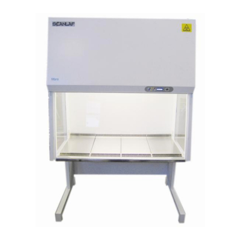
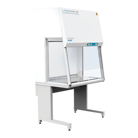
LaboGene Mars User manual

Edition 3 April 2012 Mars/Mars Pro Service Manual
Page 1/59
Mars/Mars Pro
Class 2- Biohazard Safety Cabinet
or Cytotoxic Cabinet
With automatic control system
MICROPROCESSOR BASED

Edition 3 April 2012 Mars/Mars Pro Service Manual
Page 2/59
Symbols used in this Manual
NOTE Used to direct attention to a special item.
WARNING
Used in case of danger of a serious accident / lethal injury.
Hazardous gases
RECYCLING!
Components and raw materials can be recycled.
Safety Gloves recommended!
Safety goggles recommended!
Electric shock hazard!
Biohazard!
Fire Hazard!
CAUTION!
Used in case of danger of medium or minor injuries or physical damage.
© Copyright, April 2012, Edition 3
Labogene APS, Industrivej 6-8, Vassingerød
DK-3540 Lynge.
Tel: +45 3940 2566; Mobil: +45 3016 0990;
Fax: +45 4498 1741
Internet: www.labogene.com
CVR-NR: 29009090

Edition 3 April 2012 Mars/Mars Pro Service Manual
Page 3/59
Page
1. General Notes 6
1.1 Safety instructions 6
1.2 Safety Standards 7
1.3 Warranty 8
2. Tools and Additional Items 9
2.1 Additional Items 9
2.2 List of tools required 10
3. Accessories 11
3.1 Exhaust system accessories 11
3.2 Support frames 14
3.3 Media valves etc. 15
3.3.1 Gas solenoid valve. 16
4. Light tube replacement 17
5. Internal Sockets 25
6. Window replacement 26
7. Controller operation 27
7.1 General operation and description 27
7.2 Main Menu 28
7.3 Sub menu options 29
7.3.1 LIGHT sub menu 30
7.3.2 SET WATCH menu. 30
7.3.3 DISPLAY MODEL menu 30
7.3.4 FAN AUTOSTART 30
7.3.5 SERVICE sub menu 30
7.3.5.1 MODEL sub menu 30

Edition 3 April 2012 Mars/Mars Pro Service Manual
Page 4/59
Page
7.3.5.2 RESET sub menu 30
7.3.5.3 FAN HOUR sub menu 31
7.3.5.4 FAN 1 Speed service menu 31
7.3.5.5 FAN 2 Speed service menu 32
7.3.5.6 FAN MODE Service menu 32
7.3.5.7 LIGHT MODE service menu 33
7.3.5.8 FLOW SENSOR service menu 33
7.3.5.9 ALARM setting service menu 34
7.3.5.10 U.V. MODE service menu 35
7.3.5.12 ALARM MODE Service menu 36
7.3.5.13 SERVICE KEY Service menu 37
7.3.5.14 EXT CONTROL Service menu 37
7.3.5.15 EXT ALARM DELAY Service menu 37
7.3.5.16 DECON Service menu 38
7.3.5.17 OPTIONS Service menu 39
7.3.5.18 LCD CONTRAST Service menu 39
7.3.5.19 LCD BACKLIGHT Service menu 39
7.3.5.20 LCD SLEEPMODE Service menu 40
8. Filter changing 41
9. Fan changing 45
10. Testing, commissioning and maintenance 46
10.1.Air velocity in Laminar flow 46
10.2 Air velocity for Inflow and exhaust 46
10.3 Air flow visualization 47
10.4 Filter testing 47

Edition 3 April 2012 Mars/Mars Pro Service Manual
Page 5/59
55
10.5 Front aperture retention test 48
10.6 Fuse replacement 49
11. Log Book 50
12. Decontamination statement 51
14. Wiring diagrams 44
15. Technical Specification 55
16. Wiring Diagram 56

Edition 3 April 2012 Mars/Mars Pro Service Manual
Page 6/59
1.1 Safety Instructions for service work and repairs.
Please note that any servicing or repairs to this product must be carried
out only by personnel with the appropriate qualifications and training.
They must have attended a LaboGene service training course on ScanLaf Cabinets
and have the appropriate certificate. Failure to show proof of this training will
invalidate the product warranty. Prior to carrying out any service on the product
or changing any components this service document must be read carefully and fully
understood.
Please also remember:
Any electrical work is to be carried out by trained electricians
Any work on gas lines / supplies is to be carried out by Corgi registered personnel (UK only) or by appropriately
trained engineers.
National and local regulations must be adhered to when any service work is carried out
The contents of this service manual are liable to change or be updated without notice.
For any service issues not covered adequately in this manual, please immediately contact Labogene at the Head
Office for your own safety.
WARNING !–Potential Contamination hazard!
The Safety Cabinet can be used for manipulations of Biohazardous and toxic materials so internal
components and filters can be contaminated. Service personnel must therefore observe strict safety precautions
when handling potentially contaminated material.
It is required by law that prior to service maintenance on any potentially contaminated zone that the cabinet is first
decontaminated by either formaldehyde vapour or hydrogen peroxide vapour (VHP) so any hazardous residues are
removed completely for the unit.
It is recommended that:
Prior to any maintenance work, the users should be asked about the potential hazards used and should make sure
that the cabinet is cleaned and decontaminated.
A certificate of decontamination from the operator is given to the service engineer.
WARNING ! –Electric shock hazard!
Contact with current carrying components and wiring may cause lethal electric shock. Motor driven components (eg Fans /
window motors) may cause injury if switched on accidentally. Prior to any repair work it is therefore recommended to
disconnect the cabinet from the mains supply source.
Isolate the cabinet from the electrical supply
Ensure the cabinet cannot be reconnected accidentally
Ensure any components such as capacitors etc are fully de-energized.
Ensure the cabinet is fully grounded.
Cover or isolate any nearby components that are still powered and under voltage.

Edition 3 April 2012 Mars/Mars Pro Service Manual
Page 7/59
CAUTION! –Hazardous Gases!
If the cabinet is connected to any external gas supply then this must be shut off prior to any service or
repairs.
Ensure the work area is adequately ventilated
Read any data sheets for gas supply / fittings
Report any faulty or suspect supply pipes to cabinet user / facility manager.
NOTE –Recycling
All cabinet components except the HEPA filters can be recycled.
If the cabinet has been used to process hazardous biological or chemical material (powders
etc) then it must be fully decontaminated prior to disposal and a Certificate of
Decontamination must be produced by the operator before removal from the laboratory.
NOTE –Start up after service / repair
If any safety devices (shielding / earthing etc) were removed or disabled prior to or during repairs then the
cabinet must not be started up until these devices are re-installed and checked for correct operation. Before
the cabinet is operated fully, it is recommended that a test run be carried out.
1.2 Standards and safety regulations.
The cabinet complies with, and has been tested to, the following standards and directives:
EN 12469:2000,
DIN 12980/2005/6
EN 292-1, EN 292-1,
EN 50081-1, EN 50082-1, EN 50081-2, EN 50082-2, EN 55011
IEC 801-2, IEC 801-4, IEC 1010-1 / EN 6101-1, UL 3101-1
EMC Directive 89/336 EEC-93/68/EEC
Low Voltage Directive 73/23 EEC-93/68/EEC
ENV 50140, ENV 50141
NFX 44-201

Edition 3 April 2012 Mars/Mars Pro Service Manual
Page 8/59
1.3 Warranty
Labogene guarantee the operational safety and functions of the cabinet provided that:
The cabinet is not modified or changed without authorization.
Only original spare parts or accessories as supplied by Labogene are used. Use of non original parts
will invalidate the warranty.
Maintenance and service checks are carried out at specified intervals.
A repeat commission test is carried out after any service or repair to components influencing these
tests.
The standard warranty period is 1 year from date of delivery.

Edition 3 April 2012 Mars/Mars Pro Service Manual
Page 9/59
2.1 Additional items
Screw connections
All screw connections are metric threads / sizes unless otherwise stated.
Screw securing
All retaining screws with diameters larger than 3mm should also be secured before they are tightened, with a separate
adhesive such as, recommended, Loctite 586 or similar.
Screw Torques
All retaining screws should only be tightened finger tight without additional leverage
Sealant
For areas requiring sealing with silicone we recommend Sista F 109 or similar.
Cleaner
For surface cleaning of components we recommend commercially available washing agents based on soap. Ensure all
parts are fully dry before reassembly.
Disinfectant
For standard disinfection of the work area we recommend spraying down with commercially available broad range
disinfectants. Wash down with distilled/deionised water then wipe down thoroughly with 70% ethanol or Isopropyl
alcohol. DO NOT USE COMPOUNDS CONTAINING HYPOCHLORITE SOLUTIONS OR CHLORINE
COMPOUNDS. These will adversely affect the stainless steel.

Edition 3 April 2012 Mars/Mars Pro Service Manual
Page 10/59
2.2 List of tools required
For routine service testing, we recommend instruments in accordance with the requirements of EN 12469:2000 for the
testing of airflows / filters and containment testing.
For repair servicing the following tools may be required:
Socket wrench set
6 –32mm
Slot-head screwdriver set
2 –6mm
Phillips screwdriver set
preferably magnetic
Open-ended wrench set
6 –32mm
Allen Key set
1.5 –6mm
Multimeter
U / I / Ohm
Diagonal cutter
small
Wire stripper
Flat connector pliers
Needle nose pliers
small
Tweezers
Starter punch
small
Spirit Level
small
Heat Gun
Soldering Iron
Solder
Cable ties
small , black
Shrink tube
6mm diameter
Shrink tube with sealant
6mm diameter
Flat connectors
6.3 mm
Wire end ferrules
1mm²

Edition 3 April 2012 Mars/Mars Pro Service Manual
Page 11/59
NOTE –Item numbers
The item numbers refer to the spare parts list at the end of this service manual. The catalogue number for the item will
be found in this spare parts list.
3.1 Cabinet Exhaust system accessories.
The safety cabinet can be equipped with a range of exhaust system accessories as shown Fig 1 Airflow sensor
1. Double exhaust filter –HEPA 9.001.020.109
Normally factory fitted but can be retro fitted if required.
Required in UK for recirculating Class II cabinets when working with Cat 3
biohazard material. Available for all cabinet models with 2 sizes available.
One for 900 and 1200 cabinets and one for 1500 and 1800 cabinets.
NOTE: When fitting or removing the secondary filter take care to avoid
damage to the air flow sensor
shown in Fig 1. Fig.1.
2. Double exhaust filter –Carbon 9.001.020.110
Normally factory fitted but can be retro fitted if required.
Required if working with organic / inorganic solvents that need to be removed
from exhaust air. Available for all cabinet models with 2 sizes available.
One for 900 and 1200 cabinets and one for 1500 and 1800 cabinets.
NOTE: When fitting or removing the secondary filter take care to avoid
damage to the air flow sensor
shown in Fig 2. Fig.2.
3. Direct duct kit for thimble extraction 9.001.020.122/123
This can be fitted to cabinets when the exhaust air is to be vented externally. It
allows the room air to be vented via the same duct extract. Available for all
cabinet models with 2 sizes available. One for 900 and 1200 cabinets and one
for 1500 and 1800 cabinets. Not suitable for use in UK. It consists of a 200mm
Ø duct spigot on a housing and will fit over the exhaust filter. Care must be
taken when fitting to avoid damaging the airflow sensor.
4. Direct duct kit with horizontal venting 9.001.020.118/120
This kit is designed for use when the cabinet is to be hard ducted with all air
vented externally. An anti blow back flap prevents the back flow of air to the
cabinet should a remote fan fail. This design is mandatory for all hard ducted
systems. The horizontal vent outlet is 200mm Ø and allows it to be mounted
with cabinets venting to the right or left by turning through 180º. Care must be
taken when fitting it to avoid damage to the airflow sensor. Available for all
cabinet models with 2 sizes available, one for 900 and 1200 cabinets and one
for 1500 and 1800 cabinets.

Edition 3 April 2012 Mars/Mars Pro Service Manual
Page 12/59
5. Direct duct kit with vertical venting 9.001.020.119/121
This kit is designed for use when the cabinet is to be hard ducted with all
air vented externally. An anti blow back flap prevents the back flow of
air to the cabinet should a remote fan fail. This design is mandatory for
all hard ducted systems. The vertical vent outlet is 200mm Ø and allows
it to be mounted with cabinets venting directly upwards. Care must be
taken when fitting it to avoid damage to the airflow sensor. Available for
all cabinet models with 2 sizes available, one for 900 and 1200 cabinets
and one for 1500 and 1800 cabinets.
6. VHP fumigation top plate 9.001.020.116
This plate is designed for use when fumigating re-circulating cabinets
with Vaporised Hydrogen Peroxide (VHP). It consists of a housing into
which is placed a 1” diameter Camlock used to connect to VHP
fumigation systems. It allows for the gases to be expelled from the
cabinet during fumigation.
(See relevant fumigation section) . It is suitable for both single and double
exhaust filter cabinets and is secured to the cabinet by means of spring clips as shown.
7.Formaldehyde / neutralization fumigation top plate.
9.000.020.115
When fumigating cabinets with formaldehyde it is necessary to
neutralize the gas after fumigation by means of ammonia. To prevent
the gases from escaping from the top exhaust filter on recirculating cabinets a top plate is
necessary, which covers over the filter and seals it off. It is secured by taping.
Plate included with formalin programming
8.Volt free contacts. 9.001.020.201
These are required if the cabinet is to be ducted to atmosphere and is required to give a signal to the remote
fan to start up / stop when the cabinet is operated.
They can also be used to give remote alarm outputs to building management systems etc. They are normally
factory fitted to the main control PCB board but can be retro fitted if necessary. Refer to wiring diagram
section for connections.
9.Pressure Switch. 9.001.020.202
These are required if the cabinet is to be ducted through a common exhaust system. It monitors the pressure
in the exhaust system and if the pressure drops sends a signal back to the control board which turns cabinet
off or into alarm condition

Edition 3 April 2012 Mars/Mars Pro Service Manual
Page 13/59
10. PIR sensor. 9.001.000.087
The PIR is used when fully automatic operation of the cabinet is required.
The cabinet is run at reduced speed and when the operator starts to work in the cabinet the
PIR sensor detects the movement and automatically sets the fans to run at normal speed. If no movement is
detected for 10 minutes then the fans automatically revert to reduced speed

Edition 3 April 2012 Mars/Mars Pro Service Manual
Page 14/59
3.2 Support frames
The Mars cabinet can be supplied with a choice of different support frames to give working heights as follows
9,001,020,011 Adjustable support stand to give work height of 75-80 cm for Mars 900
9,001,020,012 Adjustable support stand to give work height of 75-80 cm for Mars1200
9,001,020,013 Adjustable support stand to give work height of 75-80 cm for Mars1500
9,001,020,014 Adjustable support stand to give work height of 75-80 cm for Mars1800
9,001,030,011 Adjustable support stand to give work height of 90-95cm for Mars 900
9,001,030,012 Adjustable support stand to give work height of 90-95 cm for Mars1200
9,001,030,013 Adjustable support stand to give work height of 90-95 cm for Mars1500
9,001,030,014 Adjustable support stand to give work height of 90-95 cm for Mars1800
9,001,040,011 Adjustable support stand to give work height of 80-85 cm for Mars 900
9,001,040,012 Adjustable support stand to give work height of 80-85 cm for Mars1200
9,001,040,013 Adjustable support stand to give work height of 80-85 cm for Mars1500
9,001,040,014 Adjustable support stand to give work height of 80-85 cm for Mars1800
There is also an electrically adjustable support frame available as follows:
9,001,020,101 Electrical elevation stand 75-105 cm M900
9,001,020,102 Electrical elevation stand 75-105 cm M1200
9,001,020,103 Electrical elevation stand 75-105 cm M1500
9,001,020,104 Electrical elevation stand 75-105 cm M1800
When delivered the support frames are flat packed and need to be assembled. Each frame will consist of 3 components :-
the rear bracket / kick panel (C), and 2 side frames, (D).
To assemble the frame screw the rear panel (C) to the side frames in
positions (A) using the screws supplied with the frame ensuring that the
rear panel is mounted so as to be flush with the top of the frame and the
lipped side faces rearwards. The frame height can be adjusted up to
50mm by screwing in or out the feet (B). Ensure they are locked into
position with the locking nuts and that the frame is level before
lowering the cabinet onto the support frame.
Once the cabinet is in position then secure the cabinet to the frame by
screwing in the retaining screws into positions (E) which will ensure the
cabinet is correctly fixed to the frame. Access to these screws is from
under the top frame crossbar.

Edition 3 April 2012 Mars/Mars Pro Service Manual
Page 15/59
The electric frame is installed in the same way with the exception that the side panels house the electric motors for raising /
lowering the cabinet.
On the rear of the frame is positioned the motor connection box from which the power cable is taken. The power cable
must be connected to a suitable mains voltage power source.
3.3 Media valves (Gas / Vacuum )
The Mars cabinet is designed to accept the fitting of media connections through the
side windows. Both side windows are, as standard, provided with one hole of Ø
23mm for the fitting of such connections. If more media connections are required
then the window can be replaced with one having 3 holes (see Fig 2 item 9).
The media valves are colour coded in accordance with international standards so it is
important to install the correct valve for the purpose required. If flammable gas is required
in the cabinet then the gas line must also be fitted with an electric solenoid valve, which
will cut off the gas supply in the event of a power failure. (Part No 9,000,020,030). This
will be fitted to the inlet pipe on the outside of the cabinet and wired back to
the main control board as detailed in part 3.3.1.

Edition 3 April 2012 Mars/Mars Pro Service Manual
Page 16/59
3.3.1 Gas solenoid valve.
This is required when a mains supply of flammable gas is to be used in the cabinet and is mandatory under EN
12469:2000. It ensures the gas supply is shut off in the event of a power failure.
Parts required:
Part no, 9.000.020.015 gas valve, 9.000.020.030, Gas solenoid valve, 9.001.020.201, external PCB
To connect:
1Fit the gas valve to the cabinet as detailed in point 3.3 above and ensure the valve is correctly tightened.
2Fit the solenoid to the outside of the gas valve and secure tightly.
Run the solenoid cabling along the side of the window and up to the top of the cabinet and secure using
tie wraps and adhesive pads.
3 From the gas solenoid connect the neutral connection at the 230v input on the main board. Connect the earth
from the valve to the earth input at the same location. Connect the live connection on the valve to the NO
(normally on) connection on Relay 1 on the external PCB. Then make a connection from the live output on the
230v input to the COM (common) connection on Relay 1. Button 6 is then used to turn the gas supply on or off
4 Fit the external gas supply source to the inlet valve of the solenoid (NOTE: This should only be done
by personnel authorized and trained to work with flammable gas appliances)
3.3.2 PIR sensor installation
This can be installed when full automatic control of the cabinet is required
Parts required 9.001.000.087
To connect:
1 Fix PIR sensor in place directly under the laminator in the centre of the cabinet.
2: Fix wires underneath the laminator and take wire up to main control board.
3: Strip back cable and identify the three black wires, labelled 1, 2 and 3. Connect cables to orange block on main board to
connections 1,2 and 3 as shown in picture (middle block of 3, 3-1 left to right.
4:Press black enter button and o into service mode with code 8899, scroll to Flow senso settings and select sensor 3 the
AOS, once in AOS set the time in secs 600 (this is the time that the fans runs after it has detected no movement

Edition 3 April 2012 Mars/Mars Pro Service Manual
Page 17/59
Item No 10 Spare light tube
Two light tubes are installed in each Mars cabinet above the laminator sheet. To access the light tubes, the laminator sheet
must first be removed. (See fig 3 below)
To access the laminator sheet it is first necessary to raise the motorized window to the highest position allowing a fully
open work area.
1. Pull the 2 ribbons on the laminator towards the front of the
cabinet
to compress the sprung brackets (see (A) below in Fig 5) and
then
downwards to the base of the cabinet. This will allow the
laminator
and frame to drop down. Take care to avoid it dropping
completely
and causing damage.
2. Remove the laminator from the cabinet and place in a secure place
to avoid inadvertent damage. Fig. 3.
3. The fluorescent light tubes can then be seen along the top front and
rear of the cabinet work area. (See Fig 4)
4. Ensure the power is turned off and rotate the tube through 90º so
5. the tube is free of the connections and carefully remove it from the Fig 3 Removal of cabinet. Laminator
6. Repeat the procedure with the other tube if both are to be replaced.
7. Insert a new tube in the reverse procedure.
8. Replace the laminator by positioning it carefully towards the front of the cabinet and then raising into position at
the back, locating it securely above the flanges around the edge of the work zone.
Fig. 4. Showing light tube at rear. Fig. 5. Showing clips (A).
Cat. No.:
9.000.050.007 Light ballast for Mars/Fortuna 900 –1200
9.000.050.008 Light ballast for Mars/Fortuna 1500 –1800
9.000.040.011 Light tube for Mars/Fortuna 900
9.000.040.012 Light tube for Mars/Fortuna 1200
9.000.040.013 Light tube for Mars/Fortuna 1500
9.000.040.014 Light tube for Mars/Fortuna 1800

Edition 3 April 2012 Mars/Mars Pro Service Manual
Page 18/59
Item N o 11 Spare UV tube
The UV germicidal tube (when fitted) is located on a platform on the inside front wall of the cabinet above the work area.
It is fitted by means of a locking device and relevant ring nuts. The light is emitted at a wavelength of 254nm, which
produces deactivation of proteins and nucleic acid strands, thus sterilizing the work area. Since UV irradiation is harmful
to skin, the operator and the environment around the cabinet must be protected from accidental exposure, and therefore the
UV light is only functional when the window is fully closed. (To set up UV exposure times see relevant section under
“Controller settings”)
The average life time under normal operation is expected to be around 3000 working hours but since the UV
effectiveness reduces with time it is recommended that the UV tube be replaced annually if used regularly (daily) or at a
running time of no more than 2000 hours.
To replace the UV lamp proceed as described below:
1Raise the motorized front window to the full open position to allow access to the work area.
2Rotate the ring nuts anticlockwise until they unhook, release them from the tube as shown in Figure 7
3Rotate the germicidal tube 90º to release it from it’s seating.
4Release the ring nuts from the germicidal lamp and transfer them to the new lamp.
5Fit the new lamp by following the procedure in reverse order.
Under certain circumstances, it may be necessary to replace the Lamp starter as well. The starter can be found on the side
of the platform. To replace it, simply rotate it anti-clockwise until it loosens, release it, replace with a new starter and
rotate clockwise until secure.
Product No.:
9.000.050.010 UV light ballast
9.000.040.001 UV light tube for Mars / Mars Pro / Fortuna

Edition 3 April 2012 Mars/Mars Pro Service Manual
Page 19/59

Edition 3 April 2012 Mars/Mars Pro Service Manual
Page 20/59
This manual suits for next models
1
Table of contents
Other LaboGene Laboratory Equipment manuals

LaboGene
LaboGene ScanSpeed 1248 User manual

LaboGene
LaboGene Fortuna 900 User manual

LaboGene
LaboGene SCANLAF Mars GS Series User manual

LaboGene
LaboGene CoolSafe User manual

LaboGene
LaboGene CoolSafe Basic 55-4 User manual

LaboGene
LaboGene CoolSafe 100-9 Touch Superior XS User manual

LaboGene
LaboGene CoolSafe Touch 700636 User manual