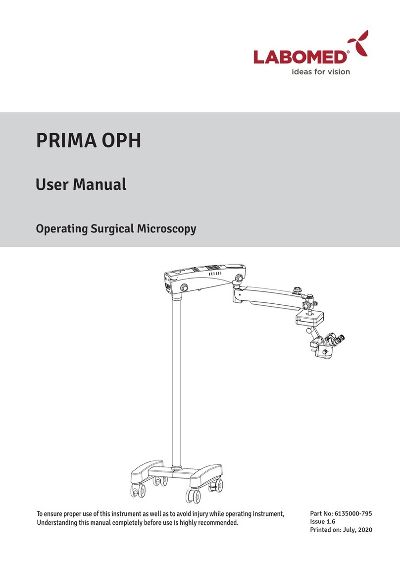
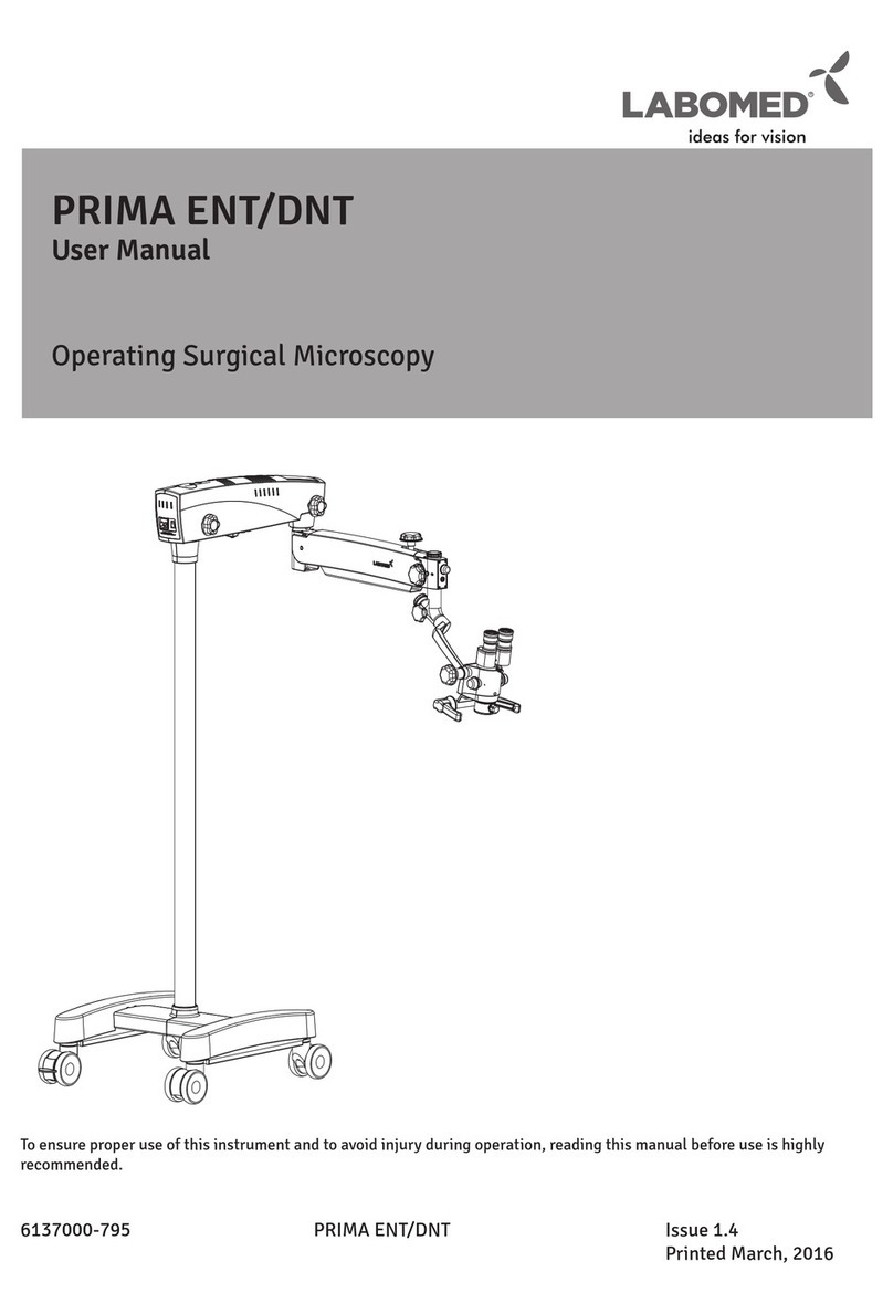
Labomed PRIMA DNT User manual

Prima
PRIMA
User Manual
Operating Surgical Microscopy
To ensure proper use of this instrument as well as to avoid injury while operating instrument, understanding this manual
Completely before use is highly recommended.
6137000-795 Issue 1.9
Printed on Sept,2021

6137000-795
Prima
PRIMA is a Trade name of LABOMED Microscopes.
LABOMED is a registered trademark of Labo America, Inc.
All other trademarks are the property of their respective owners.
The information contained in this document was accurate at the time of publication. Specifications are subject to
change without prior notice. LABOMED reserve the right to make changes to the product described in this user
manual without notice and without incorporating those changes in any products already sold.
ISO 9001/13485 Certified - LABOMED products are designed and manufactured under quality processes that
meet ISO 9001/13485 requirements.
No part of this publication may be reproduced, stored in a retrieval system, or transmitted in any form or by any
means: electronic, mechanical, recording, or otherwise, without the prior written permission of LABOMED.
Issue 1.9
Printed on Sept,2021
6137000-795 Prima Issue 1.9
Printed on Sept,2021

TABLE OF CONTENTS
1. INTRODUCTION AND INTENDED USE 1
2. PRODUCT DESCRIPTION 2-3
3.DIMENSIONS OF CEILING MOUNT 4-5
4. INSTALLATION REFERENCES (CEILING MOUNT) 6-11
5. CEILING MOUNT INSTALLATION 12-14
(A) DROP CEILING APPLICATIONS
(B) LEVELING THE CEILING MOUNT SYSTEM
(C) INSTALLING CEILING MOUNT ON CONCRETE CEILINGS
6.INSTALLATION REFERENCES (CONCRETE CEILING MOUNT) 15-16
7.DIMENSIONS OF WALL MOUNT ASSEMBLY 17-19
8.INSTALLATION OF WALL MOUNT 20
9.DIMENSIONS OF WALL MOUNT 21
10.INSTALLATION REFERENCES (WALL MOUNT) 22-24
11. WALL MOUNT INSTALLATION 25-27
12.WALL MOUNT INSTALLATION PROCEDURE 28-34
13. WARNING AND CAUTIONS 35-36
14. EXPLANATION OF SYMBOLS 37
15. STANDARDS AND DIRECTIVES 38
16. CONDITION OF INSTRUMENT AT TIME OF UNPACKING/SUPPLY 39
17A. INSTALLATION OF BASE (MOBILE STAND) 40-41
17B. MICROSCOPE INSTALLATION 42-43
18. ELECTRICAL CONNECTIONS 44-45
19. CONTROL ELEMENTS 46-47
20. INSTRUCTIONS FOR USING THE MICROSCOPE 48-49
21. CHANGING THE OBJECTIVES & EYEPIECES 50
22. USE OF ACCESSORIES 51-52
23. THERMAL CUT-OFF 53
24. TENSION ADJUSTMENT 53
25. MOVING POSITION OF THE SYSTEM 54
26. CARE AND MAINTENANCE 55-56
27. CLEANING AND DISINFECTION 57
28. AMBIENT REQUIREMENT 58
29. DISPOSAL 58
30. TROUBLESHOOTING TABLE 59-60
31. TECHNICAL SPECIFICATIONS 61
32. GUIDANCE TABLES 62-65
33. MEASURES AND WEIGHT 66
34. GLOSSARY 67
35. WARRANTY 68
Prima
6137000-795 Prima Issue 1.9
Printed on Sept,2021
1. INTRODUCTION AND INTENDED USE
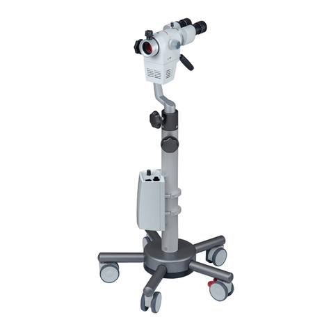
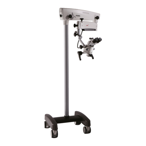
The LABOMED Prima is a surgical and diagnostic microscope which is adaptable for different surgical needs
for consistent sualization during all intra operative phases of ENT & dentistry surgeries
by proding magnified ew of the surgical field without compromise to performance.
The microscope prodes extremely high optical image quality, good depth of focus and wide field of ew for
precise surgery. Illumination control, inbuilt tilt, adjustment of the observation head help to reduce the
Surgeon's work fatigue and allow comfortable use over long period.
Salient features of this Microscope are:
1. The observation head can easily be positioned with the help of a suspension arm.
2. An advanced 5-step magnification changer allows an optimal magnification for a particular surgery
from five different magnifications.
3. Cold light illumination with a high intensity 50W LED lamp is proded in magnichanger for proper
illumination. The illumination is further adjustable up to its most suitable brightness using intensity
control knob suitably located at the suspension arm, and is easily approachable to the surgeon.
4. When the microscope is not in use, the suspension arm can be folded over the main body to store it
compactly.
5. Dual iris Diaphragm allows greater depth of field particularly valuable for photography.
6. Rigid H-form base with castor wheels prodes greater stability as well as mobility to the instrument.
INTENDED USE
Prima Surgical Microscope is an AC powered dece intended for use during diagnosis and Surgery
to prode a magnified ew of surgical field. .
Note:
The use of Prima Microscope is purely for intended use.
CONFIGURATIONS
Microscope Catalogue No.
Prima ENT
6137000-000
Prima DNT 6138000-000
Prima
6137000-795 Prima Issue 1.9
Printed on Sept,2021
1

2. PRODUCT DESCRIPTION
Fig. 1
1. Wheel with Brakes 15. Magnification changer
2. H shape metal Base 16. Handle
3. Column 17. Common Main Objective
4. Swivel arm 18. Magnichanger locking knob
5. Suspension arm 19. Illumination Control Knob
6. Swivel Arm Locking Knob 20. Fine focusing knob
7. Suspension arm movement locking knob 21. On/Off switch
8. Inclined Coupling locking knob 22. Power inlet
9. Inclined coupling
10. Carrier Locking knob
11. Suspension arm hydraulic movement lock
12. Suspension arm spring tension adjustment
13. Swivel arm cover
14. Binocular head with eyepieces
18
13 4
5
9
19
12
17
7
11
10
8
16
14
15
1
2
3
20
21
22
Catalog no. 6138000-000
Model : Prima DNT
Prima
6137000-795 Prima Issue 1.9
Printed on Sept,2021
2

Fig. 1.1
1. Wheel with Brakes 15. Magnification changer
2. H shape metal Base 16. T - Handle
3. Column 17. Common Main Objective
4. Swivel arm 18. Magnichanger locking knob
5. Suspension arm 19. Illumination Control Knob
6. Swivel Arm Locking Knob 20. Foot Paddle for Z- axis
7. Suspension arm locking knob 21. Fine focusing knob
8. Inclined Coupling locking knob 22. On/Off switch
9. Inclined coupling 23. Power inlet
10. Carrier Locking knob
11. Suspension arm hydraulic movement lock
12. Suspension arm spring tension adjustment
13. Swivel arm cover
14. Binocular head with eyepieces
20
LABOMED
LABO AMERICA,
I9N2C0,. Auburn Court
Fremont CA 94538
USA
www.laboamerica.com
Y
Part # ..................
R
IP X6
1
2
3
13 4
7
511
9
19
8
10
14
15
16
17
18
12
21
22
23 6
Catalog no. 6137000-000
Model : Prima ENT
PRODUCT DESCRIPTION(continued)
Prima
6137000-795 Prima Issue 1.9
Printed on Sept,2021
3

Fig. 2
3.DIMENSIONS OF CEILING MOUNT
CEILING MOUNT WITH STANDARD SUSPENSION ARM
PRIMA CEILING MOUNT DESIGN
FORMULA TO CALCULATE MICROSCOPE COLUMN LENGTH
COLUMN LENGTH = (FLOOR TO CEILING HEIGHT - 1755mm)
GIVEN EXAMPLE :- COLUMN LENGTH = 3660mm - 1755mm = 1905mm
525mm 600mm91mm
±250mm
±180° ±150°
CONCRETE ROOF
3660mm (12')
1426mm
260mm
1730mm
1106mm
1571mm
1401mm
Fig. 2
Prima
6137000-795 Prima Issue 1.9
Printed on Sept,2021
4

CEILING MOUNT WITH LONG SUSPENSION ARM
525mm 922mm91mm
±250mm
±180° ±150°
CONCRETE ROOF
3660mm (12')
1426mm
260mm
1730mm
1106mm
1571mm
1401mm
DIMENSIONS OF CEILING MOUNT(continued)
Fig. 3
Prima
6137000-795 Prima Issue 1.9
Printed on Sept,2021
5

CEILING MOUNT: ALTERNATIVE INSTALLATION TO THE PATIENT’S
SIDE WITH STANDARD ARM
4. INSTALLATION REFERENCES (CEILING MOUNT)
Fig. 4
Prima
6137000-795 Prima Issue 1.9
Printed on Sept,2021
6

CEILING MOUNT: ALTERNATIVE INSTALLATION TO THE PATIENT’S
SIDE WITH LONG ARM
986mm
799mm
INSTALLATION REFERENCES (CEILING MOUNT)(continued)
Fig. 5
Prima
6137000-795 Prima Issue 1.9
Printed on Sept,2021
7

WORK RANGE RECOMMENDED FOR IDEAL INSTALLATION SITE
STANDARD ARM
INSTALLATION REFERENCES (CEILING MOUNT)(continued)
Fig. 6
Prima
6137000-795 Prima Issue 1.9
Printed on Sept,2021
8

WORK RANGE RECOMMENDED FOR IDEAL INSTALLATION SITE
LONG ARM
986mm
R1270mm
R1633mm
933mm
INSTALLATION REFERENCES (CEILING MOUNT)(continued)
Fig. 7
Prima
6137000-795 Prima Issue 1.9
Printed on Sept,2021
9

MARKING REFERENCE
A
B
C
DE
175mm175mm
175mm175mm
400mm
400mm
INSTALLATION REFERENCES (CEILING MOUNT)(continued)
Fig. 8
Prima
6137000-795 Prima Issue 1.9
Printed on Sept,2021
10

2016
96
308
155
69
60
1935
38
400
INSTALLATION REFERENCES (CEILING MOUNT)(continued)
Fig. 9
Prima
6137000-795 Prima Issue 1.9
Printed on Sept,2021
11

5A. DROP CEILING APPLICATIONS
Many newer constructions use drop ceilings. Whenever this type of application is used, all supporting
structure and electrical serce (115/230 VAC, 15A ) is the customer's responsibility and must be completed
before the installation.
WARNING: THE SUPPORTING STRUCTURE FOR THE CEILING MOUNT AND WALL MOUNT INSTALLATION
MUST BE CAPABLE OF SUPPORTING A MINIMUM WEIGHT OF 600 LBS (272 kg) AND BE STABLE
LATERALLY AND VERTICALLY, AND FREE FROM VIBRATION.
WARNING:
• CEILING MOUNT PLATE AND COLUMN ASSEMBLY TOGETHER CAN WEIGHTS APPROXIMATELY UPTO
66LBS (30KG) WITH MICROSCOPE.
•TO AVOID PERSONAL INJURY TWO (2) PEOPLE ARE REQUIRED FOR PROPER INSTALLATION.
5. CEILING MOUNT INSTALLATION
PROCEDURE:
1. Ensure that there is a 350mm diameter hole in the drop ceiling to
mount the master Ceiling plate.
2. Labomed Ceiling Mount system for wooden ceiling can be installed
by fixing a flat wooden membrane at least 90mm thick to the joist
and then mount the Master Ceiling Plate to the wooden membrane
as shown in Fig.10 .
3.Using the Paper template proded, mark the positions of the Eight (8)
mounting holes on wooden membrane refering figure.
4. Drill Eight (8) 1/4”(6mm) pilot holes either direct into Joist or the
additional wooden membrane as per the roof available.
5. Place a 10mm flat washer over each of the Eight M10 X 100mm hex
head lag screws.
6. Referring Flat side of Master Plate, line up the (6) holes with the pilot
holes in the mounting surface Zand insert the hex head lag screws into the
holes.
7. Tighten the master Plate with a 17mm Hex Socket Spanner.
8. Position and align the ceiling Mount against the master plate and insert
6 socket head bolts M12 X 40.
9. SlightlyTighten all the bolts using Allen key 10mm.
10. Use a level to ensure the column assembly is Levelled vertically. Refer
Section “Leveling the ceiling
Mount system” to correct any leveling concerns.
11. Aer levelling the column. Tighten all 6 bolts to the full torque.
12. Completing of all the procedure from 1 to 11 above is the responsibility
of the customer. Labomed representative will complete rest of the micro-
scope Installation aer this.
13. Power up the system with the cable proded. Make sure AC outlet is
hospital grade & grounded properly.
14. Put the drop ceiling tile back into place.
Wooden membrane
Joist
Master Plate
Shim
Column
Level
Normal Ceiling Mount
Fig.10
Prima
6137000-795 Prima Issue 1.9
Printed on Sept,2021
12

5B. LEVELING THE CEILING MOUNT SYSTEM
It is important to ensure the column for the ceiling mount is Plumb aer installation. The column must be
perfectly vertical to prevent the microscope system from driing from side to side.Use following procedure:
1. Use the 10mm Allen key to slightly loosen all of the (6)M10 bolts.
2. Place a level across the bottom of ceiling mount as shown in Figure and to check the Vertical leveling.
Use Shims as required and adjust the RAWL Bolts/ Lag bolts until the column is Vertical.
3. Tighten all screws securely.
NOTICE:Shims and Shim materials are to be proded by the customer and are not furnished by
Labomed. There are numerous shims and shim materials commercially available and no specific type or
brand name is required.
Normal Ceiling Mount
Fig.11
Wooden membrane
Joist
Master Plate
Shim
Column
Level
CEILING MOUNT INSTALLATION
(continued)
Prima
6137000-795 Prima Issue 1.9
Printed on Sept,2021
13

5C. INSTALLING CEILING MOUNT ON CONCRETE CEILINGS
Fixing of Master Plate:
1. Use the Paper template proded to mark the position for the anchors of Master Plate.
2. Drill the Eight (8) mounting holes 14mm diameter and 100mm deep.
3. Place a 10mm flat washer and a split washer over each of the Eight M10 X 75 hex head RAWL Plug.
4. Referring flat surface of Master Plate, align 8 holes with the pilot holes in the ceiling.
5. Insert the hex head RAWL screws into the holes and fully tighten the Master Plate with a 17mm hex
socket spanner.
Installation of Ceiling Mount:
6. Position the ceiling Mount against the master plate and insert 6 socket head bolts M12 X 40
aer aligning the 6 mounting holes.
7. Slightly tighten all the bolts using Allen key 10mm .
8. Use a level to ensure the column assembly is Leveled vertically. Refer Section “Leveling the ceiling
Mount system” to correct any leveling concerns.
9. Fully tighten all the bolts with 10mm allen key.
10. All the procedure from Part 1 to 9 above is the responsibility of the customer to organise. Labomed
representative will complete rest of the microscope Installation aer this.
10. Power up the system with the cable proded. Make sure AC outlet is hospital grade & grounded
properly.
11. Put the drop ceiling tile back into place. Concrete Ceiling
Master Plate
Column
Level
Normal Ceiling Mount
Shim
Fig.12
CEILING MOUNT INSTALLATION
(continued)
Prima
6137000-795 Prima Issue 1.9
Printed on Sept,2021
14

RETAINING RING 38mm
6134000-123
DUMMY PLUG
6137200-007
OPERATING MICROSCOPE
M4x10 SOCKET HEAD CAP SCREW
SS-630 (3-NOS.)
PILLAR COVER
6137200-014 (1-NOS.)
PILLAR
WASHER
6137200-013 (2-NOS.)
CEILING MOUNT PLATE
6137200-805 (1-NOS.)
M4x10 SOCKET HEAD CAP SCREW
SS-630 (2-NOS.)
M6x10 SOCKET SET SCREW
SS-174 (4-NOS.)
PIN
6137200-003 (1-NOS.)
BOLT M1Ox75mm
SS-854 (8-NOS.)
FIXED IN RAVAL PLUG
RAVAL PLUG M10x75mm
SS-854 (8-NOS.)
TO BE FIXED IN CONCRETE CEILING
BOLT M12x50mm
SS-994 (6-NOS.)
SPRING LOCK WASHER 12MM
SS-995 (6-NOS.)
WASHER (8-NOS.)
6.INSTALLATION REFERENCES (CONCRETE CEILING MOUNT)
Fig. 13
Prima
6137000-795 Issue 1.9
Printed on Sept,2021
15

CEILING CONNECTIONS
CONNECTOR
INSTALLATION REFERENCES (CONCRETE CEILING MOUNT)
Fig. 14
Prima
Prima
6137000-795 Prima Issue 1.9
Printed on Sept,2021
16

7.DIMENSIONS OF WALL MOUNT ASSEMBLY
300
456
R25
406 ±0.2
250 ±0.2
6-THRU HOLE Ø12.0
25
25 25
25
125125
LIST OF CONTENTS
1. Paper template for marking - 1
2. Wall Mount Assembly -1
3. Hexagonal Lag bolts (for wooden walls) -6
4. Plain Washer -6
5. RAWL Anchor Bolts (for Masonry walls) -6
6. Cap set bolt -6
Fig. 15
Prima
6137000-795 Prima Issue 1.9
Printed on Sept,2021
17
This manual suits for next models
3
Table of contents
Other Labomed Medical Equipment manuals

Labomed
Labomed PRIMA WALL MOUNT Guide

Labomed
Labomed Prima C User manual

Labomed
Labomed PRIMA GN User manual

Labomed
Labomed Prima C User manual

Labomed
Labomed eVA 500 User manual

Labomed
Labomed eVO 300 User manual

Labomed
Labomed Pixel Pro 3.2 User manual

Labomed
Labomed AXIUS User manual

Labomed
Labomed Prima OPH User manual

Labomed
Labomed eVO 350 User manual