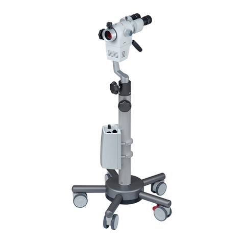
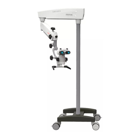
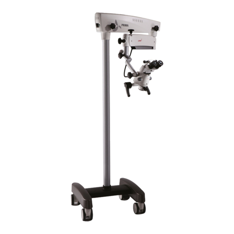
Labomed PRIMA ENT User manual

R
To ensure proper use of this instrument and to avoid injury during operation, reading this manual before use is highly
recommended.
PRIMA ENT/DNT
User Manual
Operating Surgical Microscopy
6137000-795 PRIMA ENT/DNT Issue 1.4
Printed March, 2016

2
Prima ENT/DNT
Prima ENT/DNT is a trade name for LABOMED Products.
LABOMED is a registered trademark of Labo America, Inc.
All other trademarks are the property of their respective owners.
The information contained in this document was accurate at the time of publication. Specifications
are subject to change without notice. LABOMED reserves the right to make changes to the product
described in this user manual without notice and without incorporating those changes in any
products already sold.
ISO 9001/13485 Certified – LABOMED products are designed and manufactured under quality
processes that meet ISO 9001/13485 requirements.
No part of this publication may be reproduced, stored in a retrieval system, or transmitted in any
form or by any means: electronic, mechanical, recording, or otherwise, without the prior written
permission from LABOMED.

3
Prima ENT/DNT
1. Introduction and Intended Use 4
2. Product Description 5-6
3. Warnings and Cautions 7-8
4. Explanation of Symbols 9
5. Standards and Directives 10
6. Unpacking 11
7. Installation Instructions
- 7A Installation of Base (Mobile Stand) 12-13
- 7B Microscope Installation 14-15
8. Electrical Connections
- Replacing the Illumination Source 16
- Replacing the Fuse 16
- Data Plate Details 16
- Prima Wiring Coding Diagram 17
9. Control Elements 18
10. Using the Microscope 19-20
11. Changing the Objectives and Eyepieces 21
12. Use of Accessories 22-23
13. Thermal Cut-Off 24
14. Tension Adjustment 24
15. Moving the Instrument 25
16. Care and Maintenance 26-27
17. Ambient Requirements 28
18. Disposal 29
19. Troubleshooting Table 30-31
20. Technical Specifications 32
21. Guidance Tables 33-36
22. Dimensions and Weight 37
23. Glossary 38
24. Warranty 39
List Of Contents

4
Prima ENT/DNT
LABOMED Prima ENT/DNT is a surgical and diagnostic microscope that is adaptable for different
surgical needs for consistent visualization during all intraoperative phases of ENT and dentistry
surgeries by providing a magnified view of the surgical field without compromising performance.
The microscope provides extremely high optical image quality, good depth of focus, and a wide field
of view for precise surgery.Illumination control and high eye point of the observation head helps
reduce the user’s work fatigue and allows comfortable use over a long period.
Salient features of this microscope are:
1. The observation head can easily be positioned with the help of a suspension arm.
2. An advanced 5-step magnification changer allows optimal magnification for various needs at
five different magnification levels.
3. Cold light illumination with a high-intensity 50W LED lamp is provided using a fiber optic
guide for proper illumination. Illumination can be adjusted using the intensity control knob
conveniently located at the suspension arm and easily accessible to the user.
4. When the microscope is not in use, the suspension arm can be folded over the main body for
compact storage.
5. The rigid H-shape base with caster wheels provides the instrument with stability and
mobility.
Intended Use
The Prima ENT/DNT microscope is an AC powered device intended for use during diagnosis and
surgery to provide a magnified view of the region of interest.
NOTE: Use Prima ENT/DNT microscopes as specified in the intended use.
Configurations
Microscope Catalogue no.
Prima ENT 6137000-000
Prima DNT 6138000-000
INTRODUCTION AND INTENDED USE
1

5
Prima ENT/DNT
PRODUCT DESCRIPTION
2
6
24
25
3
22
23
13 4
7
511
19
14
15
20
17
16
18
12 10
8
21
9
1
Prima DNT
1. Wheel with brake 14. Ergo Head 0-210° adjustable
2. H shape metal base 15. Magnification changer (magnichanger)
3. Column 16. Handles
4. Swivel arm 17. Common main objective (CMO)
5. Suspension arm 18. Magnichanger inclination
6. Swivel arm locking knob movement lock
7. Suspension arm movement locking knob 19. Illumination control knob
8. Coupling movement locking knob 20. Fine focusing knob
9. Inclined coupling 21. iVu Camera inlet
10. Inclined coupling movement knob 22. On/Off switch
11. Suspension arm hydraulic movement lock 23. Power inlet
12. Suspension arm spring tension adjustment 24. Eyepieces
13. Swivel arm covers 25. Counter balancing knob

6
Prima ENT/DNT
6
26
13 4
7
511
19
22
14
15
21
17
16
18
10
8
12
24
23
3
2
1
20
925
Prima ENT
1. Wheel with brake 14. Binocular head
2. H shape base 15. Magnification changer
3. Column 16. Handles
4. Swivel arm 17. Common main objective (CMO)
5. Suspension arm 18. Magnichanger inclination movement lock
6. Swivel arm locking knob 19. Illumination control knob
7. Suspension arm movement locking knob 20. Foot pedal for Z-axis (optional)
8. Coupling movement locking knob 21. Fine focusing knob
9. Inclined coupling 22. iVu Camera inlet
10. Inclined coupling movement knob 23. On/Off switch
11. Suspension arm hydraulic movement lock 24. Power inlet
12. Suspension arm spring tension adjustment 25. Eyepieces
13. Swivel arm covers 26. Counter balancing knob

7
Prima ENT/DNT
WARNINGS AND CAUTIONS
3
LABOMED is not responsible for the safety and reliability of this instrument when:
- Assembly, disassembly, repair, or modification is made by unauthorized dealers or persons.
- The instrument is not used in accordance with this user manual.
A WARNING is an instruction that draws attention to the risk of injury or death.
WARNING:USERS OF THIS EQUIPMENT SHOULD BE THOROUGHLY TRAINED IN THE APPROPRIATE
MEDICAL PROCEDURES. FURTHERMORE, THEY SHOULD TAKE THE TIME TO READ AND
UNDERSTAND THESE INSTRUCTIONS BEFORE PERFORMING ANY PROCEDURE. THEY SHOULD
ALSO READ AND UNDERSTAND THE INSTRUCTIONS FOR ANY OTHER EQUIPMENT USED IN
CONJUNCTION WITH THIS MICROSCOPE (i.e. ELECTROSURGICAL GENERATORS). FAILURE TO
DO SO MAY RESULT IN INJURY TO THE PATIENT AND/OR DAMAGE TO THE MICROSCOPE.
WARNING:THIS INSTRUMENT SHOULD BE USED IN STRICT ACCORDANCE WITH THE INSTRUCTIONS
OUTLINED IN THIS USER MANUAL. THE SAFETY OF THE OPERATOR AND THE PERFORMANCE
OF THE INSTRUMENT CANNOT BE GUARANTEED IF USED IN A MANNER NOT SPECIFIED BY
LABOMED.
WARNING:DO NOT REPAIR OR SERVICE THIS INSTRUMENT WITHOUT AUTHORIZATION FROM THE
MANUFACTURER. ANY REPAIR OR SERVICE TO THIS INSTRUMENT MUST BE PERFORMED BY
EXPERIENCED PERSONNEL OR DEALERS WHO ARE TRAINED BY LABOMED, OR SERIOUS
INJURY TO THE OPERATOR OR PATIENT MAY OCCUR.
WARNING:MODIFICATIONS TO THIS INSTRUMENT ARE NOT ALLOWED. ANY MODIFICATION TO THIS UNIT
MUST BE AUTHORIZED BY LABOMED, OR SERIOUS INJURY TO THE OPERATOR OR PATIENT MAY
OCCUR.
WARNING:IF THIS INSTRUMENT IS MODIFIED, APPROPRIATE INSPECTION AND TESTING MUST BE
CONDUCTED TO ENSURE CONTINUED SAFE USE OF THIS INSTRUMENT.
WARNING:TO AVOID RISK OF ELECTRIC SHOCK, THIS EQUIPMENT MUST ONLY BE CONNECTED TO A
SUPPLY MAIN WITH PROPER EARTHING, OR DAMAGE TO THIS INSTRUMENT AND/OR INJURY TO
THE OPERATOR OR PATIENT MAY OCCUR.
WARNING:ENSURE THAT THE VOLTAGE APPLIED TO THE UNIT IS THE SAME AS THE VOLTAGE INDICATED
ON THE DATA PLATE, OR DAMAGE TO THE UNIT MAY OCCUR.
WARNING:THIS INSTRUMENT MUST BE PLUGGED IN TO AN OUTLET WITH AN EARTH GROUND. DO NOT
REMOVE OR DAMAGE THE EARTH GROUND CONNECTION ON THE POWER INPUT
CONNECTOR OR THE UNIT’S POWER CORD, OR DAMAGE TO THE INSTRUMENT AND/OR INJURY
TO THE OPERATOR OR PATIENT MAY OCCUR.
WARNING:THE EQUIPMENT OR SYSTEM SHOULD NOT BE USED ADJACENT OR STACKED WITH OTHER
EQUIPMENT LIKE MRI MACHINES, RFID, SECURITY SYSTEMS LIKE METAL DETECTORS, OR
SIMILAR DEVICES. IF ADJACENT OR STACKED USE IS NECESSARY, THE EQUIPMENT OR SYSTEM
SHOULD BE OBSERVED TO VERIFY NORMAL OPERATION IN THE CONFIGURATION IN WHICH IT
WILL BE USED.
8
Prima ENT/DNT
WARNING: THIS INSTRUMENT IS NOT SUITABLE FOR USE IN THE PRESENCE OF FLAMMABLE ANESTHETIC
MIXTURES SUCH AS OXYGEN OR NITROUS OXIDE.
WARNING: LED RADIATION - DO NOT STARE DIRECTLY INTO THE BEAM WHEN THE MICROSCOPE IS IN THE
ON POSITION.
WARNING: THE USE OF ACCESSORIES OR CABLES OTHER THAN THOSE SPECIFIED, WITH THE EXCEPTION
OF THOSE SOLD BY THE MANUFACTURER AS REPLACEMENT PARTS FOR THE INTERNAL
COMPONENTS, MAY RESULT IN INCREASED EMISSIONS OR DECREASED IMMUNITY OF THE
EQUIPMENT OR SYSTEM.
A CAUTION is an instruction that draws attention to the risk of damage to the product.
CAUTION: THE INTERNAL CIRCUITRY OF THE INSTRUMENT CONTAINS ELECTROSTATIC SENSITIVE
DEVICES (ESD) THAT MAY BE SENSITIVE TO STATIC CHARGES PRODUCED BY THE HUMAN BODY.
DO NOT REMOVE THE COVERS WITHOUT TAKING PROPER ESD PRECAUTIONS.
CAUTION: DO NOT USE SOLVENTS OR STRONG CLEANING SOLUTIONS ON ANY PART OF THIS
INSTRUMENT, AS DAMAGE TO THE UNIT MAY OCCUR. SEE THE CARE AND MAINTENANCE
SECTION FOR DETAILED CLEANING INSTRUCTIONS.
CAUTION: MEDICAL ELECTRONIC EQUIPMENT NEEDS SPECIAL PRECAUTIONS WITH RESPECT TO
ELECTROMAGNETIC CHARGE (EMC) AND NEEDS TO BE INSTALLED AND SERVICED ACCORDING
TO THE EMC INFORMATION PROVIDED IN THE ACCOMPANYING DOCUMENTS.
CAUTION: PORTABLE AND MOBILE RF COMMUNICATIONS EQUIPMENT CAN AFFECT MEDICAL
ELECTRICAL EQUIPMENT.
CAUTION: THIS INSTRUMENT IS NOT TO BE USED NEAR HIGH-FREQUENCY EMITTING SURGICAL
EQUIPMENT.
CAUTION: DO NOT CONNECT ANY EQUIPMENT TO THE DEVICE OTHER THAN THOSE INTENDED FOR USE
WITH THE DEVICE.
CAUTION: DO NOT USE A CONVERTER ADAPTER THAT WILL CONVERT THE THREE-PRONG AC PLUG TO A
TWO-PRONG LINE PLUG. THE POWER SUPPLY IN THIS MICROSCOPE WILL NOT BE PROPERLY
GROUNDED, AND ELECTRIC SHOCK MAY RESULT.
CAUTION: REMOVE THE AC POWER PLUG FROM THE WALL SOCKET WHILE CHECKING FOR A BLOWN
FUSE.
CAUTION: DO NOT ROLL THE MICROSCOPE OVER CABLES OR HOSES.
CAUTION: DO NOT REMOVE FERRITE BEADS IF APPLIED TO CABLES.

9
Prima ENT/DNT
Caution: Observe all warning labels and notes! If any label is missing on your instrument or
has become illegible, please contact the manufacturer to obtain new labels.
Brightness control: After the illumination has been switched on, the user can continuously
adjust brightness by turning the appropriate knob.
Accompanying documents must be consulted.
Compliance to medical device directive 93/42/EEC.
Protective earthing
This way up - indicates the correct upright position of the transport package.
Keep dry - the transport package shall be kept away from rain.
Year of manufacture used on product data plate.
Fragile - contents of the transport package are fragile and should be handled with care.
Electromagnetic interference can occur in the vicinity of devices carrying this symbol.
Alternating Current
Permissible humidity range during transport and storage.
Permissible pressure range during transport and storage.
Recycling of packaging materials.
The product complies with US and Canadian safety requirements.
Permissible temperature range during transport and storage.
Separate disposal of waste electrical equipment.
Unsafe for use with MR (Magnetic Resonance).
Do not over balance more than 5°.
EXPLANATION OF SYMBOLS
4

10
Prima ENT/DNT
STANDARDS AND DIRECTIVES
5
The instrument described in this user manual has been designed in compliance with the
following standards:
·ISO 8600-3 First edition 1997-07-01 AMENDMENT 1 Optics and Optical instruments-
Medical endoscopes and endoscopic accessories Part 3: Determination of field of view
and direction of view of endoscopes with optics.
· ISO 8600-3 First edition 1997-07-01 Optics and Optical instruments-Medical
endoscopes and endoscopic accessories Part 3: Determination of field of view and
direction of view of endoscopes with optics.
·ISO 8600-5 First edition 2005-03-15 Optics and photonics-Medical endoscopes and
endotherapy devices Part 5: Determination of optical resolution of rigid endoscopes
with optics.
· ISO 9001/13485 Quality management systems approved by UL (notified body).
· ISO 14971-2007 Risk management to medical devices.
Directives Used
·Directives 93/42/EEC, Article II, Section 5, Annex VII
·IEC 60601-1-3rd edition (2005)
·IEC 60601-1-2
·EN 55011:2007
Classifications
· For Europe, per Directive 93/42/EEC, the unit is a Class I instrument, per rule 12,
Annex IX.
· For the United States, the FDA classification is Class I.
· Please observe all applicable accident prevention regulations.

11
Prima ENT/DNT
UNPACKING
6
The appliance is delivered in sub-assembled groups along with one Installation Kit and one
user manual.
Please check for the following when unpacking the device:
1. Mobile supporting base with brakes on caster wheels or other type of mounting
2. Column, depending on the type of mount ordered
3. Swivel arm and suspension arm assembly with fiber optic cable
4. Inclined coupling with magnichanger assembly and common main objective with
focal length as ordered
5. Observation head (straight or ergo tiltable 0-210°) as ordered
6. Pair of eyepieces as ordered
7. Power cord
8. Installation Kit
a) Allen wrench 5 mm
b) Allen wrench 8 mm
9. User manual

12
Prima ENT/DNT
INSTALLATION OF BASE (MOBILE STAND)
7A
1. Open the Center Support assembly box
as shown in Fig. 1.
2. Remove the tool kit and foam sheets as
shown in Fig. 2.
3. Lift up the Center Support assembly as
shown in Fig. 3.
4. Place the Center Support assembly on
the floor as shown in Fig. 4.
5. Open one of the Wheel Support
assembly boxes as shown in Fig. 5.
6. Remove foam sheets as shown in Fig. 6.
Fig 1
Fig 2
Fig 3
Fig 4
Fig 5
Fig 6

13
Prima ENT/DNT
7. Lift the Wheel Support assembly
and cover as shown in Fig. 7. Place it
(wheels down) under one end of the
Center Support as shown in Fig 8.
Repeat procedure for the other Wheel
Support assembly.
8. Align holes of the Center Support with
the holes of both Wheel Supports and
tighten the screws as shown in Fig. 8
using the 8 mm allen wrench.
9. Remove 2 screws at center as shown
in Fig. 9 to remove the wooden block.
Unscrew with screw driver as shown in
Fig. 9.
10. Remove the wooden block as shown in
Fig. 10.
11. Tighten all screws using the 8 mm allen
wrench.
12. Place top cover on both Wheel Support
assemblies as shown in Fig. 12.
Fig 7
Fig 8
Fig 9
Fig 10
Fig 11
Fig 12

14
Prima ENT/DNT
A
D
B
3
2
1AB
1. Open the microscope box. Remove pillar (column)
from the box. Engage this column to the base
through indexing pin, shown as B in Fig 2. Align
the tapped holes of the column with the base and
tighten two allen screws from the bottom, shown
as A in Fig 2.
2. Make sure that during assembly of the column,
ring (D) is fixed in place, as shown in Fig 2.
3. Remove the arm assembly from the box and
follow the instructions below (see Fig. 3).
A. Ensure that the swivel arm lock knob (A) is
loosened.
B. Place the arm assembly on the column shaft
(1) shown in Fig. 3.
C. Screw in the threaded plug from the top (2).
D. Put the protective cap (3) in place, and loosen
the suspension arm locking knob (B) so that it
can be rotated.
Do not unscrew knob A completely (see Fig. 3).
Loosen only a few threads; otherwise the lock
ring inside the column guide may disconnect and
installation may not possible.
Fig 2
Fig 3
MICROSCOPE INSTALLATION
7B

15
Prima ENT/DNT
4. Remove the inclined coupling assembly from its
packaging and follow the instructions below (see
Fig. 4.)
A. Install the coupling by sliding the shaft (1)
into the suspension arm.
B. Lock the inclined coupling with the threaded
knob (3).
C. Make sure the safety screw is installed and
tightened at position (2) so the coupling
does not detach if knob (3) is accidentally
unscrewed.
5. Mount the light guide by completing the steps
below.
A. Switch off the illumination system.
The light guide comes pre-routed through
the swivel arm (which houses the LED
illumination system) and the suspension arm.
B. Remove the dust cap from the receptacle.
C. Insert the light guide into the receptacle in
the microscope until it clicks into position as
shown in A in Fig. 5.
D. Make sure the light guide has been routed
in such a way that the carrier system and
the surgical microscope are not obstructed
and can be moved in their entire range of
movement without stretching, kinking, or
twisting the light guide.
6. Install the binocular head and eyepieces on the
magnichanger. Secure the binocular head with
the head locking screw as shown in A in Fig. 6.
Fig 4
Fig 5
Fig 6
3
1
2
Safety Screw
A
A

16
Prima ENT/DNT
ELECTRICAL CONNECTIONS
8
1
2
3
A
ON/OFF Switch
A/C Inlet
Connect the power cable to the AC inlet socket (1)
located at the back of the swivel arm (see Fig. 7).
Switch on the power using the on/off switch (2).
Note: The power supply is designed with universal input
100V-240V AC, 50/60Hz. To plug in the power supply,
follow the instructions on the electrical label located at
the bottom of the arm (see 3 in Fig. 7).
1. Replacing the Illumination Source
A. Detach the swivel arm covers.
B. Detach the fiber optic cable and replace the
illumination assembly (see A in Fig. 8) with a
new assembly.
C. Resecure the arm covers.
2. Replacing the Fuse
A. Locate the fuse at the AC inlet (see Fig. 9).
B. Use a flat head screw driver to open the fuse
compartment. Two fuses are provided: one is
a live fuse and the second is a spare fuse.
C. Replace the blown fuse with the spare fuse
and close the fuse compartment.
For fuse replacement, refer to the label shown in
Fig. 9.
3. Data Plate Details
UL Mark
Safety Certification Accompanying Document
Must Be Consulted
IEC60601-1:2005
Labeling for USA and Europe
IEC60601-1:2005
Labeling for Canada
Label Control
Number
Fuse Rating
Company
Trademark
ManufacturerSeparate Disposal
Waste Electric Device
Device Name
Model Number
Serial Number
Input Voltage
Frequency
Max Load
Fig 7
Fig 8
Fig 9

17
Prima ENT/DNT
PRIMA WIRING CODING DIAGRAM

18
Prima ENT/DNT
CONTROL ELEMENTS
9
1. ON/OFF Switch (see 2 in Fig. 7)
The ON/OFF switch is located at the back of the swivel
arm. In the ON position, a green LED glows, and the
cooling fan starts running. Set the intensity control knob
at the minimum intensity level before switching the
system on.
To preserve the life of the LED, turn off the instrument
when the microscope is not in use.
2. Intensity Control Knob
This knob is located at the front of the suspension arm
(see A in Fig. 10). The brightness of the field of view can
be adjusted as desired using the intensity control knob.
3. Swivel Arm Locking Knob
This knob (see B in Fig. 10) locks the movement of the
swivel arm at the desired position by turning it clockwise.
4. Brakes
Lock the stand to prevent unwanted movement by
pressing down on the two brakes provided on the caster
wheels (see Fig. 11). To unlock, press upward on the
brakes.
5. Adjusting Tension on Carrier Rotation
If any optional accessories are added to the microscope,
the tension on the carrier rotation must be adjusted to
compensate for the added weight by completing the
steps below.
A. Unscrew the black cap (see 1 in Fig. 12).
B. Use a 19 mm wrench to turn the screw (see 2
in Fig. 12) to achieve the desired tension.
C. Once the desired tension is achieved, screw
on the black cap (see 1 in Fig. 12).
Fig 10
Fig 11
Fig 12
BA
2
1

19
Prima ENT/DNT
Tension
Adjustment Screw
IPD Knob
(A)
14a
14b
Setting Up the Microscope
1. For stability, lock both brakes on the caster
wheels.
2. Tension in the up and down motion of the
microscope is preset at the factory. However, the
user can adjust the force required to move the
microscope up and down by turning the Tension
Adjustment Screw (see Fig. 13) clockwise or
counterclockwise using an 8 mm allen wrench.
Refer to section 14 for more details.
3. Lock the up and down movement of the
suspension arm using the locking knob (see B
in Fig. 10 above) after focusing on the area of
interest.
4. Adjust the interpupillary distance (IPD) of the
eyepieces as needed, using the IPD adjustment
knob.
5. The illumination is controlled through the
intensity control knob (see A in Fig. 13). Rotate
it clockwise or counterclockwise to achieve the
desired illumination level.
Setting Up Magnification (See Fig. 14)
1 Use the rotating knobs (14a) provided on the
magnification changer to select the desired
magnification level.
2 Use the fine focusing knob or foot pedal to achieve
fine focus.
3 Use the manual handle (14b) to center the area of
interest in the field of view.
Fig 13
Fig 14
WARNING: INSTRUMENT IS UNSAFE FOR MRI ENVIRONMENTS.
USING THE MICROSCOPE
10

20
Prima ENT/DNT
Make sure that the magnification changer is engaged at
a click stop position (not between click stops).
Main Microscope
Objective lenses with focal lengths of 250 mm, 300
mm, 400 mm, or variable working distance are avail-
able, depending on the user’s desired working distance.
A straight binocular head (Prima ENT) or ergo/tilting
binocular head (Prima DNT) is provided.
Standard configurations include eyepieces with a
magnification factor of 10x (12.5x eyepieces are
optional). Fig 15
Other manuals for PRIMA ENT
1
This manual suits for next models
1
Table of contents
Other Labomed Medical Equipment manuals

Labomed
Labomed Prima OPH User manual

Labomed
Labomed eVO 300 User manual

Labomed
Labomed Prima C User manual

Labomed
Labomed eVA 500 User manual

Labomed
Labomed Prima C User manual

Labomed
Labomed PRIMA GN User manual

Labomed
Labomed Pixel Pro 3.2 User manual

Labomed
Labomed eVO 350 User manual

Labomed
Labomed AXIUS User manual

Labomed
Labomed PRIMA WALL MOUNT Guide