LABORIE PORTASCAN 3D User manual

LABORIE Portascan3D Service Manual PTS3D-SM01 V3.0
PORTASCAN 3D
Service Manual

LABORIE Portascan3D Service Manual PTS3D-SM01 V3.0
USA
400 Avenue D, Suite 10
Williston, Vermont, USA 05495
Tel: 1.800.522.6743
Fax: 1.802.878.1122
usmarket[email protected]
HEADQUARTERS
6415 Northwest Dr., Unit 11
Mississauga, Ontario, Canada
L4V 1X1
Tel: 905.612.1170
Fax: 905.612.9731
marketing@laborie.com
EUROPE/INTERNATIONAL
P.O. Box 580
7500 AN Enschede
The Netherlands
Tel.: +31.53.4803700
Fax: +31.53.4803701
info@laborie.com
Document Number: PTS3D-SM01
Version: 3.0
Release Date: September 1, 2016
MAN1027
Shanghai International Holding Corp. GmbH (Europe)
Eiffestrasse 80, 20537 Hamburg, GERMANY
Tel: +49-40-2513175 Fax: +49-40-255726
E-mail: shholding@hotmail.com
Manufactured by MEDA CO., LTD F2C, F3D, F4C, F5;
Building C2, Xinmao Science Skill Park, Huayuan Industry
Development Area, 300384, Tianjin, CHINA for
LABORIE MEDICAL TECHNOLOGIES CANADA ULC
6415 Northwest Drive, Unit 10,
Mississauga Ontario L4V 1X1 Canada

LABORIE Portascan3D Service Manual PTS3D-SM01 V3.0 i
Table of Contents
1. STRUCTURE OF THE PRODUCT ..................................................... 1
2. PRINCIPLE OF OPERATION.......................................................... 3
3. UNIT QUALITY INSPECTION ......................................................... 4
3.1 ACCURACY............................................................................. 4
3.2 FUNCTIONS.............................................................................. 4
3.3 APPEARANCE ......................................................................... 4
4. COMMON FAULTS AND TROUBLESHOOTING ............................ 5
4.1 POWER SWITCH ...................................................................... 5
4.2 PROBE ...................................................................................... 6
4.3 DISPLAY.................................................................................... 8
4.4. CLOCK .................................................................................. 12
4.5 PRINT....................................................................................... 12
4.6 BATTERY.................................................................................. 13
5. CALIBRATION & VERIFICATION................................................ 14
5.1 TOUCH SCREEN CALIBRATION ........................................... 14
5.2 PROBE VERIFICATION........................................................... 14
6. DISASSEMBLY OF THE MAIN UNIT............................................. 14
6.1 DISASSEMBLY TIPS ................................................................. 19
6.2 MAIN COMPONENT LAYOUT .............................................. 20
7. CLEANING & MAINTENANCE ................................................... 21
7.1 CLEANING MAIN UNIT ......................................................... 21
7.2 CLEANING THE PROBE ......................................................... 21
7.3 ROUTINE MAINTENANCE ..................................................... 23
8. CONNECTIONS ON MAIN BOARD........................................... 23
9. ADVANCED SERVICE ................................................................ 24
9.1 SYSTEM DEFAULT SETTINGS .................................................. 24
9.2 DISPLAY UNIT ......................................................................... 27
9.3 MAIN BOARD ........................................................................ 30
9.4 PROBE VERIFICATION & CALIBRATION.............................. 32
10 DOCUMENTATION AND RECORDS ......................................... 38


LABORIE Portascan3D Service Manual PTS3D-SM01 V3.0 1
1. STRUCTURE OF THE PRODUCT
The components of Portascan 3D are shown in Table 1.
TABLE 1: STRUCTURE AND FUNCTION DESCRIPTION
NO.
PARTS NAME
FUNCTION DESCRIPTION
1
Digital Part of Mainboard
Consisting of CPU, RAM, Crystal
Oscillator, ADC, DAC and
peripheral circuit to achieve
software operation, system control,
data acquisition, imaging, bladder
intellectual recognition, battery
power management and volume
measuring algorithm etc.
2
Analog Part of Mainboard
Consisting of pulse transmission
circuit, echo receiving and
magnification circuit to achieve
ultrasound pulse transmission, echo
receiving, magnification and
processing functions.
3
Battery Interface Board
For connecting the battery to the
power input of the main board.
4
Key Switch Board
For initiating the main unit power
5
3D Ultrasound Probe
Consisting of 2.5 MHz transducer,
two step-motor, mechanical
transmission mechanism, probe
housing and cable. The slave motor
drives the ultrasound transducer to
do 120° sector scanning; the main
monitor is used to drive the 180°
axial rotating of the motor and
ultrasound transducer and then
realize 3 dimensional scanning.
6
Thermal Printer
For data and images printing
output
7
LCD Monitor and Inverter
To display human-computer
interface, ultrasound image of

2LABORIE Portascan3D Service Manual PTS3D-SM01
V3.0
NO.
PARTS NAME
FUNCTION DESCRIPTION
bladder section, bladder projection
drawing and bladder volume.
8
Touch Screen and
Controller
Operation interface control and
realizing HCI
9
Lithium Battery Charger
Recharging the lithium battery
10
Lithium Battery
Providing power for the system,
3000mAH capacity and more than
300 recharging cycles.
11
Shielding Case
Shielding measure for EMC test
12
Housing Case
ABS injection housing case
Connecting cables between the electronic units are shown in Table 2.
TABLE 2 CONNECTING CABLE LIST
NO.
CABLE DESCRIPTION
NOTES
1
Power cable between
battery interface board
and digital part of the
mainboard
Line to Line plus in red and black
2
Probe socket connecting
cable
4-pin plug on the mainboard
3
LCD data cable
2x20 double row plug, connecting
with LCD
4
LCD Back light unit control
cable
6-pin flat cable plug
5
Thermal printer
connecting cable
5-pin plug
6
Power indicator
connecting cable
4-pin plug
7
Touch screen control
cable
4-pin plug
8
Power switch connecting
cable
2-pin plug
9
Motor control cable
8-pin plug
10
USB connecting cable
5-pin plug

LABORIE Portascan3D Service Manual PTS3D-SM01 V3.0 3
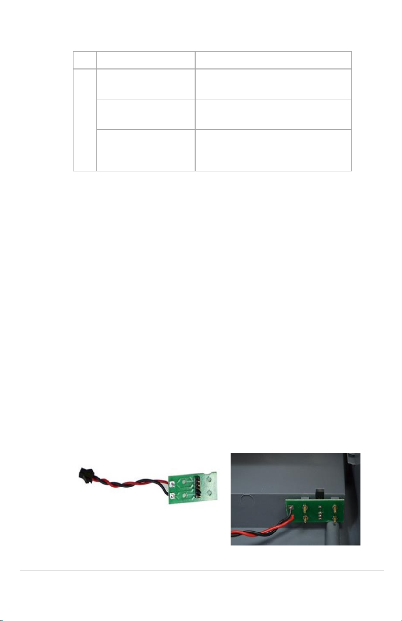
NOTE: Please refer to
Fig. 8
for the cable connection.
2. PRINCIPLE OF OPERATION
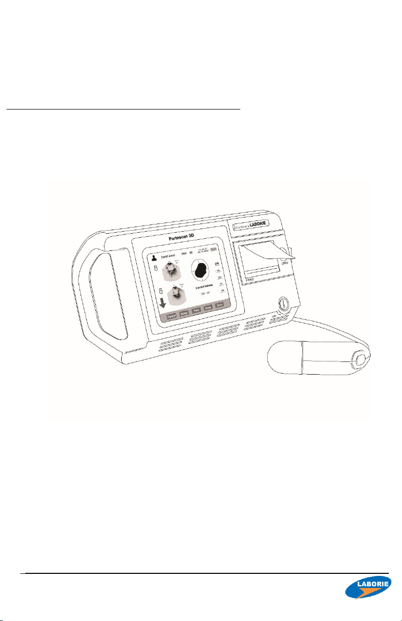
The main parts of the product include main board, LCD, touch screen,
3D ultrasound probe, thermal printer and rechargeable lithium battery.
The operation principle is describe in Fig.1.
3D ultrasound probe consists of 2.5 MHz transducer, two step-motor,
mechanical transmission mechanism, probe housing and cable. The
slave motor drives the transducer to do 120°sector scanning. Main
motor drives the motor and transducer to do 180°axial rotating. Then
3D scanning is achieved.
The transducer emits ultrasound wave into the human body with
excitation of electric pulse and then receives the reflected signals from
the bladder. The urine inside the bladder is low echo area and forms
strong reflection at the wall of the bladder. Amplitude discrimination
method can easily help to recognize the reflected waves at the
bladder anterior and posterior walls and then calculate the distance
between the two walls. Cross section area can be calculated with
integral calculation method after the scanning is obtained. Then
control signal is emitted for 15°rotation of the main monitor and then
the scanning for next cross section is initiated. The bladder volume can
be calculated with integral calculation method after the scanning of
the 12 cross sections is finished.
To guarantee the correct probe location, pre-scanning function is
designed to show the ultrasound image of the bladder. Users may
adjust the position of probe to make sure that the whole bladder is
within the sector scanning area, and then start scanning. A measuring
result can be obtained based on these steps.
The product utilizes lithium battery for power supply considering the
operation requirements of ward. To ensure that the product can work
continuously for enough long time, economical and effective power
consumption was thoroughly considered when power management
circuit was designed. When the product has not been operated for a
long time after switching on, the LCD back light will be switched off
automatically. Automatic Power-off function is also designed to
effectively utilize battery power.
Measuring result output can be achieved through thermal printer or
inner memory.

4LABORIE Portascan3D Service Manual PTS3D-SM01
V3.0
3. UNIT QUALITY INSPECTION
3.1 ACCURACY
A phantom is used to test the accuracy of volume readings.
Inside the phantom is a simulated bladder with a volume
mentioned on each unit.
Take 5 scans and check if the highest and lowest one from the
5 readings are within the tolerance.
Caution! Please tune the gain value up to 40dB when being
inspected on the phantom, and tune the gain value back down
to 20dB after the inspection!
NO.
REQUIREMENTS
REMARKS
1
Tolerance ≤±15%
40 dB Gain on Phantom
20 dB Gain on Human
3.2 FUNCTIONS
Test each function in routine operations according to the user’s
manual.
In this test item, we focuses on touch screen button, probe
button, interface display and printing.
NO.
REQUIREMENTS
REMARKS
2
Touch Screen Button
Probe Button
Interface Display
Printing
3.3 APPEARANCE
This test item is focused on color, text labeling, scratch marks
and spots.
Check whether plastic parts bubble, crack, deform or overflow,
whether operational and adjustment mechanisms are flexible
and secure, and whether fastening pieces are tightly fastened.

LABORIE Portascan3D Service Manual PTS3D-SM01 V3.0 5
NO.
REQUIREMENTS
REMARKS
3
Colour
Uniform colour, No scratches or spots,
clear and fast text labeling
Plastic Components
No bubbling, cracking, deformities or
overflowing
Operational &
Adjustment
Mechanisms
Flexible and secure, all components
tightly fastened
4. COMMON FAULTS AND
TROUBLESHOOTING
4.1 POWER SWITCH
Check if the battery is completely plugged into the slot and
locked, and check if the battery power is sufficient.
If the above is operated and no failure is detected, please
open the housing case following 6. DISASSEMBLY OF THE MAIN
UNIT, remove the shielding case and measure power input
voltage of the digital board. The normal reading should be
12V±5%.
1. If the voltage is abnormal, the problem may occur to the
battery interface board and corresponding measures
should be taken. The battery interface board connects
to the digital board power cable and battery, and is fixed
at the back housing case with 4 screws (shown in Fig.4.1).
Afterwards, please remove the battery interface board
for checking or replacing.
Fig. 4.1 Battery Interface Board Position Sketch Map

6LABORIE Portascan3D Service Manual PTS3D-SM01
V3.0
2. If the voltage is normal, the problem may occur on the
mainboard. This problem may be judged by substitution
method. If problem with the digital part is identified, then
the mainboard should be replaced.
4.2 PROBE
A. Physical Probe Issues
1. If the probe cracks and leaks oil, send it back to Service
Center or the Manufacturer for further repair or
replacement. Do not try to repair on your own.
Fig. 4.2.: Probe cracking
2. If the probe’s rubber ring deteriorates, breaks, or is
missing replace it with a new one. To restore the seal of
the rubber ring, secure with a rubber based glue. If you
are unable to do so, send it back to the Service Center
or Manufacturer for further repair or replacement.
3. If the probe’s motor doesn’t vibrate or work properly
send it back to Service Center or the Manufacturer for
further repair or replacement. Do not try to repair.
B. Probe Button Malfunction
If there is no response when pressing the probe button:

LABORIE Portascan3D Service Manual PTS3D-SM01 V3.0 7
1. Make sure that the probe and the main unit are well
connected and then click “SCAN” key on the main
interface. If the probe can work normally, the problem
may occur to the probe. Please identify the problem
with substitution method and replace the probe when
necessary.
2. If the above measure does not work, please open the
housing, remove the shielding cover and check probe
socket connecting cable. Identify the problem with
substitution method and replace the connecting cable
when necessary.
3. If the above measures do not work, the problem may
occur to main board. Please identify the problem with
substitution method and replace the main board when
necessary.
C. No Information is displayed when Probe Scans
1. Check if the probe cable is connected well with the
probe socket. If the probe is well connected, so
scanning with a normal probe. If there is a signal, the
problem with the probe can be identified. The probe
should be replaced to solve the problem.
2. If the replacing probe still produces no signal, then
please open the housing case, remove the shielding
case and check the signal cable at the soldered side
of the analog board and probe socket connecting
cable. If the problem is identified with substitution
method, please replace the connecting cable to solve
the problem.
3. If procedures 1. and 2. do not solve the problem,
please check if the connecting cable (shown in Fig. 8)
is well connected and identify the problem with the
substitution method. Replace the connecting cable
when necessary.
4. If the above-mentioned measures do not work, the
problem may be with the main board. Please identify
the problem with substitution method and replace the
main board if necessary.

8LABORIE Portascan3D Service Manual PTS3D-SM01
V3.0
D. Probe Scan shows only a vertical line
If you have another probe, use it for test.
1. If system comes back to normal, this indicates that the
probe with no image had signal transmission
interruption. Please send the probe to the Service
Center for repair or cable replacement.
2. If probe is changed and the system still has no image,
this indicates that all system failed. Please send your
unit and probe together to the Service Center for repair.
3. If you do not have spare probe, please send unit and
probe together to the Service Center for repair.
E. Probe Connection Issues
Probe plug has a clip to lock the plug with the socket on the
unit. Insertion or removal needs to pull the unlock sleeve to right
to low the lock clip. If the plug is dirty, filled with dirt, gel, or oil, it
will be hard to connect or remove.
Fig. 4.3: Disassemble the plug and use 70% alcohol solution to
wash each component
4.3 DISPLAY
A. LCD Calibration
1. Check if there are irrelevant materials at the surrounding
area of the screen and clear them off if there is.
2. Calibrate the touch screen for trouble shooting. Touch
screen calibration guidance: Switch on the instrument
while pressing the probe button and operators will enter

LABORIE Portascan3D Service Manual PTS3D-SM01 V3.0 9
screen calibration interface.
Fig. 4.4 a) Touch Screen Calibration Interface
A cross mark appears after entering the touch screen
calibration program (shown in Fig. 4.4 a).
Reminder: Make sure to touch the surrounding area of
the cross.
Fig. 4.4 b) Touch Screen Calibration Interface
Fig. 4.4 b) shows the coordinates of LCD and
touchscreen and there will be a cross at the lower right
corner of the screen. Please touch the surrounding
area of the cross with the above-mentioned method.
Based on the theory that two points makes one line, the
corresponding relationship between the touch screen
and LCD can be identified. Then operators may select
the third point for verification, which is shown by Fig. 4.4
c).
Fig. 4.4 c) Touch Screen Calibration Interface

10 LABORIE Portascan3D Service Manual PTS3D-SM01
V3.0
Fig. 4.4 d) Calibration Completed Interface
Fig. 4.4 e) Recalibration Interface
Fig.
4.4
c) shows the coordinates of LCD and touch
screen after second touching at the cross. Meanwhile,
the third cross, used for verification of calibration,
appears at upper right corner of the screen. Successful
calibration will lead to the interface of Fig.
4.4
d) and
then to main interface of the main unit. If the
calibration fails, the instrument will enter the interface
of
4.4
e) and returns to interface of Fig.
4.4
a) in a while.
Operators need to recalibrate the touch screen until
calibration succeeds to enter main interface.
3. If procedures 1 and 2 do not work, operators may check
the connecting cable between the touchscreen control
board, the touch screen, and the touchscreen control
cable to see if the cables are loose.
4. If the connecting cables are normal, please check the
touch screen controller with substitution method.
Replace the controller when necessary. Touch screen
controller is fixed at the printer cover with 2 screws and
can be removed by disassembling the connecting
cables and removing the two screws. (Fig.
4.4
f)

LABORIE Portascan3D Service Manual PTS3D-SM01 V3.0 11
Fig. 4.4 f) Removing touch screen controller
5. If replacing controller does not work, the problem may
have occurred to the digital part. Operators may identify
the problem with substitution method and replace the
main board if necessary.
B. Abnormal Display of LCD (color error, screen flash,
etc…)
Open the housing case following 6. DISASSEMBLY OF THE MAIN
UNIT, remove shielding case and check if the back light unit
control cable, LCD data cable are correctly and well plugged
(as shown in Fig. 8). Connect these cables properly to exclude
the problem.
1. If the above-mentioned procedure does not work,
operators may judge if problem occurs to the main board
with substitution method and replace the main board
when necessary.
C. No Display On LCD
1. Follow 6. DISASSEMBLY OF THE MAIN UNIT to open the
housing to remove the shielding case and check the LCD
back light board control cable. Replace the connecting
cable to solve the problem when necessary.
2. If the above-mentioned procedure does not work,
operators may judge if problem occurs to the main board
with Check the LCD data cable, and change the data
cable when necessary to exclude the problem.
3. Measure the voltage of back light control cable pin, and
check whether the voltage complies with the standards
listed in LCD manual.

12 LABORIE Portascan3D Service Manual PTS3D-SM01
V3.0
4. If the above-mentioned procedure does not work,
operators may judge if the problem occurs to the main
board with substitution method and replace the main
board when necessary.
4.4. CLOCK
A. Abnormal Clock Display, Clock Resetting Can’t
Be Saved
1. Open the housing case to remove the shielding case and
replace the clock battery on the main board to solve the
problem. The battery is a SONY CR2032 (3V Lithium
battery). Press the clip on the battery base and the old
battery will pop up. Operators may equip a new battery
at the battery base with the positive pole up and the
negative pole down.
2. If the setting still can’t be saved with the above measures,
operators may check if the battery base is well welded
and solve the problem accordingly.
4.5 PRINT
A. No Response When Pressing “Print”
1. Restart the instrument and there should be a mechanical
running sound with the printer when turning on. If no
sound is heard, operators may open the housing case,
remove the shielding case and check the thermal printer
power cable following
2. . Please replace the connecting cable when necessary.
3. If there is a printer running sound when the power is
turned on, but the printer still does not work, operators
may check the printer data cable (6), which is shown in
Fig. 8.
4. If there is a printer running sound, and the connecting
cables are normal but the printer does not work, the
problem can be the printer. Please check if the problem
occurs to the printer with the substitution method. The
printer consists of a printing head and a printer board,

LABORIE Portascan3D Service Manual PTS3D-SM01 V3.0 13
both of which are fixed at the printer cover. Remove the
4 screws following the below picture first and remove
another 2 screws to get to the printer board and printer.
Fig. 4.5 Disassembly of the Printer
5. If procedures of 1. and 2. do not detect any abnormality,
the problem may have occurred on the main board.
Operators may decide with substitution method and
replace the main board when necessary.
B. Thermal Paper Runs Normally But Not Printing
Information When Pressing “Print”
Check if the thermal paper is placed in the opposite direction
(thermal side facing up) and place the thermal paper correctly
to solve the problem.
4.6 BATTERY
A. Recharging Failure with the Lithium Battery
1. Power on the charger and measure the no-load voltage of
power output end with the digital multimeter and check if
the voltage is 12.6V±5%.
2. If no problem is detected from 1), the problem may occur
to the battery. Recharge the low power lithium battery and
observe if the charger indicator turns red. If the indicator
remains green, then problem occurs to the battery. Please
replace the battery to solve the problem.

14 LABORIE Portascan3D Service Manual PTS3D-SM01
V3.0
5. CALIBRATION & VERIFICATION
5.1 TOUCH SCREEN CALIBRATION
Refer to Section 4.3.A - LCD Screen Calibration
5.2 PROBE VERIFICATION
Probe is verified using a phantom bladder (BVL1004) at Gain 40
dB. The volume of the bladder is mentioned on its label ±15%.
Refer to Section 9.4 Probe Verification and Calibration for more
detailed procedure
6. DISASSEMBLY OF THE MAIN UNIT
STEP/ACTION
1
Remove the 8
screws to
separate the front
and back covers
of the housing
case, as shown
2
The shielding cover
has no screw
fixation, so it can be
removed or re-
mounted manually
with help of
tweezers

LABORIE Portascan3D Service Manual PTS3D-SM01 V3.0 15
STEP/ACTION
3
Disconnect all the
wires from the main
board manually or
using tweezers.
Caution: please
take appropriate
anti-static measures
before
disconnection.
4
Unscrew 4 screws
securing the main
board to remove
from main unit.
5
After the main
board is removed,
the remaining
components fixed
onto the front panel
are LCD and touch
screen, key switch
board, printer and
power indicator.

16 LABORIE Portascan3D Service Manual PTS3D-SM01
V3.0
STEP/ACTION
6
After the main
board is removed,
the remaining
components fixed
onto the rear panel
are battery
connector board
and USB board (at
right)
7
The USB board is
fixed by two screws
on the rear panel.
8
The battery
connector board is
fixed by 4 screws in
the battery slot on
the rear panel.
Caution: when you remount battery to the main unit, make sure the
second pin from the top is not the metal one. Failure to do so, i.e.,
putting it upside down, will cause the battery to fail.
Table of contents
Other LABORIE Diagnostic Equipment manuals