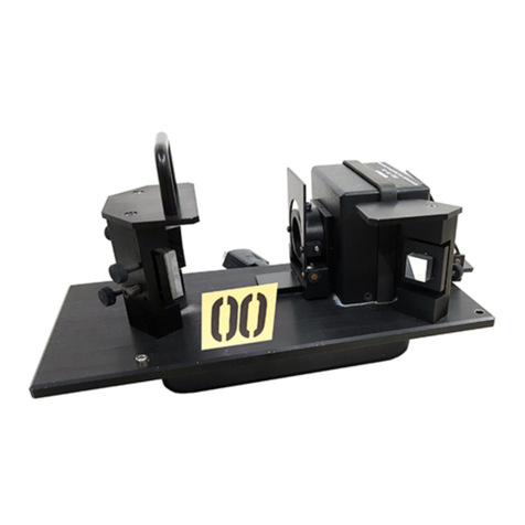
Labsphere DRA-CA-3300 User manual

AQ-00275-000, Rev. 3
DRA-CA-3300 Diffuse Reflectance Accessory
Introduction .............................................................................................................. 1
Unpacking and Inspection ....................................................................................... 3
Standard Components ....................................................................................3
Optional Components ....................................................................................3
Installation ................................................................................................................ 5
Optical Alignment of the Accessory ....................................................................... 8
Alignment Check ...........................................................................................8
Aligning the Accessory Optics ......................................................................9
Diagnostic Scans ..........................................................................................11
Operation ................................................................................................................ 14
Integrating Sphere ........................................................................................14
Optical Chamber ..........................................................................................15
Loading the Sample Reflectance Port ..........................................................15
Transmittance Sample Holder ......................................................................17
8°/Hemispherical Reflectance Factor Measurements .................................. 17
0°/Diffuse Reflectance Factor Measurements ..............................................18
Large Sample Reflectance Measurements ...................................................18
Transmittance Measurement Procedure .......................................................19
Theory of Operation .....................................................................................21
Double Beam Spectroscopy .........................................................................21
Reflectance Measurement of Non-Ideal Samples ........................................24
Zeroline Correction ......................................................................................26
Sources of Error ...........................................................................................26
Optional Components ............................................................................................ 28
Center Mount Sample Holders ....................................................................28
Powder Cell Holder ......................................................................................35
Transmittance Port Cuvette Holder ..............................................................37
Maintenance ........................................................................................................... 39
Mirror Cleaning Procedure ..........................................................................39
Spectralon Care Guide .................................................................................39
Troubleshooting the DRA-CA-3300 ............................................................40
Detector Replacement ..................................................................................41
Appendix A Specifications .................................................................................... 42
Appendix B Typical Spectralon Reflectance Factors ......................................... 43
Appendix C Glossary ............................................................................................ 44

AQ-00275-000, Rev. 3 1
Introduction
The traditional use of the spectrophotometer is to measure the transmittance of a clear or translu-
cent liquid or solid. Typical UV/VIS spectroscopy applications in this regard include reaction
kinetics, quantitative analysis or the simple identification of the chemical constituents in a sub-
stance. The measurement of reflectance offers an added dimension to the spectroscopy capabilities
of your spectrophotometer - your analysis is no longer limited to the portion of the beam that pen-
etrates the sample. Accordingly, you are no longer limited to samples that are clear or translucent.
The diffuse reflectance accessory (DRA) provides the means of measuring opaque, turbid and
reflecting substances using the same basic procedures used in traditional measurements.
Your DRA-CA-3300 is an integrating sphere accessory that replaces the sample compartment of
your spectrophotometer. An integrating sphere is a hollow optical device, either constructed from
or coated internally with a white diffusing material and fitted with the same detector as your spec-
trophotometer. At Labsphere, we use one of several proprietary reflective coatings in our reflec-
tance accessories, depending on the wavelength of your spectrometer and your application. The
integrating sphere collects the radiation from the sample and reference beams and measures the
signals for display by your CARY WinUV software.
Figure 1. The DRA-CA-3300 replaces the existing sample compartment of the
CARY 100 or CARY 300 spectrophotometers.

AQ-00275-000, Rev. 3 2
The integrating sphere configuration offers some distinct advantages over the standard sample
compartment. Reflectance samples are mounted inside the sphere on Labsphere accessories,
thereby affording collection of the entire sample beam of your spectrophotometer. For transmit-
tance measurements, the location of the sample holder at the sphere transmittance port expands the
cone of scattered radiation produced by the sample. The changes made in sample beam geometry
on your accessory do not compromise the transmittance and absorption measurement capabilities
already inherent in your spectrophotometer - you can still carry out the traditional transmittance
and absorbance measurements as before.
The DRA-CA-3300 reflectance accessory is designed for use with the CARY 100/300 UV-VIS
Spectrophotometers. The sphere accessory is an optical bench composed of double beam transfer
optics in combination with a six-inch (150 mm) diameter integrating sphere. The integrating
sphere of the DRA-CA-3300 is machined from Labsphere's proprietary SpectralonTM highly dif-
fuse reflectance material. The accessory is equipped with a movable mirror in the sample beam
optics to allow the beam to be focused at the transmittance, reflectance, or center-mount sample
positions. This adds versatility for measuring various size samples. The DRA-CA-3300 is
designed to perform reflectance, transmittance, or absorbance measurements of diffuse, specular,
or mixed samples. You will need the scan module of the CARY WinUV software to perform mea-
surements with your accessory.

AQ-00275-000, Rev. 3 3
Unpacking and Inspection
The DRA-CA-3300 accessory was thoroughly inspected and tested before shipping and should be
ready to operate after completing the set-up instructions. All Labsphere instrumentation is pack-
aged and shipped in reinforced shipping containers. Carefully check the components after unpack-
ing for any damage that may have occurred during shipping. If there is any such damage, file a
claim immediately with the freight carrier and contact the Labsphere Customer Service Depart-
ment at
!(603) 927-4266.
Standard Components
• DRA-CA-3300 Accessory with instruction manual
• Tool Kit
• Three USRS-99-020 Uncalibrated Spectralon Reflectance Standards
• Center-mount Port Plug
• Reflectance Port Light trap (fits in sample holder)
• One 0° and two 8° wedge assemblies, to fit in sample holder assemblies
• Transmittance Port Sample Holder
• Optics (dust) Cover
• (2) Sample Holder Assemblies, for reference and sample ports
• Alignment Pin
• Reference port aperture plate
• Two Thin Sample Holders (Part No. AS-01526-000)
• Quality Assurance Documents
Optional Components
In addition to the optional components listed here, Labsphere can design and manufacture custom
components for the DRA-CA-3300. Contact your Labsphere sales representative for information
on optional and custom accessory products.

AQ-00275-000, Rev. 3 4
• Cuvette Holders: Sample or Reference Port(1 cm path length)
• SRS-99-020 Calibrated Spectralon Reflectance Standard
• Variable Angle Center-mount Sample Holders (VASH), Clip - used for analyzing
thin films
• Variable Angle Center-mount Sample Holders, Jaw - used for analyzing opaque,
rigid solids
• Fixed Angle Center-mount Sample Holder--Cuvette (1 cm path length)
• Aperture Set, Reflectance Sample Port
• Transmittance Port Cuvette Holder

AQ-00275-000, Rev. 3 5
Installation
Your DRA-CA-3300 accessory comes already assembled - all you have to do is load the unit into
the sample compartment of your spectrophotometer.
WARNING: Do not touch the mirrors of the accessory. Fingerprints will induce optical scattering
and may reduce reflectance or transmittance of these components at certain wavelengths. Only
qualified service personnel should install reflectance accessories.
1. Turn the power to the instrument OFF. Remove any cell holders or other accessories
from the instrument sample compartment.
2. Slide the instrument sample compartment cover back. Remove the compartment front
panel. Note the position of the detector DB connector inside the compartment.
3. Install the alignment pin into the threaded mounting hole located at the back, right-
hand corner of the instrument sample compartment as shown in Figure 2.
4. Remove the optics dust cover from the DRA-CA-3300 by first loosening the top two
thumbscrews and then lifting the cover off. The cover should be reinstalled over the
Alignment Pin
Front Mounting Screws
Rear Mounting Screw
Sample Compartment
Accessory Base Plate
Figure 2. Mounting the accessory onto the sample compartment floor.

AQ-00275-000, Rev. 3 6
optics chamber only when the accessory is in storage and not being used.
5. Make sure mirror M3 is set to the reflectance "R" position; the reflectance position is
the one closes to the front of the accessory. To move this mirror, loosen its mounting
screw, lift the mirror off the baseplate and move it to the reflectance position "R"
nearestthe sphere. Set the mirror alignment pins into the correct locator holes. Secure
M3 in place with the mounting screw shown in the figure below.
NOTE: The DRA-CA-3300 is heavy and somewhat awkward to lift and maneuver. Installation may
require two people and the use of a step-stool.
6. Remove all packaging material from the optical chamber.
7. Slide the accessory into the sample compartment area. If the accessory is already
aligned, feed the accessory detector cable through the cutout on the base mount and
plug the connector into the instrument. Otherwise, install the accessory with the cable
unconnected.
8. Position the accessory over the alignment pin in the back until the head of the assem-
bly fits tightly against the front panel of the instrument. You may have to apply slight
pressure to compress the foam gasket. Adjust the height of the accessory’s foot to
help support its weight.
9. Taking care not to scratch the mirrors, tighten the two front captive mounting screws
and the rear mounting screw illustrated in Figure 2.
10. Remove the handle from the accessory using a slotted screwdriver. Make sure the
detector cable does not obstruct the beam path inside the optical chamber of the
accessory.
11. Open the accessory lid and install the center mount port plug into the top of the
sphere. Install the transmittance sample holder at the sample transmittance port - it
should slide easily into the dovetail cutout just behind the sphere with the metal clips
pointing up. Close the lid to the accessory. Slide the instrument sample compartment
M3
PinsScrew
Figure 3. Mirror M3 may be moved to any one of
three mounting positions.

AQ-00275-000, Rev. 3 7
cover to its closed position.
12. Slide a sample wedge into the dovetailed plate at the sample reflectance port. The
coated side should face the integrating sphere. Install the sample clamp over the
dovetail.
13. Install the 0°reference wedge at the reference port in the same manner as above.
14. Install the reflectance standards in the sample holders at the sample reflectance and
reference ports.
15. Store the optics chamber cover, handle and front panel to the spectrophotometer sam-
ple compartment in a safe place.
16. Upon first-time installation, check the optical alignment of the accessory as described
in the Optical Alignment Section of this manual. Confirm proper functioning of the
accessory by performing the diagnostic scans described in the Operation Section of
this manual.
8 Wedge
Dovetail
Sample Clamp
Reference or Sample
Reflectance Port
Reflectance Standard
Figure 4. Either an 8° or 0° wedge can be installed at the sample
reflectance port. Normally, the 0° wedge goes at the reference port.

AQ-00275-000, Rev. 3 8
Optical Alignment of the Accessory
The transfer optics of the accessory were factory aligned prior to shipping. However, it is good
practice to ensure that misalignment did not occur in transit. The following procedure can be used
to check optical alignment of the accessory.
Note: The DRA-CA-3300 was aligned with mirror M3 in the reflectance measurement position.
This mirror position is located closest to the integrating sphere. Any time mirror M3 is moved to
the transmittance or center mount position, the accessory must be realigned.
Alignment Check
You can use this procedure to check the optical alignment of your accessory without disturbing any
mirror adjustments. You will need a one inch square of translucent paper that clearly displays the
outline of the sample or reference beam when illuminated. When performing this procedure, the
accessory control cable should be disconnected from the instrument. A top view illustration of the
accessory is provided in Figure 5.
1. Load diffuse reflectance standards at the reference and sample reflectance ports.
2. Turn on the instrument and boot the WinUV software.
Note: Do not drive instrument monochromator to zero with the detector cable connected, or
when instrument sample compartment is empty, as the increased energy at zero order may cause
damage to the detector system.
3. Darken the room and set the instrument for white light operation. White light opera-
tion can be established by booting the Align Application of WinUV, selecting the
Cary Tab and setting the following parameters:
Double Beam Normal
Y Mode %R
Ave Time 0.1
SBW 2
Slit Height Full

AQ-00275-000, Rev. 3 9
Click the Zero Order checkbox and select Apply.
4. Open the lid to the accessory and remove the center mount plug.
5. Slide the piece of translucent paper into the reflectance port sample holder just in
front of the standard. Examine the location of the sample beams relative to the port.
Check that the beam falls completely within the port surface area and does not over-
fill the port.
6. Repeat the previous step for the reference beam at the reference port.
7. Mount or hold the translucent paper at the transmittance port. Check that the sample
beam is confined to the surface area inside the transmittance port.
8. If the reference and sample beam positions meet the criteria specified in the previous
three steps, the accessory optics are aligned properly and no further alignment is nec-
essary. Turn off the spectrophotometer and re-install the accessory, this time making
the cable connection to the instrument.
Aligning the Accessory Optics
You can use this procedure to align your accessory if the unit is not already aligned or if the acces-
sory fails the alignment check. You will need a one inch square of translucent paper that clearly
displays the outline of the sample or reference beam when illuminated. When performing this pro-
cedure, the accessory control cable should be disconnected from the instrument.
1. Load diffuse reflectance standards at the reference and sample reflectance ports.
2. Turn on the instrument and boot the WinUV software.
3. Darken the room and set the instrument for white light operation. White light opera-
tion can be established by booting the Align Application of WinUV, selecting the
Cary Tab and setting the following parameters:
Click the Zero Order checkbox and select Apply.
Note: Do not drive instrument monochromator to zero with the detector cable connected, or
when instrument sample compartment is empty, as the increased energy at zero order may cause
damage to the detector system.
4. Open the lid to the accessory and remove the center mount plug.
5. Mirror M3 can be mounted at one of three positions on the accessory base plate. The
position closest to the integrating sphere is used for reflectance measurements at the
sample reflectance port. The position furthest from the sphere is for transmittance
measurements. The mirror position midway between the transmittance and reflec-
Double Beam Normal
Y Mode %R
Ave Time 0.1
SBW 2
Slit Height Full

AQ-00275-000, Rev. 3 10
tance positions is for measurements using a center mount sample holder. Make sure
that mirror M3 is in the desired location (reflectance, center mount, or transmittance).
See the Installation section of this manual for instructions on how to move M3, if
necessary.
6. Place a piece of translucent paper or a white card in the beam path in front of M2.
Turn the adjustment screws of mirror M1 until the beam is centered on M2.
7. Place the translucent paper or white card in the beam path in front of M3. Turn the
adjustment screws of mirror M2 until the beam is centered on M3.
8. Make adjustments to mirror M3 using the translucent paper or white card and one of
the following steps.
a. For reflectance measurements, turn the adjustmentscrews of mirror M3 until the beam
is centered on the opening at the 8°wedge at the sample reflectance port. The beam
should not overfill the port.
b. For transmittance measurements, turn the adjustment screws of mirror M3 until the
beam is centered on the transmittance sample port. In this configuration, the sample
beam will overfill the reflectance port, but it should be tightly focused at the transmit-
tance port. The sample beam is now aligned.
c. For center mount use, load the translucent paper or card into the center mount sample
holder. Turn the adjustment screws of mirror M3 until the beam is centered on the
sample area but does not clip the edges of the transmittance port.
8. Place the paper or white card in the beam path in front of M5. Turn the adjustment
screws of mirror M4 until the reference beam is centered on M5.
9. Turn the adjustment screws of mirror M5 until the beam is centered on the reference
port. If using a center mount sample holder, the reference beam should pass directly
in front of the the center mount device.
M1
M2
M3
M4
M5
Sample Reflectance
Port
Reference Port
Sample Transmittance Port
Port Covers
Reference
Beam Sample
Beam
Figure 5. Top view of the DRA-CA-3300 accessory.

AQ-00275-000, Rev. 3 11
10. Alternately adjust mirrors M4 and M5 to center the reference beam on both the refer-
ence beam entrance and the reference ports such that the beam is not clipped by the
center mount sample holder.
11. Insert the reference beam aperture plate into the clips at the reference beam entrance
port. The plate should be inserted with the aperture vertically aligned with the shape
of the beam and with the coated surface facing in toward the sphere. The purpose of
the aperture plate is to reduce the horizontal flare in the beam, once it enters the inte-
grating sphere.
12. Viewing the image of the reference beam at the reference port, center the aperture
plate on the reference beam.
Note: Leave the aperture plate at the reference beam entrance port during all measurements.
13. Turn power to the spectrophotometer off. Plug the accessory detector cable into the
instrument, turn the instrument back on and reboot the software. Place standards over
both reference and sample reflectance ports. The accessory is now ready for opera-
tion.
Diagnostic Scans
This section of the instruction manual contains the procedures for a series of diagnostic scans on
your accessory. These scans were performed on your accessory with our instrument before we
shipped the DRA-CA-3300 to you.You should perform these scans again on your instrument after
installing the accessory to validate proper operation of the accessory. The scan results should be
retained for future use. If problems develop with your accessory in the future, repeat the diagnostic
scans and send us copies for analysis.
The quality assurance documentation includes a copy of the diagnostic scans we performed at Lab-
sphere. The instrument parameters used for each diagnostic scan are listed under the test results.
You should use these same parameters for your diagnostic scans.
Uncorrected Baseline:
1. Set up instrument parameters as listed on the Labsphere diagnostic scan reports in the
quality assurance documentation. The instrument should be configured with a normal
beam interchange and in the double beam mode.
2. Place a calibrated Spectralon standard SRS-99-020 (if available, otherwise, use an
uncalibrated Spectralon standard) over the reflectance sample port. Place an uncali-
brated Spectralon USRS-99-020 over the reference port.
3. Perform an instrument baseline correction to generate the uncorrected baseline scan.

AQ-00275-000, Rev. 3 12
100% Baseline:
After completing an Uncorrected Baseline scan as described above, initiate the scan without mov-
ing samples or otherwise changing the instrument's configuration. Save the 100% baseline scan in
a special directory on your computer.
Blocked Beam Zeroline:
After completing the Uncorrected Baseline scan as described above, perform a blocked beam zero-
line scan as follows:
1. Open the lid of accessory and remove transmittance sample holder. Place a metal
plate, orother non-transmitting sample, in the sample transmittance holderand install
the holder, so that the sample transmittance port is completely blocked.
2. Close the accessory lid.
3. Initiate the scan.
4. Save the scan to your computer hard drive.
Note: Be sure to remove the plate from the beam path when the scan is complete.
Light Trap Zeroline:
After completing an Uncorrected Baseline scan as described above, perform a light trap zeroline as
follows:
1. Remove the Spectralon standard from the sample reflectance port. Fasten a light trap
over the port.
2. Close the cover and initiate the scan.
Note: This scan may be run with the sample reflectance port open and the cover to the reflectance
port closed. The empty port will then serve as a good light trap, with an effective reflectance only
slightly greater than zero.
3. Save the scan.
Sample Beam Energy Scan:
1. Set up instrument parameters as listed on the Labsphere diagnostic scan reports in the
quality assurance documentation.
2. Change the instrument configuration to Single Rear beam mode from the Setup Dia-
log Box.
3. Place a Spectralon standard over the reflectance sample and reference ports.
4. Initiate the scan.

AQ-00275-000, Rev. 3 13
5. Save the scan to a special directory on your computer.
Reference Beam Energy Scan:
1. Set up instrument parameters as listed on the Labsphere diagnostic scan reports in the
quality assurance documentation.
2. Change the instrument configuration to Single Front beam mode from the Setup Dia-
log Box.
3. Place a Spectralon standard over the reflectance sample and reference ports.
4. Initiate the scan.
5. Save the scan to a special directory on your computer.

AQ-00275-000, Rev. 3 14
Operation
The DRA-CA-3300 accessory is specifically designed to measure the reflectance or transmittance
of solids, liquids, powders, or other small objects that can fit in the transmittance or reflectance
ports. Basic components of the accessory include the integrating sphere, and optics chamber. The
construction of the accessory is compatible with the double beam configuration of the CARY 100
and CARY 300 spectrophotometers and accommodates most CARY software applications.
Integrating Sphere
The integrating sphere assembly, shown in Figure 6, is 150 mm in diameter and constructed of
Spectralon. Spectralon is the same material used on the standards supplied with the accessory. Typ-
ical reflectance values for Spectralon are provided in Appendix B.
The DRA-CA-3300 integrating sphere features four beam ports, spread around the sphere at 90°
intervals. The beam ports either admit the spectrophotometer instrument beam into the integrating
Sample Beam
Entrance Port
Reference Beam
Entrance Port
Transmittance
Sample Holder
Reference Beam
Aperture Plate
Figure 6. Installing the transmittance sample holder and aperture plate on the
integrating sphere.

AQ-00275-000, Rev. 3 15
sphere or provide a means of mounting a sample into a beam path. Additionally, a large center
mount port is provided on top of the sphere assembly for internal access and for mounting the
optional center mount sample holder. The illustration in Figure 6 shows the DRA-CA-3300 inte-
grating sphere along with the detachable transmittance sample holder and aperture plate. The aper-
ture plate is used to reduce flare around the reference port and should be installed for all
measurements.
The reflectance sample holders, mounted either at the reference or sample reflectance port on the
outside of the accessory enclosure, clamp the reflectance standard or sample against the respective
port. Two wedges are provided with the accessory for mounting a sample either at 0° or 8° angles
of incidence.
The sphere detector is a standard R928 photomultiplier tube (PMT) installed at the detector port at
the bottom of the integrating sphere. Access to the detector can be obtained through a removable
panel underneath the accessory enclosure. The R928 PMT is a common side-on detector used for
spectroscopy applications. The detector covers a nominal 185-900 nm spectral range and features
nine stages of amplification. Detailed information on the R928 PMT is provided in Appendix A.
The detector cable from the accessory is located inside the sphere compartment where it is perma-
nently wired to a Labsphere designed socket. The connector at the opposite end of the cable plugs
into the instrument detector connection in the bottom well of the sample compartment. When the
cable is plugged in correctly, the instrument will recognize the presence of the DRA-CA-3300
accessory during initialization.
Optical Chamber
The optical chamber houses the transfer optics of the DRA-CA-3300 accessory that direct the
spectrophotometer reference and sample beams to their respective ports on the integrating sphere.
The sample beam is the rear beam in the accessory. As shown in Figure 5, mirrors labeled M1, M2
and M3 guide the sample beam through the sample transmittance port and onto the sample reflec-
tance port at normal incidence. Mirrors M4 and M5 direct the reference beam into the reference
beam entrance port onto the reference port.
Mirror M3 is a spherical mirror that condenses the sample beam onto the target sample. The mirror
can be mounted at any of three different positions on the base plate of the accessory. These posi-
tions correspond to the transmittance port, center mount sample holder and sample reflectance
port, and are labeled "T", "C" and "R" respectively. If you move M3 to a different position, you
will need to realign the transfer optics.
The accessory is shipped from Labsphere with a protective metal dust cover installed over the opti-
cal chamber. You should reinstall the cover when the accessory is not installed in the instrument.
Loading the Sample Reflectance Port
The sample reflectance port is a one-inch hole in the front panel of the accessory enclosure. The
reflectance sample holder fits over a dovetail extension located underneath the port. The clamp on
the sample holder has two ends - one for 0° incidence and one end for 8° incidence. To mount a
sample at 0°, flip the clamp so the flat end of the cylinder holds the sample securely against the

AQ-00275-000, Rev. 3 16
reflectance port. To mount a sample at 8°, you must use the 8° wedge. Flip the clamp 180°, as
shown in Figure 7, and slip the sample between the clamp and 8° wedge.
The 8°wedge should be installed at the sample reflectance port when taking 8° hemispherical
reflectance measurements. The 0°wedge should be used in all other cases. Figure 8 describes the
proper way to load the sample holder. When mounting a sample or reflectance standard at any port,
you should make sure the reflecting surface lies flat against the wedge and completely fills the port
surface area.
In some instances, you may need to load a light trap at the reference or sample reflectance port. A
light trap is included with your accessory as a standard component. The light trap can be loaded at
either reference or sample reflectance port and using either wedge.
The metal cover to both reference and sample reflectance ports should be installed when taking
measurements.
0 End
8 End
Figure 7. The sample holder setup for
8° incidence.
8 Wedge
Dovetail
Sample Clamp
Reference or Sample
Reflectance Port
Reflectance Standard
Figure 8. Loading a standard or sample into the sample
holder.

AQ-00275-000, Rev. 3 17
Transmittance Sample Holder
Labsphere offers a clasp-style sample holder and a cuvette-style sample holder that fit over the
dovetail mount at the transmittance port of the DRA-CA-3300 integrating sphere. The clasp-style
device, shown in Figure 9, is best suited for solid samples large enough to completely fill the trans-
mittance port.
8°/Hemispherical Reflectance Factor Measurements
For reflectance measurements, make sure that mirror M3 is placed in the reflectance position, clos-
est to the sphere. Repeat the alignment procedure if the mirror has been moved. This mirror config-
uration provides a focused spot size of approximately 6.5 mm wide x 15 mm high. If a large
reflectance spot is desired, such as for the measurement of fabrics or other non-homogenous sam-
ples, place mirror M3 in the transmittance mirror position. This mirror configuration provides an
unfocused spot size of approximately 20 mm wide x 25 mm high. Place the mirror in the center-
mount position if an intermediate beam size is desired.
The 8° reflectance measurement capability of the DRA-CA-3300 accessory is limited to the total hemi-
spherical reflectance from a sample surface. The DRA-CA-3300 has no specular exclusion port - the dif-
fuse and specularreflectance components cannotbe separated. The following procedure should be used to
measure total reflectance of a sample.
1. Install the 8° wedge at the sample reflectance port.
2. Place the uncalibrated USRS-99-020 standard in the reference port. Place a calibrated
SRS-99-020 Spectralon diffuse standard or a calibrated specular standard at the sam-
ple reflectance port. If your sample is mostly diffuse, you should use the diffuse stan-
dard; if your sample is mostly specular, use a specular standard such as a calibrated
first-surface aluminum mirror.
Clips
Transmittance Sample
Figure 9. The standard Labsphere transmittance
sample holder can handle sample sizes up to
approximately 4" x 4".

AQ-00275-000, Rev. 3 18
3. Set instrument parameters as desired. Set the Y Mode parameter on the Setup Dialog
Box of your WinUV application to %R.
4. Perform an instrument baseline correction.
5. Remove the calibrated standard from the reflectance port and load your sample.
6. Initiate the scan and record the measurement data.
7. Multiply the values recorded in the resulting scan by the known spectral reflectance
factor values of your standard to obtain the actual reflectance of the sample. If your
diffuse standard is calibrated, the reflectance factors are provided in the calibration
documentation. If your diffuse reflectance standard is uncalibrated, you can use the
reflectance values given in Appendix B.
0°/Diffuse Reflectance Factor Measurements
Although the DRA-CA-3300 integrating sphere does not have a specular exclusion port, the sam-
ple beam entrance port can serve the same purpose when taking 0°incidence measurements. When
the 0° wedge is in place, the specular component of reflection from the sample is redirected out of the
sphere through the transmittance port. The diffuse component of this reflection remains inside the sphere
and is sensed by the sphere detector. The procedure for diffuse reflectance factor measurement is as fol-
lows:
1. Replace the 8° sample wedge with the 0° wedge at the sample reflectance port.
2. Load the calibrated SRS-99-020 diffuse standard into the sample port and the uncali-
brated standard at the reference port.
3. Set instrument parameters as desired. Set the Y Mode parameter on the Setup Dialog
Box of your WinUV application to %R.
4. Run an instrument Baseline Correction.
5. Remove the standard from the sample reflectance port and load your diffuse sample.
6. Run the scan and record your measurement data.
7. Multiply the values recorded in the resulting scan by the known spectral reflectance
factor values of your standard to obtain the actual reflectance of the sample. If your
diffuse reflectance standard is calibrated, the reflectance factors are provided in the
calibration documentation. If your reflectance standard is uncalibrated, you can use
the reflectance values given in Appendix B.
Note: Measurements performed using the specular excluded geometry always should be inter-
preted with caution. The transmittance port may not be sufficient in size to exclude the entire
specular component.
Large Sample Reflectance Measurements
The sample holder and hinged sheet metal enclosure around the sample reflectance port may be
removed in order to accommodate large samples. Follow these directions to prepare the accessory
for large sample scans.
1. Using a 3/32" hex driver, loosen the three hex socket screws located along the black
bar beneath the enclosure.

AQ-00275-000, Rev. 3 19
2. Remove the enclosure assembly.
3. With a 3/32" hex driver, loosen the two hex socket screws that hold the sample holder
rail to the port frame.
4. Remove the entire sample holder assembly.
5. If necessary, loosen the two hex socket screws of the latch fixture and remove the
latch fixture so that the exterior surface surrounding the port is free of all attach-
ments.
Note: The sample surface should sit flush against the port frame to make a good light seal
with the port. If the sample does not make an adequate seal, cover the sample and port
with a dark cloth or darken the room. Ambient light from the room or even the instrument
light source compartment can add noise to spectra or even saturate the PMT detector
within the integrating sphere.
Transmittance Measurement Procedure
For transmittance measurements, make sure that mirror M3 is placed in the transmittance position,
marked "T" on the baseplate, located farthest from the sphere. If you move this mirror, you must
realign the transfer optics. Repeat the alignment procedure if M3 has been moved. The "T" posi-
tion mirror configuration provides a condensed spot size of approximately 5 mm wide x 9.5 mm
high. If a large transmittance spot size is desired, such as for the measurement of fabrics or other
homogeneous samples, place mirror M3 in the reflectance "R" position. This mirror configuration
provides a spot size of approximately 11 mm wide x 28 mm high. If an intermediate spot size is
required, place the mirror in the center-mount "C" position.
1. Place the Spectralon standards into the sample reflectance and reference ports.
2. Load the reference into the appropriate sample holder:
a. If you are measuring a liquid, replace the transmittance sample holder with the
optional transmittance cuvette holder. You will need two identical cuvettes - the sam-
ple cuvette should hold the sample and solvent, the reference cuvette should be filled
with only the solvent. Load the reference cuvette at the transmittance port.
Note: When taking transmittance measurements with cuvettes, make sure to only use matched
cuvettes.
b. If you are measuring a solid, load the empty transmittance sample holder at the trans-
mittance port. The empty sample holder is normally used as the reference for transmit-
tance scans of solids. If the transmittance of a treated material relative to its substrate
is desired, the untreated substrate may be placed in the transmittance port as a refer-
ence.
c. If the sample is a fabric, slide the fabric sample holder with the filter onto the dovetail
Table of contents
Other Labsphere Laboratory Equipment manuals
Popular Laboratory Equipment manuals by other brands

THORLABS
THORLABS CM401 user guide

Buchi
Buchi FatExtractor E-500 Operation manual

Agilent Technologies
Agilent Technologies 700 Series user guide

Helena Laboratories
Helena Laboratories ProtoFluor-Z 2005 Operator's manual

illumina
illumina NextSeq 550Dx Instrument Reference Guide

Terragene
Terragene IC10/20FRT Quick user guide