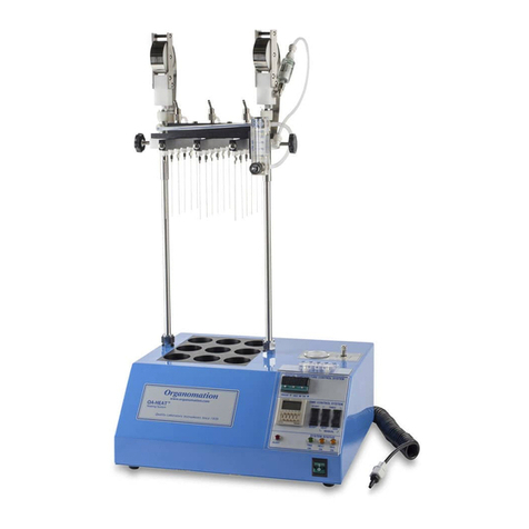
Organomation MICROVAP 11801 User manual

MICROVAP®
Nitrogen Evaporation System
Models
11801 (Single Plate)
11806 (6 Position)
11815 (15 Position)
11824 (24 Position)
INSTRUCTION MANUAL
266 RIVER ROAD WEST
BERLIN, MA 01503
U. S. A.
Tel: 888-838-7300 Fax: 978-838-2786
Email: sales@organomation.com


1
4
6
8
7
1
14
16
8
20
15
18
21
25
26
30
8
30
31
32
TABLE OF CONTENTSMICROVAP®
Introduction
Instrument Items Shipped ………………………….
Instrument Description …………………………….
Instrument Part Identification ……………………...
Safety Considerations - Read before operation …………
Installation
Location …………………………………………….
Bath Setup ………………………………………….
Instrument Setup …………………………………...
Operation
Instrument Control Identification …………………..
Planning and Preparation …………………………...
Bath Operation ……………………………………...
Instrument Operation ……………………………….
Maintenance and Cleaning ………………………………
Trouble Shooting …………………………………………
Technical Information …………………………………...
Parts List ……………………………………………
Service and Returns ………………………………...
Shipping - Claims for damage or shortage …………
Specifications ……………………………………….
Product designs are subject to change without notice
Printed in U. S. A.

V19.6 - 4 -
INTRODUCTIONMICROVAP®
Items Shipped
Carefully check the contents of all cartons received for damage which may have
occurred in transit. Retain all cartons and packaging materials until all components have been
checked against the packing slip, the component list below, and the equipment has been
assembled and tested. Contact Organomation immediately if any damage or discrepancies are
found.
Your shipment should contain one or more of the instruments shown below. Option codes are
listed on the next page.
Instrument Size
Single Plate N-EVAP Nitrogen evaporation system
6 Position N-EVAP Nitrogen evaporation system
15 Position N-EVAP Nitrogen evaporation system
24 Position N-EVAP Nitrogen evaporation system
Flowmeter Assembly with Mounting Bracket & Connector Tube
0-30 LPM for single plate MICROVAP
0-10 LPM for 15 position MICROVAP
0-20 LPM for 24 position MICROVAP
19ga x 2” Stainless Steel Needles, blunt end
8 dz for 1 Position MICROVAP (pre-installed)
19ga x 4” Stainless Steel Needles, blunt end
15 each for 15 Position MICROVAP
2 dz for 24 Position MICROVAP
OA-HEAT heater 180W, for single plate, and 6, 15, 24 position MICROVAP
ID #
11801
11806
11815
11824
NA1421
NA1221
NA1521
NA1807
NA0603
B1801
MICROVAP and OA-HEAT are Registered Trademarks of Organomation

V19.6 - 5 -
INTRODUCTIONMICROVAP®
Option Codes and additional items shipped
The following list contains option codes and items which may have been shipped in
conjunction with the standard parts shown on the previous page. Please check your packing
list and order information carefully to determine if these items are included in your shipment.
For a complete list of available accessories, please refer to the Accessories Section.
Your shipment may contain the following optional items:
Description
OA-HEAT heating unit has been modified for the Type-Z Purge
Intrinsically Safe bath option (passive operation). Additional parts
include: differential pressure gauge, mounting bracket, and tubing.
OA-HEAT heating unit is wired as a 240 Volt unit.
Option
-Z
-2

V19.6 - 6 -
INTRODUCTIONMICROVAP®
Instrument Description
The MICROVAP Nitrogen Evaporation System is designed for general evaporation
and / or concentration of analytical or biological samples in 96 well titer plates or sample tubes
under controlled and reproducible conditions. Other micro well plate configurations are
available.
Figure 1:
Single Block MICROVAP;
11801, 11806, 11815, 11824

V19.6 - 7 -
SAFETYMICROVAP®
Safety Considerations
READ THIS SECTION BEFORE EQUIPMENT OPERATION!
This equipment is designed for use in the Analytical or Environmental Laboratory by trained
laboratory personnel for evaporative applications. Use of this equipment beyond its stated
intended purpose and operating parameters is not recommended and will be the sole
responsibility of the user. This equipment should not be modified or altered. Organomation
assumes no liability for any misuse of or modification to this product and such misuse or
modification will immediately void all warranties.
This equipment should be used in accordance with the operating instructions contained in this
manual. For alternative uses not covered in this manual, please contact Organomation technical
department for product suitability, safety, and alternative operating instructions.
The following are general safety guidelines recommended when using this product. Please
consult your laboratory safety officer for any additional safety steps which may be necessary
for your specific application or material.
1. Thoroughly review your MSDS (Material Safety Data Sheets) for all chemicals to be
used with this equipment.
2. Do not use this equipment with materials with auto ignition points below 150 ºC.
3. Hand and eye protection are required when using this product. Additional protection
may be required with respect to the materials being used. Please consult your
laboratory safety officer.
4. This product should only be used in a chemical fume hood with adequate ventilation.
5. Do not move the product when hot - BURN HAZARD!
6. Do not open bath enclosure while energized - SHOCK HAZARD!
7. Repairs of electrical components should be conducted by a trained electrical technician.
Incorrect replacement parts or assembly may damage the product and create a serious
safety hazard for the user. Factory repair is recommended.
8. Highly flammable materials such as Petroleum Ether should not be used with this
product unless the Type-Z Purge intrinsically safe bath option is installed and operating.
9. Use of acidic or base materials may damage this product and is not recommended
unless the product was ordered with the optional corrosion resistant coating.

V19.6 - 8 -
INSTALLATIONMICROVAP®
Assembly Instructions: Single Plate; 6, 15 & 24 POSITION MICROVAP
Gather and identify all components.
A. Heating Unit
B. Stainless Steel Rod
C.Compression Spring
D.Instrument Manifold
E. Heat Block
F. Offset Collar
G. Manifold Thumb Screws
H. Accessory Thumb Screw
I. Hex Key [ 1/8” ]
J. Flowmeter Bracket
K. Flowmeter
L. Coiled Connector Tube Assembly

V19.6 - 9 -
INSTALLATIONMICROVAP®
Assembly Instructions: Single Plate; 6, 15 & 24 POSITION MICROVAP
Position heating unit [A]
on a flat surface.
Remove screws from rear top
surface.
Position flowmeter bracket [J] over
holes as shown.
Replace screws.
Remove screws from rear of
flowmeter [K]
Position flowmeter over bracket
holes as shown.
Replace screws.

V19.6 - 10 -
INSTALLATIONMICROVAP®
Assembly Instructions: Single Plate; 6, 15 & 24 POSITION MICROVAP
Use the 1/8” hex key [I] to loosen set
screw on rear block.
Insert the stainless steel rod [B] into
the block with the ball end facing up.
Center the alignment groove on the rod
to the back face of the rear mounting
block, facing away from the heating
unit.
Place the offset collar [F] over the rod
and lower until seated on the
mounting block.
Place the compression spring [C] over
the rod and lower until seated on the
offset collar.

V19.6 - 11 -
INSTALLATIONMICROVAP®
Assembly Instructions: Single Plate; 6, 15 & 24 POSITION MICROVAP
Screw the manifold thumb screws [G]
into the sides of the instrument
manifold [D].
Screw the accessory thumb screw [H]
into the upper back of the instrument
manifold.
*Do not over tighten. May damage the
threads or the rod when seating.
Tighten the set screw to secure rod in
place.
Place the instrument manifold over
the rod and lower until seated on the
offset collar.
*Adjustment may be required for
alignment pin in the back of the
instrument manifold.

V19.6 - 12 -
INSTALLATIONMICROVAP®
Assembly Instructions: Single Plate; 6, 15 & 24 POSITION MICROVAP
Attach the exposed end of the filter,
in the coiled connector tube assembly
[L], to the lower rear fitting of the
flowmeter.
Attach the other end of the connector
tube to a suitable gas source (10-30
PSIG).
Attach the manifold gas tube to the
upper fitting on the rear of the
flowmeter.

V19.6 - 13 -
INSTALLATIONMICROVAP®
Assembly Instructions: Single Plate; 6, 15 & 24 POSITION MICROVAP
Use the accessory thumb screw [H] for easier removal of the heat block.

V19.6 - 14 -
INSTALLATIONMICROVAP®
Location
The MICROVAP Evaporator System should be located on a bench top or in a chemical
fume hood if hazardous or flammable materials and solvents are to be used. The location
should provide the necessary support services for the instrument. These include electrical
power (required for heat unit) and a clean inert gas source (Air or Nitrogen). Please review the
Specifications Section for further information.
Heating unit Setup
1. Position the unit in a chemical fume hood.
2. Turn the main power switch to the “OFF” position.
3. Plug the bath electrical cord into a 3 wire grounded electrical outlet rated for 110-120
VAC, 50-60 Hz, single phase, 10 amps.
Optional 220 VAC baths are clearly marked and should be plugged into a 3 wire
grounded electrical outlet rated for 220-240 VAC, 50-60 Hz, single phase, 10 amps.
4. Pressure Reducing Regulator Option - If you do not have this option, proceed to
the next section.
When purchased with a MICROVAP System, this item is pre-installed onto the
flowmeter, between the flowmeter and the Connector Tube. To install a pressure
reducing regulator, please follow the instructions and figure below:
A. Remove the flowmeter from the bracket.
B. Remove the Connector Tube and fitting from the flowmeter.
C. Re-connect the flowmeter to the bracket.
D. Connect the Pressure Reducing Regulator to the lower fitting on the back of the
flowmeter. Position the regulator such that the adjustment knob is straight up
and the gauge points away from the bath.
E. Connect the Connector Tube to the regulator.
Flowmeter Regulator Assembly shown with Gas Connector Tube.

V19.6 - 15 -
OPERATIONMICROVAP®
Planning and Preparation
It is important to understand the procedures and equipment operation prior to the use of
the equipment. High speed nitrogen evaporation requires a balance of sample volume, nitrogen
flow, temperature, needle position and adjustment. Improper use can impair performance,
contaminate samples or result in loss of samples. Environmental conditions are also important,
examples include use of dry or wet heating media, hood airborne contaminates, gas purge
purity, and sample handling procedures. If you are unfamiliar with the use of the MICROVAP
System or are working with a new procedure, it is recommended that a trial run be made using a
sample blank to determine optimal operating conditions.
The MICROVAP System is designed to handle one to three 96 well plates simultaneously up to
the capacity of the equipment. 96 position deep well plates may also be used. Other well plates
of different capacities can also be accommodated, consult Organomation for details.
The MICROVAP System is manufactured utilizing inert materials. The white translucent and
black coiled tubing used is free of phthalate presence.

V19.6 - 16 -
OPERATIONMICROVAP®
Bath Controls Diagram
Turns power to the unit on and off
Adjusts the bath temperature
Indicates heating when heaters are energized,
will cycle at temperature
Heater power to samples
Picture ID Function
Main Power Switch
Digital Temperature Controller
Amber Light(s)
Black Rocker Switch
Description
A
B
C
D
Figure 3:
Layout for 11801, 11806, 11815, 11824
Front Back

V19.6 - 17 -
OPERATIONMICROVAP®
Bath Preparation
The single position MICROVAP is designed to accommodate sample arrays of 6, 15,
24, and 96 positions. Default program settings are dependent on the model purchased. It is
important to verify that your CAL3300 Digital Temperature Controller is properly tuned for
your application when switching between array configurations.
1. To access the program settings, press and hold both ▲ and ▼ simultaneously until the
screen reads
2. Release the arrow buttons, then navigate the menu using either the ▲ or ▼ keys
3. Hold ⁎ and press ▲ or ▼ to adjust settings
4. Once the appropriate settings for your application are confirmed, press and hold both ▲ and
▼ simultaneously to save your settings and complete your setup.
CAL 3300 Program Settings
11801
11806,
11815,
11824
Function Setting Setting
10 4.5
20 25
40 45
1.5 4
80 45
30 80
*Note: To navigate
between menu levels,
hold ⁎ and press ▲ or ▼
when the screen reads

V19.6 - 18 -
OPERATIONMICROVAP®
Bath Operation
Turn the main power
switch [A] on.
*The illuminated portion
should glow.
Digital Temperature Controller [B]:
Adjust the digital controller to the desired temperature set point.
To view the current set point:
hold the ⁎ key.
To change the current set point:
hold the ⁎ key and press either
the ▼ or ▲ keys.
*This setting will be retained
even after the system is turned
off.
To change the units of measure (°C or °F):
press and hold the ▼ and ▲ keys for 3
seconds.
Navigate to
hold ⁎ and press ▲ to adjust to level “2”
Navigate to
hold ⁎ and press ▼or ▲ to adjust to °C
or °F.
Press and hold ▼ and ▲ to save settings.

V19.6 - 19 -
OPERATIONMICROVAP®
Bath Operation
Press the black rocker switch [D] upwards to power the heaters on.
*Older models may not have idle switch option
Single Block MICROVAP

V19.6 - 20 -
OPERATIONMICROVAP®
Instrument Controls Diagram: Single Plate, 6, 15 & 24 POSITION MICROVAP
Locks manifold position when tightened
Open or close gas flow to distribution
manifold
Alters stopping height for manifold
Medium for heating samples
Controls flow rate of gas from supply
Picture ID Function
Thumb Knobs
Manifold Gas Valve
Offset Collar
Heat Block
Flow Meter Valve
Description
E
F
G
H
I
Figure 5: General MICROVAP Layout
This manual suits for next models
3
Table of contents
Other Organomation Laboratory Equipment manuals
Popular Laboratory Equipment manuals by other brands

Lubemaster
Lubemaster OS600 Standard Operating instructions and parts manual

Tuttnauer
Tuttnauer 1730 M Operation & maintenance manual

Labnet
Labnet Prism Mini user manual

Novita
Novita aircare pro NAS12000 OPERATING INSTRUCTIONS AND E-WARRANTY APPLICATION

Buchi
Buchi SyncorePlus Operation manual

Heidolph
Heidolph UNIMAX 1010 instruction manual

Rainin
Rainin Pipetman F Series manual

CORNING
CORNING Lambda EliteMax instruction manual

Sage Science
Sage Science PippinHT Operation manual

Manson Engineering Industrial
Manson Engineering Industrial DPD Series Operation manual

Goobay
Goobay 20319 user manual

Biolin Scientific
Biolin Scientific QSense quick start