MRC WBH-100 User manual

3, Hagavish st. Israel 58817 Tel: 972 3 5595252, Fax: 972 3 5594529
Circulation water baths
WBH-100/200
Operation manual
These units are circulation water baths for professional, industrial, or
educational use where the preparation or testing of materials is done at
approximately atmospheric pressure and no flammable, volatile or combustible
materials are being heated.
MRC LTD.
Hagavish 3 st.
HOLON 58817
ISRAEL
Tel (+972)-3-5595252
Fax (+972)-3-5594529
Website: www.mrclab.com

3, Hagavish st. Israel 58817 Tel: 972 3 5595252, Fax: 972 3 5594529
Section 1
INTRODUCTION
Thank you for choosing a circulation water bath. These units are not intended
for use at hazardous or household locations. Before you use the unit, read this
entire manual carefully to understand how to install, operate, and maintain the
unit in a safe manner. Your satisfaction with the unit will be maximized as you
read about its safety and operational features.
Keep this manual on-hand so it can be used by all operators of the unit. Be sure
all operators of the unit are given appropriate training before you put the unit in
service.
Note: Use the unit only in the way described in this manual. Failure to follow the
guidelines and instructions in this manual may be dangerous and illegal.
General Safety Considerations
Your water bath and its recommended accessories have been designed and
tested to meet strict safety requirements.
For continued safe operation of your water bath, always follow basic safety
precautions including:
•Read this entire manual before using the water bath.
•Be sure you follow any city, county, or other ordinances in your area
regarding the use of this unit.
•Use only approved accessories. Do not modify system components. Any
alterations or modifications to your water bath may be dangerous and will
void your warranty.
•Always plug the unit’s power cord into a grounded electrical outlet that
conforms to national and local electrical codes. If the unit is not grounded,
parts such as knobs and controls may conduct electricity and cause
serious injury.
•Do not connect the unit to a power source of any other voltage or
frequency beyond the range stated on the power rating overlay at the
rear of the unit.
•Do not modify the power cord provided with the unit. If the plug does not
fit an outlet, have a proper outlet installed by a qualified electrician.
•Avoid damaging the power cord. Do not bend it excessively, step on it,
place heavy objects on it. A damaged cord can easily become a shock or
fire hazard. Never use a power cord after it has become damaged.
•Do not position equipment in a manner that prohibits access to power
cord.
•Do not attempt to move the unit during operation or before the unit has
been allowed to cool.

3, Hagavish st. Israel 58817 Tel: 972 3 5595252, Fax: 972 3 5594529
Section 2
RECEIVING YOUR UNIT
Before leaving our factory, all units are packaged in high quality shipping
materials designed to provide protection from transportation related damage.
Once a unit leaves our factory, however, safe delivery becomes the
responsibility of the carrier who is liable for loss or damage to your unit. Damage
sustained during transit is not covered under your unit warranty.
When you receive your unit, inspect it for concealed loss or damage to its
interior and exterior. Should you find any damage to the unit, follow the carrier’s
procedure for claiming damage or loss.
Inspection Guidelines
Carefully inspect the shipping carton for damage. If the carton is damaged,
report the damage to the carrier service that delivered the unit.
If the carton is not damaged, open the carton and remove its contents.
Carefully check all packaging before discarding. Save the shipping carton until
you are sure everything is in order.
Returning Shipment
If you must return the unit for any reason, first contact your service
representative for authorization. You will be asked to provide the data plate
information. See Recording Data Plate Information.
Recording Data Plate Information
Once you have determined the unit is free from damage, locate the data label at
the back of the unit. The data label indicates your unit’s model number and
serial number.

3, Hagavish st. Israel 58817 Tel: 972 3 5595252, Fax: 972 3 5594529
Section 3
INSTALLATION
Your satisfaction and safety require a complete understanding of this unit. Read
the instructions thoroughly and be sure all operators are given adequate training
before attempting to put the unit in service.
This equipment must be used only for its intended application; any alterations or
modifications will void your warranty. Local city, county, or other ordinances may
govern the use of this equipment. If you have any questions about local
requirements, please contact the appropriate local agency. The end user may
perform installation.
Customer service should be contacted for operating conditions outside these
limits.
Environmental Conditions
Under normal circumstances these units are intended for use indoors, at room
temperatures between 18ºC and 40ºC, at no greater than 80% relative Humidity
(at 25ºC) and with a supply voltage that does not vary by more than
10% from the data plate rating. This equipment should not be operated at an
altitude exceeding 2000 meters.
Power Source
Check the data label for voltage, cycle, and ampere requirements. If matched to
your power source, plug the power cord into a grounded outlet.
Voltage should not vary more than ± 10% from the data label rating.
These units are intended for 50/60-HZ application. A separate circuit is
recommended to prevent damage to the unit due to overloading or circuit failure.
Location
In selecting a location, consider all conditions that might affect performance,
such as heat from radiators, ovens, autoclaves, etc. Avoid direct sun, fast-
moving air currents, heating and cooling ducts, and high traffic areas. Allow a
minimum of 10 cm between the unit and any walls or partitions that might
obstruct free airflow.

3, Hagavish st. Israel 58817 Tel: 972 3 5595252, Fax: 972 3 5594529
Lifting and Handling
These units can be heavy for some people and care should be taken to use
appropriate lifting devices that are sufficiently rated for these loads. Units should
only be lifted from their bottom surfaces. Handles and knobs are not adequate
for lifting or stabilization. The unit should be completely restrained from tipping
during lifting or transport.
All moving parts such as trays or covers should be removed during transfer to
prevent shifting and damage.
Cleaning and Decontamination
In the event hazardous material is spilled onto or into the equipment appropriate
decontamination must be carried out. If there is any doubt about the
compatibility of decontamination or cleaning agents with parts of the equipment
or with material contained, please contact the manufacturer.
Units are cleaned at the factory, but not sterilized. Remove any racks if
assembled and clean the bath with a disinfectant that is suitable for your
application. See Maintenance Section for cleaning instructions and
precautions.

3, Hagavish st. Israel 58817 Tel: 972 3 5595252, Fax: 972 3 5594529
Section 4
CONTROLS AND COMPONENTS
OVERVIEW
Power Switch
The Red (On/Off) power switch, located in the top right-hand corner of the
control panel, controls all power to the unit. It must be in the I position to be ON
and illuminated before any systems are operational. The on/off switch must
remain easily accessible at all times.
Bath Cover
Using the bath cover supplied with your accessories will accelerate heat-up time
and reduce evaporation.
The cover must be used to reach set points above 60ºC. The bath cover is not
designed to be airtight and create a pressurized environment.
Internal bath components

3, Hagavish st. Israel 58817 Tel: 972 3 5595252, Fax: 972 3 5594529
Main Temperature Controller
Number
Key
Description / Function
③
For setting and calling up parameters.
④
To increase the value of digits.
⑤
To decrease the value of digits.
⑥
R
Revert /STOP/Restart Timer (For machine with timer use
only)
⑦
PV
To display process value, menu symbol and error code.
⑧
SV
To display set point value, parameter value or control
output value.
⑨
C
Process Unit Indicator- Celsius
⑩
ALM 123
Indicator
Over-Heat Temperature.
Lights on when actual temperature over the set
temperature 5℃, and turns off the heater.
⑪
OUT 1 2
Control output lamp 1.
Light on when heater is activated
⑫
MANU
Lamp flashes during Manual Mode operates
⑬
COMM
Communication indicator
⑭
TUNE
Lamp flashes during auto-tuning operates
⑮
Lock indicator
Setting parameter
The PV display indicates the parameter symbol, and the SV display indicates
the selected value of the selected parameter.

3, Hagavish st. Israel 58817 Tel: 972 3 5595252, Fax: 972 3 5594529
Section 5
OPERATION
Warning: These baths are not intended for use as acid baths. Use as an acid
bath will cause severe damage to bath components and void your warranty. Do
not use deionized water, tap water, or chemicals. USE DISTILLED WATER
ONLY.
Turning On the Unit
To turn on the unit, perform the following steps:
1. Check power supply against unit serial plate; they must match.
2. Plug service cord into the electrical outlet. If supplied with a detachable
cordset, plug the female end into the unit inlet and the male plug into the power
supply. 3. Fill bath to your required depth with DISTILLED WATER.
DO NOT USE TAP WATER, DEIONIZED WATER, OR CHEMICALS. Normal
depth is 5 ½ inches (14 cm), but depth must be at least 4.7 inches (12 cm) over
the bottom of the rack. Check water level frequently, add water to appropriate
levels if needed. At higher operating temperatures, or under circumstances
where a cover cannot be used, it will be necessary to check the water level
more frequently.
4. Push the Main power switch to the ON position.
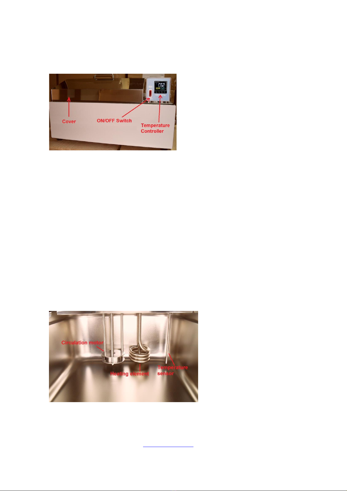
Bath Cover
Using the bath cover supplied with your accessories will accelerate heat-up time
and reduce evaporation.
The cover must be used to reach set points above 60ºC. The bath cover is not
designed to be airtight and create a pressurized environment.
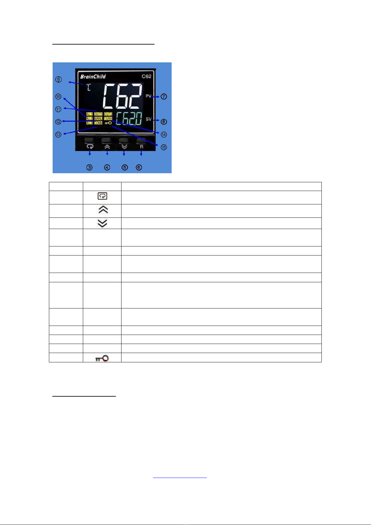
Setting Main Temperature Control
Turn on the temperature controller/power switch. The temperature displays light
up and after a few seconds, the upper display shows the present value (PV)
temperature. The lower display shows the set value (SV) or set temperature.
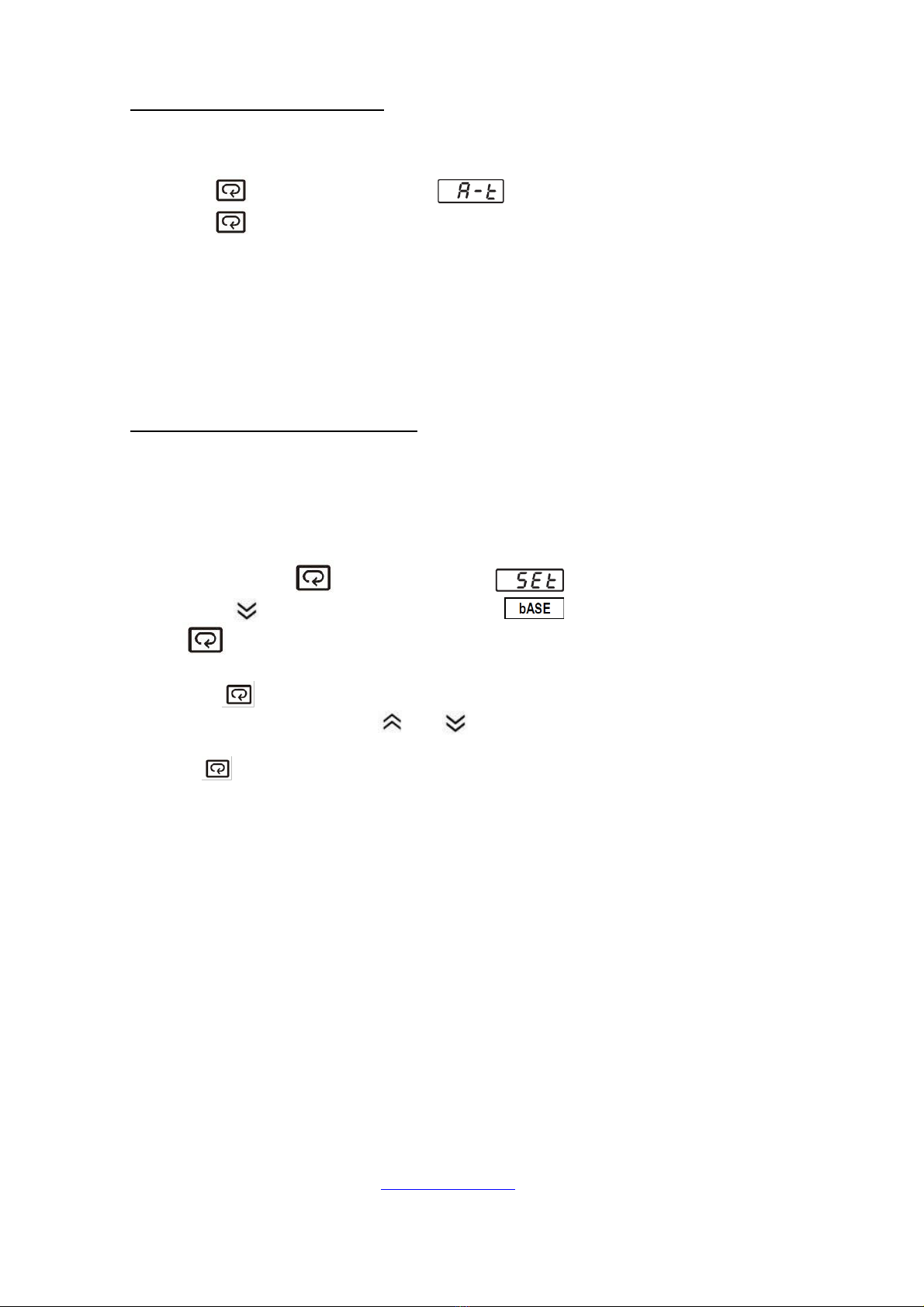
To enter set point mode on the control, push and release either the UP or
DOWN arrow pad one time and the digital display will start to blink.
Press to increase temperature gradually.
Press to decrease temperature gradually.
While blinking, the digital display shows the set point that can be changed.
Allow at least two (2) hours for the temperature to stabilize.
Warning: If the tank boils dry while containing plastic ware, the plastic will melt.
If you intend to use test tube racks, remember that plastic coated wire racks
may wear and expose metal that can cause damage. Preferably, use all plastic
racks.
Note: The heating element of this bath does not contact the tank bottom and
burn out if the tank is allowed to run dry.
Never turn on the unit if the tank is empty from water or if the water level is
too low

3, Hagavish st. Israel 58817 Tel: 972 3 5595252, Fax: 972 3 5594529
Auto-Tuning (only if needed)
Instrument has been set the best PID value; we suggest executing auto-
calculating when temperature is unstable. Enter auto-calculating:
Press and hold until appears on the display then release.
Press and hold at least 5 seconds. The TUNE indicator will begin to
flash and the auto-tuning procedure is beginning.
After the Auto-Tuning process is completed, the TUNE indicator will stop
flashing and the unit will revert to PID control by using its new PID values.
The PID values obtained are stored in nonvolatile memory.
Note: To enable auto-tuning the lock parameter should be set to 1000
User Calibration (only if needed)
Each unit is calibrated in the factory before shipment. The user can still modify
the calibration in the field.
There are two parameters: Offset Low (OFTL) and Offset High (OFTH) for
adjustment to correct an error in the process value.
Press and hold the key until the setup Menu page is obtained.
Then, press key to scroll to the parameter .
Press key several times to scroll to the parameter OFTL to calibration low
value. Send your low signal to the sensor input of the controller, then press and
release the key. If the process value (the upper display) is different from the
input signal, the user can use and to change the OFTL value (the lower
display) until the process value is equal to the value the user needs. Press and
hold the key for 5 seconds to complete the low point calibration. A similar
procedure is applied for high scale calibration.
The two points OFTL and OFTH construct a straight line. For the
purpose of accuracy, it is best to change the value same on the two points as
possible.

3, Hagavish st. Israel 58817 Tel: 972 3 5595252, Fax: 972 3 5594529
Section 6
MAINTENANCE
Warning: Prior to any maintenance or service on this unit, disconnect the power
cord from the power supply and empty the water from the tank. Before
reattaching the unit to its power supply, be sure all volatile and flammable
cleaners are evaporated and dry.
Draining Tank
1. Position the left side of the water bath over a sink or appropriate receptacle
large enough to hold the quantity of water to be drained (10 liters for the WBH-
100 and 20 liters for the WBH-200)
Cleaning
1. Clean the water bath with mild soap and water solution. DO NOT USE
chlorine-based bleaches, as they will damage the tank interior. DO NOT USE
spray cleaners that may contain solvents, which could leak through openings
and cracks and harm electrical part coatings. Failure to do this may permanently
damage the unit.
2. Rinse the water bath with clean water and wipe dry with a soft cloth. Stainless
steel does not rust, but foreign materials in the tank may rust or leave rust spots.
If corrosion is seen, scrub out the stains with a mild abrasive, never steel wool.
Storage
If the unit is to be shut down for an extended period of time, the tank must be
emptied and cleaned as described above. No adjustments to controls should be
necessary when the unit is put back in service.
If you are shutting the unit down for transport, perform the following steps:
1. Turn the unit off.
2. Disconnect from the power supply.
3. Remove the bath cover.
4. Empty and clean the tank.
5. Please see Lifting and Handling for further instruction.
6. No maintenance is required on any of the electrical components.
This manual suits for next models
1
Table of contents
Other MRC Laboratory Equipment manuals
Popular Laboratory Equipment manuals by other brands

logos biosystems
logos biosystems CELENA X user manual

Evertree
Evertree Liva EBS Series user manual

EMP-Centauri
EMP-Centauri P.123-A instruction manual

ThermoFisher Scientific
ThermoFisher Scientific invitrogen iSort Series manual

Agilent Technologies
Agilent Technologies 7200 Operation manual

caron
caron 2050 Operation manual