Ladybug LB5900 Series User manual

DOC: Recorder Out Operation –V2.0 April 2016
LB5900 Series Sensor Recorder Output Operation Guide
The Recorder Output function (Option 001) is a 0 to 1 VDC settable output that is proportional to the
measured RF input power. Note that on LB5900 series sensors Wideband Detector Out and Trigger Out
share the connector with Recorder Out. Only one can be used at any one time. PMA-12 sets the output
to Recorder Out automatically when Recorder Out is selected using the Mode dropdown menu. Once
this is done, the Start RO button can be used to enable and disable Recorder Out. The recorder output
signal passes through a 40 Hz hardware filter and the output is updated 1000 times per second.
An important unique feature of LadyBug’s Recorder Output Option is that it is capable of running when
no computer is connected if Option UOP (Unattended Operation) is also installed. For example, after the
options are set up, and Recorder Out is active, the sensor can be powered through the USB cable or
through the SPI cable if Option SPI has been purchased; and recorder output will deliver a calibrated
analog output if set accordingly. Review the Recorder Out in Unattended Operation section for
additional information.
Figure 1 - Recorder Out Setup
The level setup for the Recorder Out is located in the Sensor’s Detail
Tab. Setup is accomplished by establishing a desired power level for
0-Volts (lower power level) on the Recorder Output and a power
level that is to result in a 1-Volt Output (the higher power level).
Power applied below the lower level will result in a 0-Volt output;
and power over the higher power will result in a 1-Volt output. It is
important to remember that the sensor’s output MUST be driven
into a 1,000 ohm load (see image at right). The output voltage will
not be correct without the load. Once the settings are established,
the output will be a linear representation of the power between the two levels. The output voltage
inside these ranges is a calibrated DC measurement value.

DOC: Recorder Out Operation –V2.0 April 2016
To set up Recorder Out, identify the minimum and maximum power levels (in dBm) that you require.
Place these values in the RecorderOutLowerLimit and RecorderOutUpperLimit in the left hand pane as
shown in Figure 1. Once the values are established, the formula below can be used to determine the
output voltage (Vout) for any given dBm power level.
Vout= (10^(PMEAS/10)-10^(ZeroVoltSet/10))/(10^(OneVoltSet/10)-10^(ZeroVoltSet/10))
The same formula (shown below) can be copied and pasted into excel at cell B4. When pasted into cell
B4, the cells listed below will establish the inputs values. All power units are in dBm. Out of range data is
not accounted for.
B1 is the dBm power setting to deliver for 1 Volt
B2 is the dBm power setting to deliver 0 Volts
B3 is the actual input power.
=(10^(B3/10)-10^(B2/10))/(10^(B1/10)-10^(B2/10))
Grounding Note
LB5900 Sensors have solid grounding between the USB shield, USB Common and SMB (Recorder Out)
Common connections. It is important to take ground current into consideration between all connected
equipment. LadyBug Recorder Out resolution specifications are generally (see specification sheet for
exact specification and sensor accuracy data) in the range of 25 micro volts. Small ground currents
caused by power across shielded cables can swamp the measured output voltage if care is not utilized.
For example, many USB cables exhibit shield and common resistance of greater than an ohm. In this
case, with 200 ma current draw from the sensor, there will be 200mv across the sensor USB cable. If the
computer and the device monitoring the Recorder signal share common grounding, this current will be
driven in a loop and may result in a ground offset voltage on the monitoring device as depicted by the “I
loop” shown in Figure 2. This offset voltage may dynamically change as the sensor’s current draw
changes and along with other changes in the ground system.
Figure 2 - Ground Management

DOC: Recorder Out Operation –V2.0 April 2016
Using Recorder Out in Unattended Mode
If both Option UOP (Unattended Operation) and Option 001 (Recorder Output) have been installed, a calibrated 0
to1 volt analog output can be obtained from the sensor while operating in Unattended Mode. Care must be utilized
if the output is used to control other equipment.
During the power up cycle when UOP is active, Recorder Output will exhibit voltage transitions from 0 volts to 5
volts until the sensor’s processor is running. After stability; and prior to measurement, the output will be at 1 volt
(into its specified 1000 ohm load); after the sensor begins normal operation, the output will be stable and is updated
1000 times per second. Depending on the sensor model, firmware version and the number stored measurements,
time to stability can be up to 20 seconds.
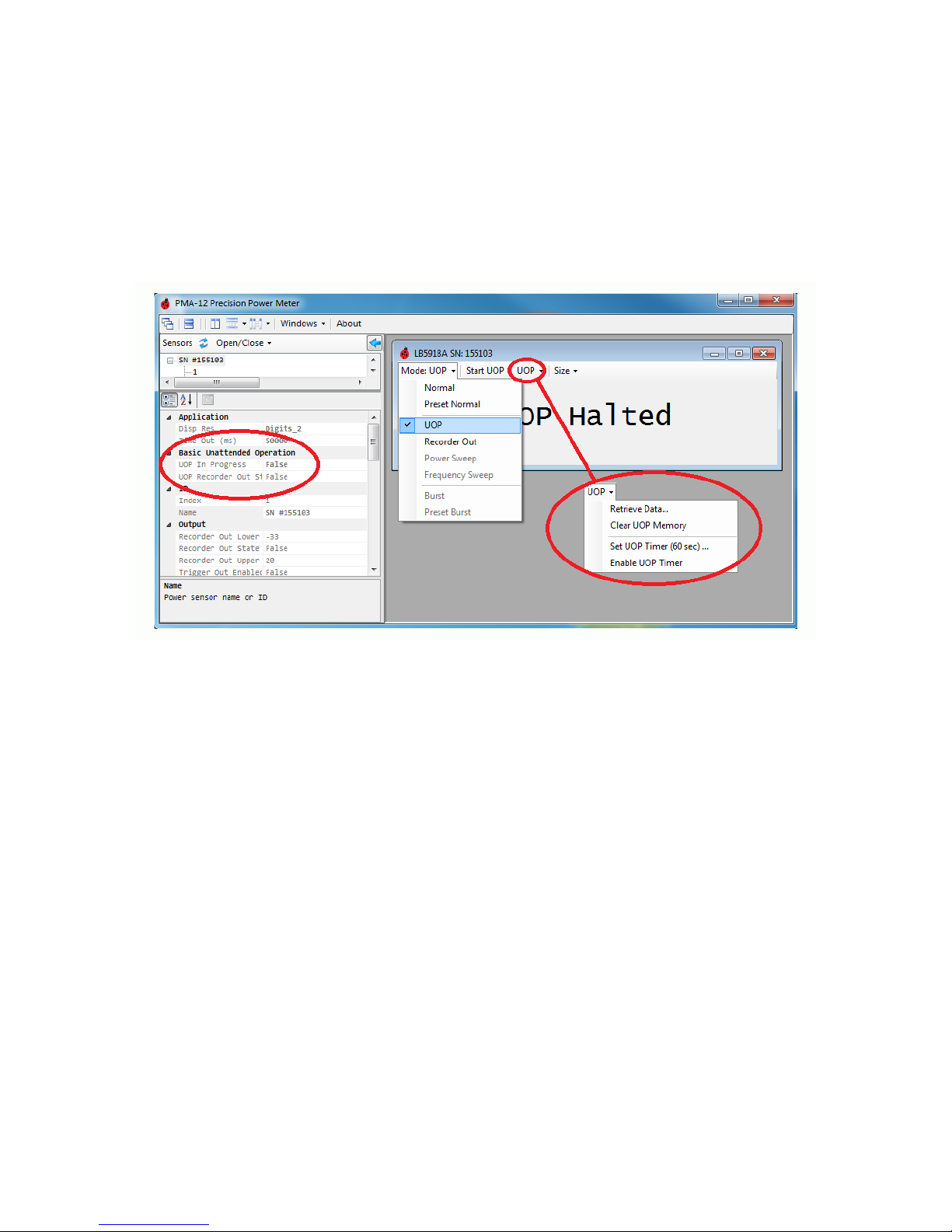
Figure 3 - Recorder Out in Unattended Operation
To protect equipment that may be controlled by Recorder Out, the default condition for Recorder Out when
returning from power up is always OFF unless specifically set otherwise, this includes power up in Unattended
Operation. To enable Recorder Out for use while the sensor is operating in Unattended Operation mode, a special
function must be set. This parameter, UOP Recorder Out State, is circled at left in Figure 3. When set to True,
Recorder Out will function while the sensor is running in Unattended Mode. The parameter can only be changed
when the sensor is operating in Normal Mode (Figure 3 middle, Mode). While the sensor is in UOP Active (In
progress) the function will remain set and the sensor can be repeatedly power cycled without losing the Recorder
Out during UOP state. If the sensor is powered up while UOP is not active, UOP Recorder Out State will be cleared
to FALSE and Recorder Out will not operate in Unattended Operation unless the parameter is set again.
Unattended Recorder Out Example
To enable Recorder Out while in Unattended Operation, perform the following.
1. Set the sensor to Preset Normal and set your Frequency
2. Set Recorder Out Upper and Lower Limits (See Recorder Out section for info)
3. In the Sensor Window, Under the Mode Dropdown, Set the mode to Recorder Out (Figure 3 middle)
4. Verify Recorder Out functionality
5. Under the Mode Dropdown, Set the mode back to Normal (Figure 3 middle)
6. Under Basic Unattended Operation, set UOP Recorder Out State to True (Figure 3 left)
7. In the Sensor Window, Under the Mode Dropdown, Set the mode to UOP (Figure 3 middle)
8. In the Sensor Window, Click Start UOP
9. Recorder Out becomes active
10. Remove and Reconnect power several times to verify
11. Connect to the computer, select Halt UOP, set Mode to Normal set UOP Recorder Out State to False
Other manuals for LB5900 Series
2
Table of contents
Other Ladybug Accessories manuals