10
a) Szyba przednia jest zabrudzona lub uszkodzona (wyczyścić lub filtra samościemniającego, a następnie wyjąć szybkę w kierunku
wnętrza przyłbicy.
wymienić).
UWAGA! Wymiany i instalacji wkładu filtrującego, powinien dokonywać
b) Czujniki są zabrudzone (wyczyścić powierzchnię czujników).
wykwalifikowany i przeszkolony personel.
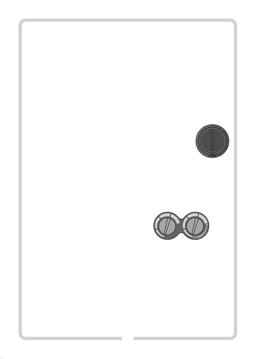
c) Prąd spawania jest zbyt niski (przestawić przełącznik czułości do
położenia "HI").nWymiana baterii zasilających filtr
Jeśli zaświeci się wskaźnik diodowy oznaczony „LOW BAT” należy wymieć
d) Baterie zasilające wyczerpały się (wymienić baterie).
baterie na nowe.
3. Wolna reakcja Baterie umieszczone są w dwóch niezależnych komorach na kasecie
a) Temperatura robocza jest zbyt niska (nie używać przyłbicy w filtra. W celu wymiany baterii należy obrócić i zdjąć pokrywę komory.
temperaturze poniżej -5°C). Zużytą baterię wyjąć z komory i zastąpić ją nową.
4. Słaba widoczność Zamknąć pokrywę i powtórzyć opisaną powyżej operację z drugą
a) Szyba przednia / wewnętrzna i/lub filtr są zabrudzone (wyczyścić baterią.
lub wymienić ). UWAGA! Baterie wymieniać tylko parami. Nie mieszać baterii zużytej z
b) Oświetlenie otoczenia jest niewystarczające (oświetlić nową.
prawidłowo).
c) Nieprawidłowo ustawiony stopień zaciemnienia filtra (sprawdzić
zalecane stopnie zaciemnienia podane w tej instrukcji i ustawić
prawidłowy).
5. Przyłbica zsuwa się z głowy
a) Opaska na głowę nie jest wyregulowana prawidłowo
(wyregulować opaskę).
10. KONSERWACJA I PRZECHOWYWANIE:
Należy regularnie i starannie dokonywać prac konserwacyjnych
przyłbicy. Pozwoli to na zachowanie maski w dobrym stanie
technicznym.
Wyrób należy przechowywać w dostarczonych opakowaniach
jednostkowych w ciemnym, suchym, przewiewnym i zamkniętym
pomieszczeniu. Podczas przechowywania, nie przekraczać zakresu
temperatur od -20 st. C. do +70 st. C. Chronić przed kurzem, pyłem i
innymi zanieczyszczeniami (worki foliowe, torebki itp.) Chronić przed
uszkodzeniami mechanicznymi. Transport - w dostarczanych
opakowaniach jednostkowych, w kartonach, w zamkniętych środkach
transportu.
nCzyszczenie
Filtr czyścić można przy pomocy czystej i gładkiej szmatki lub materiału
bawełnianego.
Nie zanurzać przyłbicy i filtra w wodzie i nigdy nie używać środków
ścierających, rozpuszczalników i detergentów na bazie oleju.
Nie otwierać kasety filtra samodzielnie. Kaseta filtra może zostać
rozmontowana przez autoryzowany serwis lub wykwalifikowaną osobę.
W innym wypadku dojdzie do utraty gwarancji.
nWymiana szybki ochronnej:
W celu zapewnienia wieloletniej bezawaryjnej pracy filtra zabronione
jest używanie przyłbicy pozbawionej poliwęglanowych szybek
ochronnych. Należy regularnie wymieniać frontową szybkę ochronną,
ktora ulega naturalnemu zmatowieniu w wyniku uderzania o nią
odprysków podczas spawania.
W celu wymiany szybki ochronnej należy najpierw wymontować kasetę
OCHRONA ŚRODOWISKA:
UWAGA! Przedstawiony symbol oznacza zakaz umieszczania
zużytego sprzętu łącznie z innymi odpadami (z zagrożeniem
kary grzywny). Składniki niebezpieczne znajdujące się w
sprzęcie elektrycznym i elektronicznym wpływają
negatywnie na środowisko naturalne i zdrowie ludzi.
Gospodarstwo domowe powinno przyczyniać się do odzysku i
ponownego użycia (recyklingu) zużytego sprzętu. W Polsce i w Europie
tworzony jest, lub już istnieje, system zbierania zużytego sprzętu, w
ramach którego wszystkie punkty sprzedaży ww. sprzętu mają
obowiązek przyjmować zużyty sprzęt. Ponadto istnieją punkty zbiórki
ww. sprzętu.
11. OBJAŚNIENIE OZNACZEŃ FILTRA:
MODEL: ADF GX-800S – model filtra samościemniającego;
CAN/CSA Z94.3 – kanadyjska norma bezpieczeństwa;
ANSI Z87.1 – amerykańska norma bezpieczeństwa;
4/9-13 GX 1/1/1/2/379 CE – oznakowanie filtra spawalniczego z
ręcznym ustawianiem stopnia ochrony, gdzie:
4 - nr stanu jasnego; 9 - nr najjaśniejszego stanu ciemnego; 13 - nr stanu
najciemniejszego; GX – kod producenta,
1 - klasa optyczna; 1 - klasa rozproszenia światła; 1 - klasa odchylenia
współczynnika przepuszczania światła; 2 - klasa zależności
współczynnika przepuszczania światła od kąta; 379 - nr normy
europejskiej dotyczącej automatycznych filtrów spawalniczych EN 379,
CE - znak zgodności z dyrektywami nowego podejścia WE.
GX EN 175 F CE – oznakowanie przyłbicy, gdzie: GX – kod producenta,
EN 175 – europejska norma bezpieczeństwa; F – symbol odporności na
uderzenie o niskiej energii; CE - znak zgodności z dyrektywami nowego
podejścia WE.
IMPORTER/UPOWAŻNIONY PRZEDSTAWICIEL:
Profix Sp. z o.o.,
ul. Marywilska 34,
03-228 Warszawa, Polska
Polityka firmy PROFIX jest polityką stałego udoskonalania swoich produktów i dlatego firma rezerwuje sobie prawo zmiany
specyfikacji wyrobu bez uprzedniego zawiadamiania. Obrazki, podane w instrukcji obsługi, są przykładowe i mogą się
nieznacznie różnić od rzeczywistego wyglądu zakupionego urządzenia.
Niniejsza instrukcja jest chroniona prawem autorskim. Kopiowanie/ powielanie jej bez pisemnej zgody firmy Profix Sp. z o.o.
jest zabronione.