1. Usable 5’’ (125
mm) angle grinder’s rated power must be at least
limit is up to 12 000 min-1
(RPM), grinder spindle thread must be
which is common angle
grinder spindle thread in European and other metric system countries
recommended that the grinder be equipped with soft start system and electrical or mechanical
safety clutch.
2. The log peeling and shaping
spindle using its internal reinforced thread
flange
(figure 2, pos. 2) is in use and its
the tool’s fixing thread 5/8”-
32x2 mm (figure 1, pos. 4)
pos. 3). The
seal prevents to avoid tool loosening after angle grinder motor is turnef off.
brake and therefore it is
3. Tool thread connection 5/8”-
flange with a special angle
important to use gloves, because there is a risk to injure operator’s hand against the cutting blades
when the wrench
4. Always disconnect the
1, pos,
2) or when performing any general maintenance activities (such as adjusting or cleaning).
Remove dust, wood resin
5.
Handle cutting blades with care. After sharpening, the blades can
use gloves! Sharpening
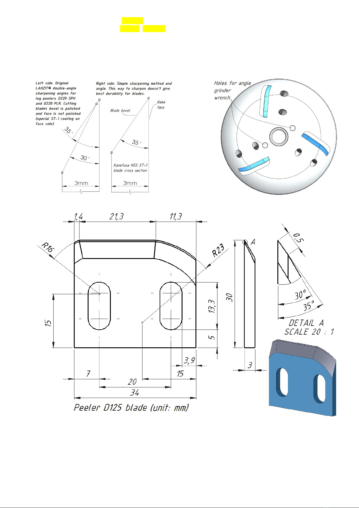
geometry and other related
6. Cutting blades m
ust be adjusted according to peeling process
requires to adjust larger
of blades to 0.5…1.0mm.
Make sure that the cutting blades are equally adjusted (figure 3).
Fig 1.
Complete log peeling and shaping
tool D125 PLR shown with it’
Fig 3.
Principle of peeling and shaping tool D125
must be on the same level. You can check it for example using small plywood piece
leave
3 notches to the same level on the plywood!
mm) angle grinder’s rated power must be at least
(RPM), grinder spindle thread must be
5/8”-
11 (most common in the USA)
grinder spindle thread in European and other metric system countries
recommended that the grinder be equipped with soft start system and electrical or mechanical
tool D125 PLR (figure 1, pos. 1) will be a
spindle using its internal reinforced thread
5/8”-11 (figure 1, pos. 5).
(figure 2, pos. 2) is in use and its
step edge
with diameter 22.23 mm / 7/8’’
like it is shown on the figure 2.
Make sure the rubber seal
before fixing the tool to the grinder’s spindle (figure 2,
always includes spare seal OR 32x
2 mm, rubber mark NBR 70. This
seal prevents to avoid tool loosening after angle grinder motor is turnef off.
this O-ring condition.
must be tightened
until there is no cap between tool body and disc
using special holes for that in tool body (figure 5). I
important to use gloves, because there is a risk to injure operator’s hand against the cutting blades
slip away. Please be very
from the power source when changing
2) or when performing any general maintenance activities (such as adjusting or cleaning).
using a special brass
cleaning tool which includes
Handle cutting blades with care. After sharpening, the blades can
geometry and other related
information is shown in figure 4
ust be adjusted according to peeling process
(up to 2.0
mm), the wood surface finishing needs adjustment
Make sure that the cutting blades are equally adjusted (figure 3).
Complete log peeling and shaping
Fig 2. Attatching shem
shaping
tool D125 PLR to the 5’’ (125 mm) angle
grinder.
Principle of peeling and shaping tool D125
PLR cutting blades adjusting
must be on the same level. You can check it for example using small plywood piece
3 notches to the same level on the plywood!
max spindle speed
11 (most common in the USA)
,
grinder spindle thread in European and other metric system countries
. It is
recommended that the grinder be equipped with soft start system and electrical or mechanical
to the angle grinder
grinders disc
with diameter 22.23 mm / 7/8’’
is directed towards
Make sure the rubber seal
(O-ring) OR
before fixing the tool to the grinder’s spindle (figure 2,
2 mm, rubber mark NBR 70. This
seal prevents to avoid tool loosening after angle grinder motor is turnef off.
It works as a frictional
until there is no cap between tool body and disc
using special holes for that in tool body (figure 5). I
t is
important to use gloves, because there is a risk to injure operator’s hand against the cutting blades
,
from the power source when changing
cutting blades (figure
2) or when performing any general maintenance activities (such as adjusting or cleaning).
cleaning tool which includes
with the tool kit.
– therefore always
information is shown in figure 4
and figure 6.
- the thicker bark of log
mm), the wood surface finishing needs adjustment
Make sure that the cutting blades are equally adjusted (figure 3).
tool D125 PLR to the 5’’ (125 mm) angle
PLR cutting blades adjusting
– blades cutting edges
must be on the same level. You can check it for example using small plywood piece
- cutting edges must