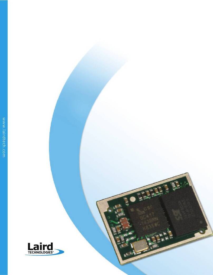
Laird LSR STERLING-LWB STM User manual

The information in this document is subject to change without notice.
330-0234-R1.2 Copyright ©2016-2017 LSR
STERLING-LWBTM STM EXPANSION BOARD
USER GUIDE
Last updated
February 9, 2017

Sterling-LWB STM Expansion Board
USER GUIDE
The information in this document is subject to change without notice.
330-0234-R1.2 Copyright ©2016-2017 LSR Page 1of 25
Table of Contents
1. Introduction ..........................................................................................................................................3
1.1 Purpose & Scope ..........................................................................................................................................3
1.2 Applicable Documents .................................................................................................................................3
1.3 Revision History............................................................................................................................................3
1.4 Related LSR Products ...................................................................................................................................3
2. Sterling-LWB STM Expansion Board Description ..................................................................................4
2.1 Sterling-LWB STM Expansion Board Hardware............................................................................................4
2.2 Sterling-LWB Wi-Fi + Bluetooth Combo Module..........................................................................................5
2.3 USB JTAG and Serial Interface......................................................................................................................5
2.4 SPI Flash .......................................................................................................................................................6
2.5 User I/O........................................................................................................................................................6
2.6 Micro-SD Slot ...............................................................................................................................................6
2.7 Bluetooth Audio Header ..............................................................................................................................6
3. Software Development with the Sterling-LWB STM Expansion Board.................................................7
3.1 Required Equipment ....................................................................................................................................7
3.2 Required Software .......................................................................................................................................8
3.2.1 Cypress WICED Studio and WICED SDK.................................................................................8
3.2.2 Downloading the Cypress WICED SDK .................................................................................. 9
3.2.3 Installing the Cypress WICED Studio and WICED SDK.........................................................10
3.2.4 Adding the Sterling-LWB Platform to your WICED Installation ..........................................10
3.2.5 Using the Cypress WICED Studio.........................................................................................10
3.2.6 Understanding the WICED SDK Folder Structure................................................................11
3.3 WICED Software Examples.........................................................................................................................12
3.3.1 Finding demo and code snippets ........................................................................................12
3.3.2 Snippets for learning the WICED framework......................................................................12
3.3.3 Snippets for Wi-Fi................................................................................................................12
3.3.4 Snippets for Bluetooth ........................................................................................................12
3.4 Editing and Building Applications using WICED Studio ..............................................................................13
3.4.1 Application Makefiles and Source Files ..............................................................................13
3.4.2 Building an Application .......................................................................................................13
3.5 Downloading an Application to your Sterling-LWB STM Expansion Board................................................14
3.5.1 Installing the WICED JTAG Adapter Driver..........................................................................14
3.5.2 Performing a “Build and Download” from WICED Studio...................................................15
3.5.3 Downloading WLAN firmware as part of the “Build and Download” step .........................15
4. Troubleshooting..................................................................................................................................16
4.1 Understanding the Role of OpenOCD ........................................................................................................16
4.2 OpenOCD Log.............................................................................................................................................16

Sterling-LWB STM Expansion Board
USER GUIDE
The information in this document is subject to change without notice.
330-0234-R1.2 Copyright ©2016-2017 LSR Page 2of 25
5. Sterling-LWB Cloud Sensor Demo featuring TiWiConnect .................................................................17
5.1 Downloading the Sensor Demo Source Code ............................................................................................17
5.2 Building and Downloading the Sensor Demo.............................................................................................18
5.3 Monitoring the Debug Output of the Sensor Demo ..................................................................................18
5.4 ModuleLink Sterling Mobile App................................................................................................................19
5.4.1 Creating a TiWiConnect Account ........................................................................................19
5.4.2 Device List View ..................................................................................................................19
5.4.3 Configuring your Sterling-LWB for Wi-Fi.............................................................................19
5.4.4 Interacting with your Sterling-LWB over BLE......................................................................20
5.4.5 Interacting with your Sterling-LWB via the Cloud...............................................................20
5.5 TiWiConnect Web Application ...................................................................................................................20
5.5.1 Accessing TiWiConnect Web Application ...........................................................................20
5.5.2 Using the TiWiConnect Web Application............................................................................21
6. Appendix A Using WICED/Sterling-LWB with STM32F4xx Processors................................................23
6.1 STM32F411/LSRSTERLING_00950..............................................................................................................23
6.1.1 LSRSTERLING_00950.mk .....................................................................................................23
6.1.2 platform.h ...........................................................................................................................23
6.1.1 platform.c............................................................................................................................23
6.1.2 platform_config.h ...............................................................................................................23
6.2 STM32F412 ................................................................................................................................................23
6.3 STM32F407 ................................................................................................................................................24
6.4 Other Processors........................................................................................................................................25

Sterling-LWB STM Expansion Board
USER GUIDE
The information in this document is subject to change without notice.
330-0234-R1.2 Copyright ©2016-2017 LSR Page 3of 25
1. Introduction
1.1 Purpose & Scope
This document describes the Sterling-LWB STM Expansion Board and how to use it for development of
embedded Wi-Fi and/or Bluetooth Low Energy applications. An overview of the hardware is provided,
along with a description of setting up the software development environment, programming the board
and some sample projects to get you started.
1.2 Applicable Documents
Sterling-LWB Datasheet (330-0190)
1.3 Revision History
Date
ECN
Change Description
Revision
2/9/2017
21-2017
Updated table 1.4
1.2
1/16/2017
5-2017
Updated for WICED Studio 4.0
1.1
11/17/2016
185-2016
First release to website
1.0
Table 1 Revision History
1.4 Related LSR Products
LSR Part Number
Description
450-0152
RF Module, Sterling-LWB, Chip Antenna
450-0159
SIP, Sterling-LWB
450-0148
RF Module, Sterling-LWB, U.FL
450-0173
Dev Board, Sterling-LWB, WICED
Table 2 Part numbers for related LSR products

Sterling-LWB STM Expansion Board
USER GUIDE
The information in this document is subject to change without notice.
330-0234-R1.2 Copyright ©2016-2017 LSR Page 4of 25
2. Sterling-LWB STM Expansion Board Description
The Sterling-LWB STM Expansion Board is designed for use with the ST Micro Discovery Board series.
Specifically, the expansion board CON1 and CON2 are intended to be used with the 32F411EDISCOVERY
board, and can be mated directly to its P1 and P2 headers.
Figure 1 Sterling-LWB STM Expansion Board
2.1 Sterling-LWB STM Expansion Board Hardware
The hardware components on the Sterling-LWB STM Expansion Board are shown in the block diagram
below. The expansion board routes pins from the STM32F4xx MCU to interface with the Sterling-LWB
module. In addition, the Expansion Board includes SPI Flash and a USB/JTAG debugger.
Figure 2 Sterling-LWB STM Expansion Board Block Diagram

Sterling-LWB STM Expansion Board
USER GUIDE
The information in this document is subject to change without notice.
330-0234-R1.2 Copyright ©2016-2017 LSR Page 5of 25
2.2 Sterling-LWB Wi-Fi + Bluetooth Combo Module
The Sterling-LWB module provides 802.11b/g/n and Bluetooth 4.1 functionality when used with an
STM32F4xx microcontroller compatible with the Cypress WICED SDK. The interfaces to the module are
SDIO for Wi-Fi and UART for Bluetooth. The module antenna is either a chip antenna (on the module), or
an external antenna connected to the U.FL connector (J1).
2.3 USB JTAG and Serial Interface
The board provides a single micro-USB interface for JTAG programming and access to the UART1 serial
interface of the STM32F411 MCU. The JTAG interface is provided via a standard FTDI FT2232H IC with its
VID and PID updated to be a WICED debugger (VID: 0x0a5c PID: 0x43fa).
IMPORTANT:
The USB SWD debug interface on the Discovery board is not used. The WICED SDK assumes a JTAG
debugger, which is provided on the Expansion Board.
In order to use the debug UART (UART 1), a conflicting capacitor must be removed on the Discovery
board. The capacitor is C54 and it is connected to PA9 on the Discovery Board processor. Please refer
to the schematic for the STM32F411E-DISCOVERY from STMicroelectronics.
Figure 3 -Remove C54 From Discovery Board

Sterling-LWB STM Expansion Board
USER GUIDE
The information in this document is subject to change without notice.
330-0234-R1.2 Copyright ©2016-2017 LSR Page 6of 25
2.4 SPI Flash
A 16Mbit SPI flash is used for the WICED SDK WLAN firmware. The WLAN firmware is approximately 356
kB. The remaining SPI flash space can be used by applications via the standard serial flash interface
library within the WICED SDK.
2.5 User I/O
The board provides a pushbutton switch (S1) and several bi-color LEDs (LED1, LED2, LED3). The
pushbutton switch S1 is attached to port PA1. LED1.green is power indication. LED1.red displays activity
on UART1 activity. The LED2 red and green are connected to PD8 and PD9 respectively. LED3 red and
green are connected to PD10 and PD11.
2.6 Micro-SD Slot
The board provides a Micro-SD slot attached to the SPI1 interface on the STM32F411 MCU. The
interface mode is SPI and the chip select is connected to PA3 on the Discovery Board.
2.7 Bluetooth Audio Header
The Bluetooth Audio Header (J4) provides access to the I2S and PCM signals from the Sterling-LWB
module.

Sterling-LWB STM Expansion Board
USER GUIDE
The information in this document is subject to change without notice.
330-0234-R1.2 Copyright ©2016-2017 LSR Page 7of 25
3. Software Development with the Sterling-LWB STM Expansion Board
3.1 Required Equipment
To be used directly with the WICED SDK, the Sterling-LWB expansion board requires an STM32F411
Discovery Board. The board is plugged on to the CON1 and CON2 headers, and provides the Host MCU,
user I/O and sensors.
The Sterling-LWB expansion board requires a 1A +5VDC power supply to operate. The barrel connector
(J3) is configured for 5VDC center positive. J3 powers both the Sterling-LWB expansion board and the
attached Discovery Board. For access to the JTAG and USB-to-serial adapter on the Sterling-LWB
expansion board, attach a Windows PC via micro-USB cable to the micro-USB port on the Sterling-LWB
expansion board (J1).
Figure 4 Discovery Board Connected to Expansion Board

Sterling-LWB STM Expansion Board
USER GUIDE
The information in this document is subject to change without notice.
330-0234-R1.2 Copyright ©2016-2017 LSR Page 8of 25
3.2 Required Software
3.2.1Cypress WICED Studio and WICED SDK
The Sterling-LWB depends on use of the Cypress WICED SDK for software development. Cypress
provides an integrated development environment (IDE) based on Eclipse and the GCC toolchain for
ARM. Included in the SDK are a network driver, RTOS, networking utilities, radio firmware and sample
projects demonstrating use of Cypress radios. The Sterling-LWB is based on the Cypress BCM4343W
radio and can be used with the WICED SDK by targeting the LSRSTERLING_00950 target platform files.
What is included in the WICED SDK?
-Development environment based on eclipse IDE and the GCC toolchain for ARM
-Tools for programming and debugging embedded code on host MCU targets with several JTAG
adapter options
-Makefiles designed to easily build projects based on a “build string” specified in the IDE
-RTOS abstraction layer allowing software developers to choose between ThreadX and FreeRTOS
operating systems. The abstraction layer helps move applications between different RTOS
configurations with minimal changes to application-level code.
-TCP/IP stack abstraction layer allowing software developers to choose between NetX and LwIP
networking stacks for their application. This abstraction layer allows applications to target either
stack with minimal changes to application-level code.
-Demos and code snippets showing how to perform common operations for Wi-Fi and Bluetooth
applications
-WLAN and Bluetooth firmware and driver files required by Cypress radios
Who would use it?
-The SDK is intended for use by developers experienced in embedded C programming on
microcontrollers. Familiarity with software engineering concepts such as make files, RTOS
concepts, console debugging and basic hardware configuration/debugging skills is very helpful.
-Developers should also be familiar with basic Wi-Fi concepts and TCP/IP networking, including
Wi-Fi security modes, station vs. access point operation, BSD sockets and networking utilities
(DHCP, DNS, ping, telnet, etc.).
-When using the Bluetooth Low Energy features of the WICED SDK, developers should be familiar
with Bluetooth concepts including central vs. peripheral roles, components of Bluetooth Low
Energy profiles and services, BLE advertising and tradeoffs associated with BLE radio
configuration parameters.
How do you use it?
-The WICED SDK provides tools for developers to create their own RTOS-based embedded
software applications that utilize Wi-Fi and/or Bluetooth capabilities by including the
appropriate libraries.
-We recommend developers start by building and testing the example “demo” and “snip”
projects included with the WICED SDK. This provides a basic understanding of the IDE, build
strings, JTAG programming and serial console debugging.

Sterling-LWB STM Expansion Board
USER GUIDE
The information in this document is subject to change without notice.
330-0234-R1.2 Copyright ©2016-2017 LSR Page 9of 25
3.2.2Downloading the Cypress WICED SDK
The WICED SDK can be downloaded from Cypress at its developer community page after signing up for a
free developer account.
NOTE: LSR does not develop the WICED SDK or WICED Studio and does not provide technical support
for them. For assistance with the WICED SDK and WICED Studio, please refer to the Cypress
community page.
1.) Visit https://community.cypress.com/welcome and click the “WICED Wi-Fi” button
2.) Click the “Download SDK, Review Docs” button
3.) Create or sign in with an existing Cypress Developer Community account
4.) Scroll down to the section labeled “WI-FI SDKS” and choose a development environment
5.) Scroll down and click the Download link to download the archive containing the IDE installer

Sterling-LWB STM Expansion Board
USER GUIDE
The information in this document is subject to change without notice.
330-0234-R1.2 Copyright ©2016-2017 LSR Page 10 of 25
3.2.3Installing the Cypress WICED Studio and WICED SDK
To install WICED Studio and WICED SDK, extract and run the WICED-Studio-x.x.x.x-IDE-Installer.exe file
from the downloaded archive. Choose a location to install WICED Studio and follow the remaining
instructions in the installer to select a location for the WICED SDK files.
3.2.4Adding the Sterling-LWB Platform to your WICED Installation
The WICED SDK ships with many platforms already configured in the “43xxx_Wi-Fi/platforms” folder.
Each subfolder provides the configuration and interface code for a particular target platform (Wi-Fi
Module + Processor + Development board).
For the Sterling-LWB STM Expansion Board, you will need to download the Sterling-LWB Config Files
WICED Board file from the Sterling-LWB website. Expand the archive and copy the
“LSRSTERLING_00950” into the “43xxx_Wi-Fi/platforms” folder within your WICED SDK installation
before attempting to build and download code. See the Software Downloads for Sterling-LWB WICED
section on the LSR website for the latest platform configuration files.
3.2.5Using the Cypress WICED Studio
Start by launching the WICED Studio from its installed location from the previous step.
Figure 5 WICED Studio loading splash dialog
On the first run, you will see a README.txt file presented with some general information about the
installed SDK release. Please read this file for details on what the installed release of the WICED Studio
provides.
Figure 6 WICED Studio main window

Sterling-LWB STM Expansion Board
USER GUIDE
The information in this document is subject to change without notice.
330-0234-R1.2 Copyright ©2016-2017 LSR Page 11 of 25
A basic workflow for developing a Wi-Fi or Bluetooth application for use with the Sterling-LWB STM
Expansion Board is provided in the next section of this guide; for more details please refer to the
documents included as part of the WICED SDK installation.
3.2.6Understanding the WICED SDK Folder Structure
The “Project Explorer” on the left-hand side of WICED Studio provides a hierarchical folder view rooted
at “43xxx_Wi-Fi” within the SDK installation. All SDK files branch from the 43xxx_Wi-Fi subfolder.
Folder Name
Description
apps
contains source code for embedded applications that can be built by WICED Studio
doc
contains documentation included as part of WICED Studio and WICED SDK
include
WICED framework include path for targets being built within WICED Studio
libraries
contains various peripheral and protocol libraries that can be used by embedded applications built within
WICED Studio
platforms
contains folders for each supported target platform supported by the WICED SDK. These folders are
targeted by the build string specified in the “Make Target” view.
Resources
contains files stored within the flash filesystem for embedded applications, certificates, firmware and
other resource files
Tools
contains programming and debugging tools such as OpenOCD and other scripts used by WICED Studio
during the build process
WICED
contains the source files for the WICED framework, RTOS, networking and drivers

Sterling-LWB STM Expansion Board
USER GUIDE
The information in this document is subject to change without notice.
330-0234-R1.2 Copyright ©2016-2017 LSR Page 12 of 25
3.3 WICED Software Examples
3.3.1Finding demo and code snippets
The 43xxx_Wi-Fi/apps folder is the place to go for example code to run with your Sterling-LWB STM Expansion
Board. Note that not all demo and snip projects distributed with the WICED SDK are designed for use with all radio
modules.
This guide will highlight several that are known to work properly with basic Wi-Fi and Bluetooth functionality on
the Sterling-LWB (BCM4343W). Some projects, may not be supported on the BCM4343W or may require code
modifications to either the demo/snip code or the WICED SDK to function properly.
IMPORTANT: For snip or demo projects whose .mk file specifies a “VALID_PLATFORMS” entry, you must add the
following line to the .mk file to allow building the project for the Sterling-LWB platform:
VALID_PLATFORMS += LSRSTERLING_00950
3.3.2Snippets for learning the WICED framework
The table below shows several snippets that are useful for learning WICED framework concepts and
APIs.
Subfolder of
43xxx_Wi-Fi/apps/snip
Description
stdio
Demonstrates how to use printf() and scanf() c library functions to interact with the debug UART
gpio
Demonstrates use of the WICED APIs for manipulating general purpose I/O (GPIO)
spi_slave
Demonstrates use of SPI for master and slave device configurations via the WICED SDK API
uart
Demonstrates use of UARTs via the WICED SDK API
dct_read_write
Demonstrates use of the Device Configuration Table (DCT) used throughout the WICED SDK
3.3.3Snippets for Wi-Fi
The table below shows several snippets that are useful for learning how to operate the Sterling-LWB Wi-
Fi radio for basic networking functionality.
Subfolder of
43xxx_Wi-Fi/apps/snip
Description
ping_powersave
Demonstrates Wi-Fi client mode, ICMP ping, MCU powersave and Wi-Fi powersave. Takes Wi-Fi
network configuration from “43xxx_Wi-Fi/include/default_wifi_config_dct.h”.
scan
Demonstrates performing a Wi-Fi AP scan. Results of the scan are displayed on the debug UART
apsta
Demonstrates use of “Soft AP” mode and “client” mode simultaneously
tcp_client
Basic example of a TCP/IP client
tcp_server
Basic example of a TCP/IP server
udp_transmit
Basic example of transmitting UDP packets
udp_receive
Basic example of receiving UDP packets
3.3.4Snippets for Bluetooth
The table below shows several snippets that are useful for learning how to operate the Sterling-LWB
Bluetooth Low Energy radio in both peripheral and central modes.
Subfolder of
43xxx_Wi-Fi/apps/snip
Description
bluetooth/ble_hello_sensor
Demonstrates a simple BLE peripheral that advertises a simple “hello” service for learning
the WICED SDK BLE apis. For more information on the BLE APIs, see 43xxx_Wi-
Fi/doc/API.html
bluetooth/bt_dualmode_server
Demonstrates simultaneous BLE GATT and Bluetooth Classic RFCOMM servers
<BLE Central Role>
At the time of publishing this document, there is not a snippet that demonstrates BLE
central role even though the SDK supports it. To find API features related to BLE central
role, refer to the “43xxx_Wi-Fi/doc/API.html” documentation under the
“Components->Bluetooth->Device Management->BLE” section for details.

Sterling-LWB STM Expansion Board
USER GUIDE
The information in this document is subject to change without notice.
330-0234-R1.2 Copyright ©2016-2017 LSR Page 13 of 25
3.4 Editing and Building Applications using WICED Studio
3.4.1Application Makefiles and Source Files
Applications can be edited by adding/editing files from the “Project Explorer” view on the left side of
WICED Studio. For example, to view the “snip.scan” source files, expand the “apps” folder, then “snip”
and finally “scan” to see the scan.c and scan.mk files. All projects have an .mk file associated with them
to specify the source files and other options to the WICED Studio builder. This file MUST be named with
the same name as the folder containing it (e.g. the folder for the application is named ‘scan’, therefore
the build environment looks for a file named ‘scan.mk’ within that when building the scan application).
The .mk file provides at least the NAME of the application and a list of source files required to build it i.e.
$(NAME)_SOURCES. See the ‘scan.mk’ file for a simple example.
There are many other options that can be set in the project .mk file, but describing these is outside the
scope of this document. To learn more about this, take a look at the comments in the top-level
43xxx_Wi-Fi/Makefile or check out the numerous project.mk files provided with the SDK in 43xxx_Wi-
Fi/apps/snip/* and 43xxx_Wi-Fi/apps/demo/*.
3.4.2Building an Application
To build an application, a make target must be created containing a build string that specifies the
application name, target platform, operations and other flags if necessary. To create a new make target,
right-click “43xxx_Wi-Fi” in the “Make Target” tab and select “New…”.
For “Target name:”, enter the name of the application starting with the subfolder of “apps” and using
dot (.) as the path separator (e.g. ‘snip.scan’), followed by a dash (-), followed by target name (e.g.
LSRSTERLING_00950), followed optionally by the RTOS (e.g. ThreadX), networking stack (e.g. NetX) and
interface (e.g. SDIO) all separated by dashes. This should be followed by a space, then one or more
commands to execute such as ‘download’, ‘download_apps’ and/or ‘run’. For a detailed listing of the
possible options for build strings, see the USAGE_TEXT defined in ‘43xxx_Wi-Fi/Makefile’ near the top of
the file.
To build the snip.scan application:
1.) Double-click the “clean” make target to clean any previously built target files
2.) create a make target with the following build string:
snip.scan-LSRSTERLING_00950-ThreadX-NetX-SDIO
3.) Double-click the make target created in step 2. The “Console” tab near the bottom of the WICED
Studio window will display the status of the build. Once the build is complete, the output files
will be located in the 43xxx_Wi-Fi/build folder.

Sterling-LWB STM Expansion Board
USER GUIDE
The information in this document is subject to change without notice.
330-0234-R1.2 Copyright ©2016-2017 LSR Page 14 of 25
3.5 Downloading an Application to your Sterling-LWB STM Expansion Board
3.5.1Installing the WICED JTAG Adapter Driver
In order for your PC to recognize the Sterling-LWB STM Expansion Board as a WICED-compatible JTAG
adapter, you must first install drivers included with the WICED SDK. To install these drivers, go to the
“Device Manager” and locate “Other devices USB <-> Serial Converter” and right-click it, then click
“Update Driver Software”.
Next, click “Browse my computer for driver software”
In the next dialog, click “Let me pick from a list of device drivers on my computer”
Select “Show All Devices”, then click “Next”. Click the “Have Disk” button and use the “Browse…” button
to navigate to the location where you installed the WICED SDK, then select the “43xxx_Wi-
Fi/tools/drivers/BCM9WCD1EVAL1/BCM9WCD1EVAL1_A.inf” file and click “Open”. Click “OK” to select
this as the driver for the USB <-> Serial Converter.
Select “WICED USB JTAG Port” and click “Next”
Finally, click “Close” to finish installing the WICED USB JTAG Port. If the installation succeeded, you
should now see a WICED USB JTAG Port in the device manager.

Sterling-LWB STM Expansion Board
USER GUIDE
The information in this document is subject to change without notice.
330-0234-R1.2 Copyright ©2016-2017 LSR Page 15 of 25
3.5.2Performing a “Build and Download” from WICED Studio
The programming process depends on the OpenOCD programming utility, bundled with the WICED SDK
from Cypress. During development, the programming process can be started directly from within WICED
Studio. This is done by double-clicking a make target with the “download” directive specified as part of
the build string. For more information about build strings within the WICED environment, refer to the
README.txt in the top level 43xxx_Wi-Fi folder of your WICED SDK installation.
For example, to build and download the snip.scan application to your Sterling-LWB STM Expansion
Board, do the following:
1.) Double-click the “clean” make target to clean any previously built target files
2.) create a make target with the following build string:
snip.scan-LSRSTERLING_00950-ThreadX-NetX-SDIO download download_apps run
3.) Double-click the make target created in step 2. The “Console” tab near the bottom of the WICED
Studio window will display the status of the build and download. Once the build is complete, the
output files will be located in the 43xxx_Wi-Fi/build folder.
4.) If the USB cable is attached to the PC and the JTAG driver is installed as described in 3.5.1,
WICED Studio will proceed with programming the STM32F411 MCU after the build.
5.) In this example the ‘download_apps’ command was specified. This instructs the IDE to also
download the WLAN firmware to the external SPI flash (once this is done for your board,
“download_apps” may be omitted if you are just updating the application and not the WLAN
firmware).
3.5.3Downloading WLAN firmware as part of the “Build and Download” step
As stated in the previous section, if you have never programmed the external SPI flash with WLAN
firmware (this will be the case for brand new Sterling-LWB STM Expansion Boards), you must do so at
least once before attempting to build and run any applications on the STM32F411 that use the Sterling-
LWB module.
To include programming of the WLAN firmware to the SPI flash in your build and download process, add
“download_apps” after the “download” command in your build string. This will trigger additional steps
during the programming process to utilize the sflash_write application to write the WLAN firmware to
the external SPI flash.

Sterling-LWB STM Expansion Board
USER GUIDE
The information in this document is subject to change without notice.
330-0234-R1.2 Copyright ©2016-2017 LSR Page 16 of 25
4. Troubleshooting
4.1 Understanding the Role of OpenOCD
WICED Studio depends on several tools that are bundled as part of the ‘43xxx_Wi-Fi’ folder installed on
your system. One of the important tools is OpenOCD which is used to communicate with target
hardware for programming and debugging operations.
OpenOCD is located in the ‘43xxx_Wi-Fi/tools/OpenOCD’ folder and provides not only binaries for
several platforms but also .cfg and .tcl files that control the programming process. These files are used
to inform OpenOCD how to perform each step during the programming and debugging process and are
very specifically provided for only certain target MCUs and JTAG adapters. If you are using a platform
that is not listed in the .cfg files bundled with the OpenOCD utility inside the WICED SDK, you will need
to provide .cfg files and .tcl scripts that work for your platform.
The Sterling-LWB utilizes the BCM9WCD1EVAL1.cfg file for the JTAG adapter definitions and
stm32f4x.cfg for board configuration. These files are chosen for you automatically when your build
string is set to use the LSRSTERLING_00950 platform; no modifications to these files are necessary.
If you prefer to program the MCU from the command line, you can take a look at the make targets
defined in ‘43xxx_Wi-Fi/tools/Makefiles/standard_platform_targets.mk’ to get an idea of how the
command line arguments are being sent to the OpenOCD executable. If you execute these command
lines from the 43xxx_Wi-Fi folder, you can perform programming operations outside of WICED Studio
which is useful for situations like manufacturing processes where you don’t want to install the entire
WICED Studio package to perform a programming operation.
4.2 OpenOCD Log
During a build and download process initiated in WICED Studio by double-clicking a make target, several
files are output into the ‘43xxx_Wi-Fi/build’ folder. One file that is particularly useful for debugging
problems with JTAG programming is the ‘43xxx_Wi-Fi/build/openocd_log.txt’ file. This file provides a full
dump of all steps that were attempted during the programming process and can be useful for tracking
down issues. Check here first if you have trouble programming your board.

Sterling-LWB STM Expansion Board
USER GUIDE
The information in this document is subject to change without notice.
330-0234-R1.2 Copyright ©2016-2017 LSR Page 17 of 25
5. Sterling-LWB Cloud Sensor Demo featuring TiWiConnect
To demonstrate the use case of a cloud-connected sensor, LSR has developed a sample project that can
be used with the Sterling-LWB WICED Expansion board for reporting accelerometer, gyro and
magnetometer sensor data from an attached STM32F411 Discovery Board to a web and mobile
application.
Figure 7 TiWiConnect web application showing sensor data reported from the Sterling-LWB
IMPORTANT: This demo application is designed for use with the STM32F411 Discovery Board and may not operate as expected
with other discovery boards. The BLE and Wi-Fi capabilities may continue to operate normally but if the sensors are not found,
the code will use a pseudo-random number generator to produce sensor values.
5.1 Downloading the Sensor Demo Source Code
This sample code for use with WICED Studio can be downloaded from the Sterling-LWB “Software
Downloads” section of the LSR website. The project source code provides developers an overview of the
steps involved when developing a typical BLE+Wi-Fi enabled sensor including:
Defining and implementing custom BLE profiles for communicating with a mobile app
oSimple Sensor Profile
oWi-Fi Configuration Profile
oLIFT Configuration Profile (for provisioning cloud API access)
Steps required to assign Wi-Fi credentials to the device over a BLE connection
Steps required to assign cloud authentication credentials to the device over a BLE connection
Basic driver for interfacing with sensors over I2C and SPI bus and LED control
Steps required to post sensor data to a cloud API via HTTP (HTTPS option included)
Steps required to receive remote cloud API commands to perform an action (e.g. toggle LEDs)
Persistent storage of credentials to Device Configuration Table (DCT) in Flash

Sterling-LWB STM Expansion Board
USER GUIDE
The information in this document is subject to change without notice.
330-0234-R1.2 Copyright ©2016-2017 LSR Page 18 of 25
5.2 Building and Downloading the Sensor Demo
To start using the sample project, place the “sterling_demo” folder from the downloaded archive into
the ‘43xxx_Wi-Fi/apps/demo’ subfolder of your WICED SDK installation. Make sure you have already
installed the Sterling-LWB platform files as described in section 3.2.4.
If you have WICED Studio open, you may need to refresh the Project Explorer view by right-clicking the
top-level folder and clicking “Refresh”. At this point, you will see a new project available under the
43xxx_Wi-Fi/apps/demo/sterling_demo folder. You can review the sterling_demo.c file for more details
on what this project demonstrates. To build, download and run the project, create a new make target:
demo.sterling_demo-LSRSTERLING_00950-ThreadX-NetX-SDIO download download_apps run
This will trigger a series of steps that can be monitored in the WICED Studio console view. After building
the source code, if your expansion board is attached via USB and drivers are installed the application will
be programmed onto the STM32F411 Discovery Board and start running once the process has
completed.
5.3 Monitoring the Debug Output of the Sensor Demo
Once the sensor demo is running on your discovery board, you can open a serial terminal on the USB
Serial adapter associated with your expansion board (see Device Manager for a list of COM ports on
Windows) to view debug output. The serial terminal settings should be set to 115200 baud, 8 data bits,
no parity, 1 stop bit. The debug output gives developers a view into the steps the application is taking
such as enabling Wi-Fi, enabling BLE, joining a Wi-Fi network, reading sensor data and reporting to the
cloud.
Figure 8 Debug output from sterling_demo application

Sterling-LWB STM Expansion Board
USER GUIDE
The information in this document is subject to change without notice.
330-0234-R1.2 Copyright ©2016-2017 LSR Page 19 of 25
5.4 ModuleLink Sterling Mobile App
In order to configure the Sterling-LWB for your local Wi-Fi network and get it connected to the cloud,
LSR provides the ModuleLink Sterling Mobile App, available for Android devices on the Google Play
store. This application walks you through:
Creating an account on the TiWiConnect cloud
Scanning and connecting to your Sterling-LWB over BLE
Scanning for, selecting and providing the passphrase for the Wi-Fi network to your Sterling-LWB
Monitoring of sensors on the STM32F411 Discovery Board
Control of the LEDs on the STM32F411 Discovery Board
Download and install the ModuleLink Sterling-LWB Mobile application on a compatible Android device
to get started.
5.4.1Creating a TiWiConnect Account
Within the application the first screen will ask you to sign up for a free account on LSR’s TiWiConnect
service. This account will be used to ensure only you have access to your device’s sensor data and will
provide access to future enhancements to Sterling-LWB for use with the TiWiConnect service. Note that
even if you have used TiWiConnect services for other LSR parts (e.g. TiWi-C-W), you will still need to
create a new account in order to use this app.
5.4.2Device List View
Once you’ve created an account and/or have logged in, the app presents a list containing devices
previously registered on your account and devices discovered nearby in a BLE scan. The icons indicate
whether the device is seen over Bluetooth, whether the device reports as being “online” and whether
the device is registered to your user account.
5.4.3Configuring your Sterling-LWB for Wi-Fi
To configure your Sterling-LWB for Wi-Fi, locate your Sterling-LWB in the list of devices and click the plus
‘+’ button on the right-hand side of the view. This will start the Wi-Fi commissioning process. The app
requests nearby Wi-Fi networks from the Sterling-LWB and presents them in a list. Select the Wi-Fi
network you’d like to use to connect your Sterling-LWB to the internet and press “Select Network”.
Enter the passphrase, then press “Save” to commit the Wi-Fi credentials to the module. The app will
Table of contents
Other Laird Computer Hardware manuals

Laird
Laird BL654 User manual

Laird
Laird LA 5000 User manual

Laird
Laird BL654 User manual

Laird
Laird BTM430 User manual

Laird
Laird SDC-WB40NBT User manual

Laird
Laird BL620-US User manual

Laird
Laird OL 4503 Installation instructions

Laird
Laird BL654 Installation and operating instructions

Laird
Laird Bx600 Series User manual

Laird
Laird BT900-US Quick setup guide