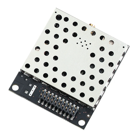
Laird AC4490 Quick setup guide

AC4490 Hardware Integration Guide
Embedded Wireless Solutions Support Center:
http://ews-support.lairdtech.com
www.lairdtech.com/ramp
2
© Copyright 2016 Laird. All Rights Reserved
Americas: +1-800-492-2320
Europe: +44-1628-858-940
Hong Kong: +852 2923 0610
REVISION HISTORY
Versio
n
Date
Description
Approved By
4.2
16 Dec
2013
Separated into two separate docs (Hardware Integration Guide
and User Guide). Information in this document was originally part
of the User Guide.
Added a Related Documents section.
Note: Starting at Rev 4.2 to match the current User Guide.
Sue White
4.3
09 Apr
2014
Updated Serial Interface information to:
Serial Interface and
Digital I/O
3.3V TTL only, all part numbers
UART baud rates from
1200 bps to 115,200 bps
Chris Downey
4.4
28 Apr
2014
Updated Serial Interface information to:
Serial Interface and I/O
3.3V TTL
UART baud rates from
1200 bps to 115,200 bps
Chris Downey
4.5
4 Aug
2014
Added Approved Antenna List
Chris Downey
4.6
18 May
2017
Removed references to EOL part numbers
Jonathan Kaye
FCC Notice
WARNING: This device complies with Part 15 of the FCC Rules. Operation is subject to the following
two conditions: (1) This device may not cause harmful interference and (2) This device must accept
any interference received, including interference that may cause undesired operation.
RF Exposure/Installation Instructions
WARNING: To satisfy FCC RF exposure requirements for mobile transmitting devices, this equipment
must be professionally installed such that the end user is prevented from replacing the antenna with
a non-approved antenna. The end user should also be prevented from being within 20cm of the
antenna during normal use with the exception of hands, feet, wrists and ankles.
The preceding statement must be included as a CAUTION statement in manuals for OEM products to
alert users on FCC RF Exposure compliance.
Caution: Any change or modification not expressly approved by Laird could void the user’s authority to
operate the equipment.

AC4490 Hardware Integration Guide
Embedded Wireless Solutions Support Center:
http://ews-support.lairdtech.com
www.lairdtech.com/ramp
3
© Copyright 2016 Laird. All Rights Reserved
Americas: +1-800-492-2320
Europe: +44-1628-858-940
Hong Kong: +852 2923 0610
CONTENTS
AC4490 RF Transceiver................................................................................................................................. 5
Overview.................................................................................................................................................... 5
Features ........................................................................................................................................................ 5
Networking and Security ........................................................................................................................... 5
Easy to Use ................................................................................................................................................ 5
Detailed Specifications ................................................................................................................................ 5
Electrical Specifications ............................................................................................................................... 7
Hardware.................................................................................................................................................... 10
Pin Definitions .......................................................................................................................................... 10
Pin Descriptions........................................................................................................................................ 12
Generic I/O .............................................................................................................................................. 12
TXD & RXD .............................................................................................................................................. 12
CTS ....................................................................................................................................................... 12
GND ........................................................................................................................................................ 12
RTS.......................................................................................................................................................... 12
Test ...................................................................................................................................................... 12
RSSI ......................................................................................................................................................... 13
UP_Reset ................................................................................................................................................. 13
CMD /Data ............................................................................................................................................ 14
AD In....................................................................................................................................................... 14
In Range ............................................................................................................................................... 14
Serial Interface ........................................................................................................................................... 14
Serial Communications............................................................................................................................. 14
Asynchronous Operation .......................................................................................................................... 14
Parity........................................................................................................................................................ 14
Serial Interface Baud Rate......................................................................................................................... 15
OEM Host Data Rate................................................................................................................................ 16
Radio Interface........................................................................................................................................... 16
Protocol Status / Receive Acknowledgement ............................................................................................ 16
Protocol Status ........................................................................................................................................ 16
Receive Acknowledgement ...................................................................................................................... 16
Flow Control ............................................................................................................................................ 16
CTS On/CTS On Hysteresis (Flow Control) ................................................................................................ 16
Security ....................................................................................................................................................... 18
Spread Spectrum History ......................................................................................................................... 18
How Spread Spectrum Works .................................................................................................................. 18
Frequency Hopping Spread Spectrum ...................................................................................................... 18
AC4490 Security Features........................................................................................................................ 19
AC4490 Mechanical and Layout ............................................................................................................... 20
Mechanical Drawings ............................................................................................................................... 20
AC4490 Timing Diagrams .......................................................................................................................... 23
Ordering Information................................................................................................................................ 24
Product Part Number Tree ........................................................................................................................ 24
Developer Kit Part Number....................................................................................................................... 24
Compliance Information ........................................................................................................................... 24
AC4490- 1x1 ........................................................................................................................................... 24

AC4490 Hardware Integration Guide
Embedded Wireless Solutions Support Center:
http://ews-support.lairdtech.com
www.lairdtech.com/ramp
4
© Copyright 2016 Laird. All Rights Reserved
Americas: +1-800-492-2320
Europe: +44-1628-858-940
Hong Kong: +852 2923 0610
Agency Identification Numbers................................................................................................................. 24
Approved Antenna List............................................................................................................................. 25
FCC / IC Requirements for Modular Approval ........................................................................................... 25
OEM Equipment Labeling Requirements................................................................................................... 26
Antenna Requirements............................................................................................................................. 26
Warnings Required in OEM Manuals ........................................................................................................ 26
Channel Warning ..................................................................................................................................... 26
Appendix I: 5V to 3.3V Levels ................................................................................................................... 27
Voltage Level Conversion IC’s................................................................................................................... 27
Passive Resistor Voltage Divider ................................................................................................................ 27
Appendix II: Sample Power Supply........................................................................................................... 28
Bill of Materials ........................................................................................................................................ 28
Schematic ................................................................................................................................................ 28
Switching Power Supply .......................................................................................................................... 28
PCB Layout............................................................................................................................................... 29
Appendix III: Product Throughput............................................................................................................ 30
Related Documents and Files .................................................................................................................... 31

AC4490 Hardware Integration Guide
Embedded Wireless Solutions Support Center:
http://ews-support.lairdtech.com
www.lairdtech.com/ramp
5
© Copyright 2016 Laird. All Rights Reserved
Americas: +1-800-492-2320
Europe: +44-1628-858-940
Hong Kong: +852 2923 0610
AC4490 RF TRANSCEIVER
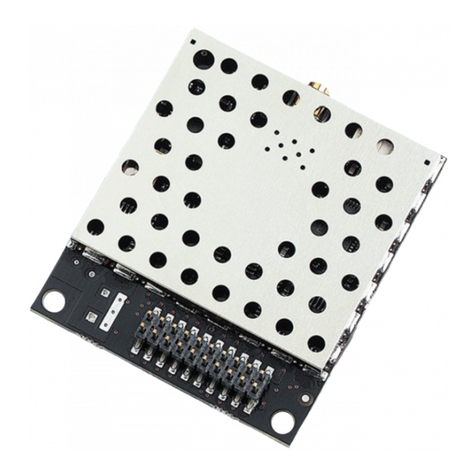
The compact AC4490 900 MHz transceiver can replace miles of cable in harsh industrial environments. Using
field-proven frequency hopping spread spectrum (FHSS) technology which needs no additional FCC licensing
in the Americas, OEMs can easily make existing systems wireless with little or no RF expertise.
Overview
The AC4490 is a cost effective, high performance, frequency hopping spread spectrum transceiver designed
for integration into OEM systems operating under FCC part 15.247 regulations for the 900 MHz ISM band.
AC4490 transceivers provide an asynchronous TTL level serial interface for OEM Host communications, which
include both system and configuration data. The Host supplies system data for transmission to other Host(s).
Configuration data is stored in the on-board EEPROM. All frequency hopping, synchronization, and RF system
data transmission/reception is performed by the transceiver.
To boost data integrity and security, the AC4490 uses Laird’s field-proven FHSS technology featuring optional
Data-Encryption Standards (DES). Fully transparent, these transceivers operate seamlessly in serial cable
replacement applications.
AC4490 transceivers can operate in Point-to-Point, Point-to-Multipoint, Client-Server, or Peer-to-Peer
architecture. One transceiver is configured as a server with one or many client-configured transceivers
synchronized to it. To establish synchronization between transceivers, the server emits a beacon; upon
detecting a beacon an RF link is established and a GPIO is toggled to signify to the host that the link is active.
This document contains information about the hardware and software interface between a Laird AC4490
transceiver and an OEM Host. Information includes the theory of operation, specifications, interface
definition, configuration information and mechanical drawings. The OEM is responsible for ensuring the final
product meets all appropriate regulatory agency requirements listed herein before selling any product.
Note: Unless mentioned by name, the AC4490 module is referred to as the “radio” or “transceiver”.
Individual naming is used to differentiate product specific features. The host (PC / Microcontroller /
Any device to which the AC4490 module is connected) will be referred to as “OEM Host”.
FEATURES
Networking and Security
Generic I/O digital lines and integrated DAC/ADC functions
Retries and Acknowledgements
API Commands to control packet routing and
acknowledgement on a packet-by-packet basis
Frequency Hopping Spread Spectrum for security and
interference rejection
Customizable RF Channel number and system ID
Dynamic link analysis, remote radio discovery
Low latency and high throughput
Hardware Protocol Status monitoring
Easy to Use
Continuous 76.8 Kbps RF data stream
Software selectable interface baud
rates from 1200 bps to 115.2 Kbps
Low cost, low power and small size
ideal for high volume, portable and
battery powered applications
All modules are qualified for Industrial
temperatures (-40° C to 85° C)
Advanced configuration available using
AT commands
DETAILED SPECIFICATIONS
Table 1: AC4490 Specification table
GENERAL

AC4490 Hardware Integration Guide
Embedded Wireless Solutions Support Center:
http://ews-support.lairdtech.com
www.lairdtech.com/ramp
6
© Copyright 2016 Laird. All Rights Reserved
Americas: +1-800-492-2320
Europe: +44-1628-858-940
Hong Kong: +852 2923 0610
20 Pin Interface Connector
Molex 87759-0030, mates with Samtec SMM-110-02-S-D
RF Connector
MMCX jack Johnson Components 135-3711-822
Antenna
AC4490-1x1: Customer must provide
AC4490-200: External antenna with MMCX plug or integral antenna
AC4490-1000: External antenna with MMCX plug
Serial Interface and I/O
3.3V TTL
UART baud rates from 1200 bps to 115,200 bps
Power Consumption
(typical)
Duty Cycle (Tx = Transmit, Rx = Receive)
10%Tx
50%Tx
100%
100%Rx
Pwr-
down
Deep
Sleep
1x1
33 mA
54 mA
80 mA
28 mA
15 mA
3 mA
200
38 mA
68 mA
106 mA
30 mA
19 mA
6 mA
1000
130 mA
650 mA
1300 mA
30 mA
19 mA
6 mA
Channels
3 Channel Sets comprising 56 total channels.
AC4490-1x1: 3 Channel Sets
AC4490-200: 3 Channel Sets
AC4490-1000: 2 Channel Sets
Security
One byte System ID. 56-bit DES encryption key
Interface Buffer Size
Input/Output: 256 bytes each
TRANCEIVER
Frequency Band
902 –928 MHz
RF Data Rate
76.8 Kbps fixed
RF Technology
Frequency Hopping Spread Spectrum (FHSS)
Output Power
Conducted (no antenna)
EIRP (3 dBi gain antenna)
1x1
10 mW typical
20 mW typical
200
100 mW typical
200 mW typical
1000
743 mW typical
1486 mW typical
Supply Voltage
1x1
VCC: 3.3 V, ±50 mV ripple
VPA: 3.3 V, ±50 mV ripple
200
VCC: 3.3 –5.5 V, ±50 mV ripple
VPA: 3.3 –5.5 V, ±50 mV ripple
1000*
VCC: 3.3 –5.5 V ±50 mV ripple
VPA: 3.3 ±3%, ±100 mV ripple
*VCC & VPA may be tied together, provided the supply voltage never falls
below 3.3 V and is capable of supplying 1.5 A of current. VCC & VPA are
internally connected on the AC4490-200 only.
Sensitivity
RF Data Rate
Typical
76.8 Kbps
-100 dBm
76.8 Kbps (AC4490LR-1000)
-110 dBm
Note: Receive sensitivity listed for US and Australian modes. Radios ordered
per Brazilian regulations have a receive sensitivity of -80 dBm.
EEPROM write cycles
20000
Hop period
20 ms

AC4490 Hardware Integration Guide
Embedded Wireless Solutions Support Center:
http://ews-support.lairdtech.com
www.lairdtech.com/ramp
7
© Copyright 2016 Laird. All Rights Reserved
Americas: +1-800-492-2320
Europe: +44-1628-858-940
Hong Kong: +852 2923 0610
TRANCEIVER
Range, Outdoor Line of
Site
(based on 3dBi gain
antenna)
1x1
Up to 1 mile
200
Up to 4 miles
1000
Up to 20 miles
LR1000
Up to 40 miles
Note: Distance based on US and Australian Modes
ENVIRONMENTAL
Temperature (Operational)
-40° C to +80° C (-40° F to +176° F)
Temperature (Storage)
-50° C to +85° C (-58°F to +185° F)
Humidity (non-condensing)
10% - 90%
PHYSICAL
Dimensions
Transceiver w/ MMCX connector: 1.65” x 1.9” x 0.20”
Transceiver w/ integral antenna: 1.65” x 2.65” x 0.20”
AC4490-1x1: 1.00” x 1.00” x 0.162”
CERTIFICATIONS
AC4490-200
AC4490-1000
FCC Part 15.247
KQL-4x90200
KQLAC4490
Industry Canada (IC)
2268C-4x90200
2268C-AC44901000
Caution! ESD Sensitive Component. You must use proper ESD precautions when
handling this device to prevent permanent damage.
External ESD protection is required to protect this device from damage as required
to pass IEC 61000-4-2 or ISO 10605 based on end system application.
ELECTRICAL SPECIFICATIONS
Table 2: Input Voltage Characteristics
AC44901x1 / AC4490-1000M
AC4490-200X
Signal Name
High
Min.
High
Max.
Low
Min.
Low
Max.
High
Min.
High
Max.
Low
Min.
Low
Max.
Unit
RXD
2.31
3.3
0
0.99
2
5.5
0
0.8
V
GI0
2.31
3.3
0
0.99
2
5.5
0
0.8
V
RTS
2.31
3.3
0
0.99
2
5.5
0
0.8
V
Test
2.31
3.3
0
0.99
2
5.5
0
0.8
V
GI1
2.31
3.3
0
0.99
2
5.5
0
0.8
V
UP_RESET
0.8
3.3
0
0.6
0.8
5
0
0.6
V
CMD /Data
2.31
3.3
0
0.99
2
5.5
0
0.8
V
AD In
N/A
3.3
0
N/A
N/A
3.3
0
N/A
V

AC4490 Hardware Integration Guide
Embedded Wireless Solutions Support Center:
http://ews-support.lairdtech.com
www.lairdtech.com/ramp
8
© Copyright 2016 Laird. All Rights Reserved
Americas: +1-800-492-2320
Europe: +44-1628-858-940
Hong Kong: +852 2923 0610
Table 3: Output Voltage Characteristics
Signal Name
Module Pin
1x1 Pin
Type
High Min.
Low Max.
Unit
GO0
1
19
O
2.5 @ 8 mA
0.4 @ 8 mA
V
TXD
2
6
O
2.5 @ 2 mA
0.4 @ 2 mA
V
Hop Frame
6
1
O
2.5 @ 2 mA
0.4 @ 2 mA
V
CTS
7
9
O
2.5 @ 2 mA
0.4 @ 2 mA
V
GO1
9
19
O
2.5 @ 2 mA
0.4 @ 2 mA
V
RSSI
13
12
O
See Figure 1
See Figure 1
V
DA_Out
19
20
O
N/A
N/A
V1
In Range
20
18
O
2.5 @ 2 mA
0.4 @ 2 mA
V
1. DA_Out is an unbuffered, high impedance output and must be buffered by the OEM Host when used.

AC4490 Hardware Integration Guide
Embedded Wireless Solutions Support Center:
http://ews-support.lairdtech.com
www.lairdtech.com/ramp
10
© Copyright 2016 Laird. All Rights Reserved
Americas: +1-800-492-2320
Europe: +44-1628-858-940
Hong Kong: +852 2923 0610
HARDWARE
Pin Definitions
The AC4490 has a simple interface that allows OEM host communications with the transceiver and shows the
connector pin numbers and associated functions.
Table 4: AC4490 Pin Definitions
Module
Pin
1x1
Pin
Type
Signal Name
Function
1
4
O
GO0
Generic Output pin
2
6
O
TXD
Serial data output from the module to the OEM Host.
3
7
I
RXD
Serial data input to the module from the OEM Host.
4
51
GI0
Generic Input pin
5
3
GND
GND
Signal Ground
6
O
Hop Frame
Pulses low when the transceiver is hopping frequencies.
7
9
O
CTS
Clear to Send –Active Low when the transceiver is ready to accept
data for transmission. CTS should be monitored by the OEM Host
& data flow to the radio should cease when CTS is High.
8
101
I
RTS
Request to Send –When enabled in EEPROM, the OEM Host can
take this High when it is not ready to accept data from the
transceiver.
Note:Keeping RTS High for too long can cause data loss.
9
19
O
GO1
Generic Output pin
10
2
PWR
VCC
Powers the radio and microcontroller. Must be connected.
1x1:
3.3 V, +/- 50 mV ripple
200:
3.3 –5.5 V, +/- 50 mV ripple (Pin 10 is internally
connected to Pin 11)
1000:
3.3 –5.5V, +/-50mV ripple
11
11
PWR
VPA
Powers the power-amplifier and draws most current when in TX
mode. Must be connected.
1x1:
3.3 V, +/- 50 mV ripple
200:
3.3 –5.5 V, +/- 50 mV ripple (Pin 11 is internally
connected to Pin 10)
1000:
3.3 V +/- 3%, +/- 100 mV ripple
12
23
I
Test
Test Mode –When pulled logic Low and then applying power or
resetting, the transceiver’s serial interface is forced to a 9600, 8-N-
1 rate. To exit, the transceiver must be reset or power-cycled with
Test Mode logic High.
13
12
O
RSSI
Received Signal Strength - An analog output giving an
instantaneous indication of received signal strength. Only valid
while in Receive Mode.
14
211
I
GI1
Generic Input pin
15
16
I
UP_RESET
RESET –Controlled by the AC4490 for power-on reset if left
unconnected. After a stable power-on reset, a logic High pulse will
reset the transceiver.
16
13
GND
GND
Signal Ground

AC4490 Hardware Integration Guide
Embedded Wireless Solutions Support Center:
http://ews-support.lairdtech.com
www.lairdtech.com/ramp
11
© Copyright 2016 Laird. All Rights Reserved
Americas: +1-800-492-2320
Europe: +44-1628-858-940
Hong Kong: +852 2923 0610
Module
Pin
1x1
Pin
Type
Signal Name
Function
17
17
I
CMD /Data
When logic Low, the transceiver interprets OEM Host data as
command data. When logic High, the transceiver interprets OEM
Host data as transmit data.
18
152
I
AD In
10-bit Analog Data Input
19
203
O
DA_Out
10-bit Analog Data Output
20
18
O
In_Range
When logic Low, a client is in range of a server on same Channel
and System ID. Always low on a server radio.
N/A
14
RF
RF Port
RF Interface
N/A
22
I
Reset
Active Low version of UP_RESET. If RESET is used, UP_RESET
should be left floating and if UP_RESET is used, RESET should be
left floating.
1. Must be tied to VCC or GND if not used. Should never be permitted to float.
2. If used, requires a shunt 0.1 μF capacitor at pin 15 followed by a series 1 k resistor.
3. If used, requires a series 1 k resistor at pin 20 followed by a shunt 0.1 μF capacitor.
Notes: All I/O is 3.3 V TTL with exception of 5 V inputs on AC4490-200.
All inputs are weakly pulled High (10 k) and may be left floating during normal operation.
Minimum connections: VCC, VPA, GND, TXD, & RXD.
Signal direction depends on the transceiver.
Leave unused pins disconnected.

AC4490 Hardware Integration Guide
Embedded Wireless Solutions Support Center:
http://ews-support.lairdtech.com
www.lairdtech.com/ramp
12
© Copyright 2016 Laird. All Rights Reserved
Americas: +1-800-492-2320
Europe: +44-1628-858-940
Hong Kong: +852 2923 0610
Pin Descriptions
Generic I/O
Both GI0/1 pins serve as generic input pins and both GO0/1 pins server as generic output pins. Reading and
writing of these pins can be performed using CC Commands. These pins alternatively serve as control pins
when modem mode is enabled.
TXD & RXD
Serial TTL
The AC4490-200 accepts 3.3 or 5 V DC TTL level asynchronous serial data on the RXD pin and
interprets that data as either command data or transmit data. Data is sent from the transceiver,
at 3.3V levels, to the OEM host via the TXD pin.
Note: The AC4490-1000 and AC4490-1x1 transceivers only accept 3.3 V level signals.
CTS
The AC4490 has an interface buffer size of 256 bytes. If the buffer fills up and more bytes are sent to the
transceiver before the buffer can be emptied, data loss occurs. The transceiver prevents this loss by asserting
CTS High as the buffer fills up and asserting CTS Low as the buffer is emptied. CTS On and CTS On Hysteresis
control the operation of CTS. CTS On specifies the amount of bytes that must be in the buffer for CTS to be
disabled (logic High). Even while CTS is disabled, the OEM host can send data to the transceiver, but it should
do so carefully.
Note: The CTS On and CTS On Hysteresis bytes of the EEPROM can be set to 1, in which case CTS goes
high as data is sent in and low when the buffer is empty.
GND
Signal Ground. Pins are internally connected.
RTS
With RTS disabled, the transceiver sends any received data to the OEM host when it is received. However,
some OEM hosts are not able to accept data from the transceiver all of the time. With RTS enabled, the OEM
host can prevent the transceiver from sending data by setting RTS logic High. Once RTS is set logic Low, the
transceiver can send packets to the OEM host as they are received.
Note: Leaving RTS logic high for too long can cause data loss once the 256 byte receive buffer fills up.
Test
When pulled logic Low before applying power or resetting, the transceiver’s serial interface is forced to 9600
baud, 8-N-1 (8 data bits, No parity, 1 stop bit). To exit, the transceiver must be reset or power-cycled with
Test pin logic High. This pin is used to recover transceivers from unknown baud rates only. It should not be
used in normal operation. Instead, the transceiver Interface Baud Rate should be programmed to 9600 baud
if that rate is desired for normal operation.

AC4490 Hardware Integration Guide
Embedded Wireless Solutions Support Center:
http://ews-support.lairdtech.com
www.lairdtech.com/ramp
13
© Copyright 2016 Laird. All Rights Reserved
Americas: +1-800-492-2320
Europe: +44-1628-858-940
Hong Kong: +852 2923 0610
Note: Laird does not recommend permanently grounding the Forced_9600 pin. This mode was intended
for recovering transceivers from unknown settings and was not intended to be used in real-time
communications. The following modes are affected:
Modem mode = disabled
Parity mode = disabled
Interface Timeout = 0x40
It is also possible that future modes will be disabled by grounding Forced_9600.
RSSI
Instantaneous
RSSI
Received Signal Strength Indicator can be used by the OEM Host as an indication of
instantaneous signal strength at the receiver. The OEM Host must calibrate RSSI without an
RF signal present at the receiver.
Calibration is accomplished by following these steps:
1. Power up only one transceiver in the coverage area.
2. Measure the RSSI to obtain the minimum value with no other signal present.
3. Power up another transceiver and begin sending data from that transceiver to the
transceiver being measured. Make sure the two transceivers are separated by
approximately ten feet.
4. Measure the peak RSSI, while the transceiver is actively receiving data from the
remote transceiver, to obtain a maximum value at full signal strength.
The following equation approximates the RSSI curve:
Signal Strength (dBm) = (-46.9 × VRSSI ) –53.9
Figure 2: RSSI Voltage vs. Received Signal Strength
Validated RSSI
Because RSSI is only valid when the local transceiver is receiving an RF packet from a remote
transceiver, instantaneous RSSI is tricky to use. Therefore, the transceiver stores the most
recent valid RSSI value. The OEM host issues the Report Last Good RSSI command to request
that value. Additionally, validated RSSI can be obtained from Receive Packet and Send Data
Complete API commands and from the Probe command. Validated RSSI is not available at
the RSSI pin.
UP_Reset
UP_Reset provides a direct connection to the reset pin on the AC4490 microprocessor and is used to force a
soft reset.

AC4490 Hardware Integration Guide
Embedded Wireless Solutions Support Center:
http://ews-support.lairdtech.com
www.lairdtech.com/ramp
14
© Copyright 2016 Laird. All Rights Reserved
Americas: +1-800-492-2320
Europe: +44-1628-858-940
Hong Kong: +852 2923 0610
CMD /Data
When CMD is held High the transceiver interprets incoming OEM Host data as transmit data to be sent to
other transceivers. When CMD Data is held Low the transceiver interprets OEM Host data as command
data.
AD In
AD In can be used as a cost savings to replace Analog-to-Digital converter hardware. Reading of this pin can
be performed locally using the Read ADC command. See the AC4490 User Guide for command descriptions.
In Range
Asserts logic Low when a client transceiver is in range of a server radio operating on the same RF Channel
and System ID. If a client cannot hear a server for the amount of time defined by Range Refresh, it will drive
In_Range igh and enter search mode looking for a server. When a server is detected, In_Range will
always rep In_Range will always report Low on server transceivers.
SERIAL INTERFACE
For the OEM host and a transceiver to communicate via serial interface they must share a serial data rate.
Refer to the following sections to ensure that the OEM host data rate matches the serial interface baud rate.
Serial Communications
The AC4490 is a TTL device which may connect to a compatible UART (Universal Asynchronous Receiver
Transmitter) or level translator to connect to serial devices. The UART mainly transmits or receives serial data.
Asynchronous Operation
Since there is no separate clock in asynchronous operation, the receiver must use a fixed baud rate and
START and STOP bits to synchronize with the transmitter. Figure 3 shows a typical asynchronous mode signal.
Figure 3: Asynchronous Mode Signal
The UART outputs and inputs logic level signals on the TX and RX pins. The signal is high when no data is
being transmitted and low when transmission begins. The signal stays low for the duration of the START bit
and is followed by the data bits (LSB first). The STOP bit follows the last data bit and is always high. When the
STOP bit finishes, the START bit of the next transmission can occur.
Parity
A parity bit is used to provide error checking for a single bit error. When a single bit is used, parity can be
either even or odd. Even parity means that the number of ones in the data plus the parity equals an even
number and vice-versa. The ninth data bit can be used as a parity bit if the data format requires eight data
bits and a parity bit as shown in Figure 4.

AC4490 Hardware Integration Guide
Embedded Wireless Solutions Support Center:
http://ews-support.lairdtech.com
www.lairdtech.com/ramp
15
© Copyright 2016 Laird. All Rights Reserved
Americas: +1-800-492-2320
Europe: +44-1628-858-940
Hong Kong: +852 2923 0610
Figure 4: Even Parity Bit
Note: Enabling parity cuts throughput and the interference buffer in half.
Table 5 displays supported asynchronous serial data formats:
Table 5: Supported Serial Formats
Data Bits
Parity
Stop Bits
Transceiver Programming Requirements
8
N
1
Parity Disabled
7
N
2
Parity Disabled
7
E, O, M, S
1
Parity Disabled
9
N
1
Parity Enabled
8
N
2
Parity Enabled
8
E, O, M, S
1
Parity Enabled
7
E, O, M, S
2
Parity Enabled
Mark (M) corresponds to 1 & Space (S) corresponds to 0
Serial Interface Baud Rate
This two-byte value determines the baud rate used for communicating over the serial interface between the
OEM Host and the transceiver. This rate is independent of the RF baud rate, which is fixed at 76.8 Kbps.
Table 6 lists values for some common baud rates.
Note: Baud rates below 1200 baud are not supported.
For a baud rate to be valid, the calculated baud rate must be within ±3% of the OEM host baud rate. If the
Test pin (pin 12) is pulled Logic Low at reset, the baud rate will be forced to 9600. For baud rate values other
than those shown in Table 6, the following equations can be used:
Table 6: Baud Rate / Interface Timeout
Baud Rate
BaudL (0x42)
BaudH (0x43)
Minimum Interface
Timeout (0x58)
Stop Bit Delay
(0x3F)
115200
0xFE
0x00
0x02
0xFF
576001
0xFC
0x00
0x02
0x03
38400
0xFA
0x00
0x02
0x08

AC4490 Hardware Integration Guide
Embedded Wireless Solutions Support Center:
http://ews-support.lairdtech.com
www.lairdtech.com/ramp
16
© Copyright 2016 Laird. All Rights Reserved
Americas: +1-800-492-2320
Europe: +44-1628-858-940
Hong Kong: +852 2923 0610
Baud Rate
BaudL (0x42)
BaudH (0x43)
Minimum Interface
Timeout (0x58)
Stop Bit Delay
(0x3F)
28800
0xF8
0x00
0x02
0x0E
19200
0xF4
0x00
0x03
0x19
14400
0xF0
0x00
0x04
0x23
9600
0xE8
0x00
0x05
0x39
4800
0xD0
0x00
0x09
0x7A
2400
0xA0
0x00
0x11
0xFC
1200
0x40
0x00
0x21
0x002
1. 57600 is the default baud rate
2. 0x00 yields a stop bit of 421 µSec. The stop bit at 1200 baud should be 833 µSec.
OEM Host Data Rate
The OEM host data rate is the rate with which the OEM host and transceiver communicate over the serial
interface. This rate is independent of the RF baud rate, which is fixed at 76.8 Kbps. Possible values range
from 1200 bps to 115200 bps.
RADIO INTERFACE
Protocol Status / Receive Acknowledgement
Note: Implemented in firmware v6.3 and later.
When enabled in EEPROM, GO0 and GO1 perform the functions of Protocol Status and Receive
Acknowledgement.
Protocol Status
Every time the radio hops to hop bin 0, the radio asserts GO0 Low for the entire hop bin. GO0 goes low at
the falling edge of the hop frame at the start of bin 0 and goes high with the rising edge of hop frame at the
end of bin 0. During all other hops, GO0 is high.
Note: This mode is incompatible with Modem mode.
Receive Acknowledgement
The radio uses GO1 to signal that a valid RF acknowledgement has been received from the remote radio.
GO1 is normally low and goes high within approximately 75 µSec of receiving a valid RF acknowledgement. It
remains high until the end (rising edge) of the next hop.
Note: This mode is incompatible with Modem mode.
Flow Control
CTS On/CTS On Hysteresis (Flow Control)
Flow control refers to the control of data flow between transceivers. It is the method used to handle data in
the transmit/receive buffer and determines how data flow between the transceivers is started and stopped.

AC4490 Hardware Integration Guide
Embedded Wireless Solutions Support Center:
http://ews-support.lairdtech.com
www.lairdtech.com/ramp
17
© Copyright 2016 Laird. All Rights Reserved
Americas: +1-800-492-2320
Europe: +44-1628-858-940
Hong Kong: +852 2923 0610
Often, one transceiver is capable of sending data at a higher rate than the other can receive it. Flow control
allows the slower device to tell the faster device when to pause and resume data transmission.
When a transceiver has data to send, it sends a Ready To Send signal and waits for a Clear To Send response
from the receiving unit. If the receiving radio is ready to accept data it will assert its CTS low. CTS will be
reasserted when the buffer contains the number of bytes specified by CTS_OFF (EEPROM address 0x5D).
These signals are sent apart from the data itself on separate wires.
Flow control refers to the control of data flow between transceivers. It is the method used to handle data in
the transmit/receive buffer and determines how data flow between the transceivers is started and stopped.
Often, one transceiver is capable of sending data faster than the other can receive it. Flow control allows the
slower device to tell the faster device when to pause and resume data transmission.
If RTS Enable is enabled, the receiver will monitor RTS. If the OEM asserts its CTS (transceivers RTS) high, the
transceiver will wait to send data over the serial bus to the OEM host until the RTS is asserted low. CTS
should be monitored by the OEM host since this is the manner the transceiver signals the OEM Host that it’s
transmit buffer may be full. If it asserts CTS high, the OEM host should stop sending data over the serial bus.
If CTS is asserted low, the OEM host can send data over the serial bus because the transmit buffer is not at its
limit.
Tip
Can I implement a design using just TXD, RXD, and GND (three-wire Interface)?
Yes. However, it is strongly recommended that your hardware monitor the CTS pin of the
radio. CTS is taken High by the radio when its interface buffer is getting full. Your hardware
should stop sending at this point to avoid a buffer overrun (and subsequent loss of data).
You can perform a successful design without monitoring CTS. However, you need to take into
account the amount of latency the radio adds to the system, any additional latency caused by
Transmit Retries or Broadcast Attempts, how often you send data, non-delivery network
timeouts and interface data rate. Polled type networks, where the server host requests data
from the client host and the client host responds, are good candidates for avoiding the use of
CTS. This is because no single transceiver can monopolize the RF link. Asynchronous type
networks, where any radio can send to another radio at any point in time, are much more
difficult to implement without the use of CTS.

AC4490 Hardware Integration Guide
Embedded Wireless Solutions Support Center:
http://ews-support.lairdtech.com
www.lairdtech.com/ramp
18
© Copyright 2016 Laird. All Rights Reserved
Americas: +1-800-492-2320
Europe: +44-1628-858-940
Hong Kong: +852 2923 0610
SECURITY
The AC4490 product family utilizes a Frequency Hopping Spread Spectrum (FHSS) technology which provides
the foundation for secure digital wireless communications. This section describes how spread spectrum
technology works and explains how an OEM can enable specific security features available in the AC4490.
Spread Spectrum History
Spread Spectrum dates back to World War II when a German scientist was granted a patent on a simple
frequency hopping continuous wave (CW) system. The allies also experimented with Spread Spectrum in
World War II. These early research and development efforts tried to provide countermeasures for radar,
navigation beacons, and communications. The U. S. military has used SS signals over satellites for at least 25
years.
How Spread Spectrum Works
SS radio communications has long been a favorite technology of the military because it resists jamming and is
difficult to intercept. This very same technology is now being widely used in the commercial, industrial, and
consumer markets.
The reason for this is because SS signals are distributed over a wide range of frequencies and then collected
onto their original frequency at the receiver, making them so inconspicuous as to be transparent. Just as they
are unlikely to be intercepted by a military opponent, they are also unlikely to interfere with other signals
intended for business and consumer users –even signals transmitted on the same frequencies.
Spread signals are intentionally made to be a much wider band than the information they are carrying and
they use special pseudo-noise codes to make them more noise-like. It is this characteristic that makes SS
signals difficult to detect, intercept, and demodulate. SS signals are hard to detect on narrowband equipment
because the signal's energy is spread over a much wider bandwidth. Further, SS signals are harder to jam
(interfere with) than narrowband signals and have a much lower probability to be intercepted, which is why
the military has used Spread Spectrum for so many years.
The spread of energy over a wide band makes SS signals less likely to interfere with narrowband
communications. Narrowband communications, conversely, cause little to no interference to SS systems
because the receiver effectively integrates the signal over a wide bandwidth to recover it.
Besides being hard to intercept and jam, spread spectrum signals are hard to exploit or imitate. Signal
exploitation is the ability of a non-network member to listen to and use information from the network
without being a valid network member or participant. Imitation is the act of falsely or maliciously introducing
false traffic or messages into a network.
SS signals are also more secure than narrowband radio communications. Thus SS signals can have any degree
of desired message privacy. Messages can also be encrypted to any level of desired secrecy. The very nature
of SS allows military or intelligence levels of privacy and security with minimal complexity. While these
characteristics may not be important to everyday business or consumer needs, they are important to
understand.
Frequency Hopping Spread Spectrum
A FHSS radio does what its name implies: it “hops” from frequency to frequency over a wide band. The
specific order in which frequencies are occupied is a function of a code sequence, and the rate of hopping
from one frequency to another is a function of the information rate.

AC4490 Hardware Integration Guide
Embedded Wireless Solutions Support Center:
http://ews-support.lairdtech.com
www.lairdtech.com/ramp
19
© Copyright 2016 Laird. All Rights Reserved
Americas: +1-800-492-2320
Europe: +44-1628-858-940
Hong Kong: +852 2923 0610
AC4490 Security Features
As mentioned at the beginning of this section, the AC4490 uses FHSS technology. In addition, Laird has
implemented three levels of security in the AC4490. All three levels of security are associated with their own
EEPROM parameter that can programmed for permanent operation or be changed during system operation
in volatile memory. The first two levels of security must be configured to establish a network of transceivers
and are defined as the Channel Number and System ID.
The Channel Number represents a specific hopping sequence and provides physical separation between
collocated networks. Thus, all transceivers in a network must be programmed to the same channel number.
There are a total of 48 channel numbers.
System ID is similar to a password character or network number and makes network eavesdropping more
difficult. A receiving radio does not go in range of or communicate with another radio on a different system
ID. There are a total of 256 system ID values.
If FHSS technology, channel number, and system ID are not enough to secure your data, the AC4490
supports the Data Encryption Standard (DES), which is the third level of security. Encryption is the process of
encoding an information bit stream to secure the data content. The algorithm described in this standard
specifies both encrypting and decrypting operations which are based on a binary number called a key.
A key of 56 bits is used to encrypt and decrypt the data. The encryption algorithm specified in this standard is
commonly known among those using the standard. The unique key chosen for use in a particular application
makes the results of encrypting data using the algorithm unique. Selection of a different key causes the
encrypted data that is produced for any given set of inputs to be different. The cryptographic security of the
data depends on the security provided for the key used to encrypt and decrypt the data.
Data can be recovered from the encrypted data only by using exactly the same key used to encrypt it.
Unauthorized recipients of the encrypted data who know the algorithm but do not have the correct key
cannot derive the original data algorithmically. However, anyone who does have the key and the algorithm
can easily decrypt the encrypted data and obtain the original data. A standard algorithm based on a secure
key thus provides a basis for exchanging encrypted data by issuing the key used to encrypt it to those
authorized to have the data.

AC4490 Hardware Integration Guide
Embedded Wireless Solutions Support Center:
http://ews-support.lairdtech.com
www.lairdtech.com/ramp
20
© Copyright 2016 Laird. All Rights Reserved
Americas: +1-800-492-2320
Europe: +44-1628-858-940
Hong Kong: +852 2923 0610
AC4490 MECHANICAL AND LAYOUT
Mechanical Drawings
Interface
Connector
20 pin OEM Interface connector (Molex 87759-0030, mates with Samtec SMM-110-02-S-D
MMCX Jack
20 pin OEM Interface connector (Molex 87759-0030, mates with Samtec SMM-110-02-S-D
Figure 5: AC4490 (with MMCX connector) Mechanical
Other manuals for AC4490
1
Table of contents
Other Laird Transceiver manuals

Laird
Laird CL4490 User manual

Laird
Laird AC4868 User manual

Laird
Laird CL4790 Quick setup guide

Laird
Laird CL4490 Quick setup guide

Laird
Laird CL024 User manual

Laird
Laird AC4490 User manual

Laird
Laird ConnexLink CL2510 User manual

Laird
Laird CL4790 User manual

Laird
Laird SDC-EC25N Quick setup guide

Laird
Laird AC4868-250 User manual