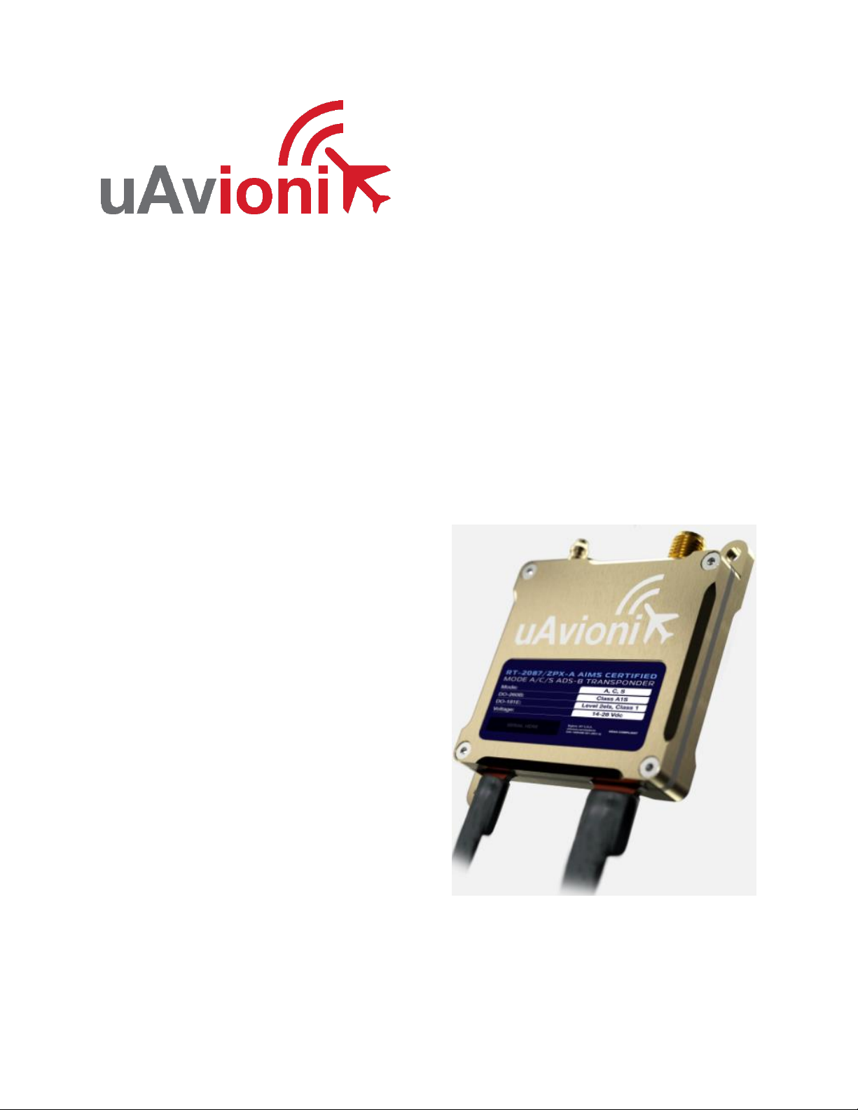
RT-2087/ZPX-A User and Installation Guide
UAV-1005667-001 Rev A ECCN 7A994 Page 5 | 48
3 Limited Warranty
uAvionix products are warranted to be free from defects in material and
workmanship for two years from the installation of ZPX-A in or on the
platform. For the duration of the warranty period, uAvionix, at its sole
discretion, will repair or replace any product which fails in normal use. Such
repairs or replacement will be made at no charge to the customer for parts
and labor, provided that the customer shall be responsible for any
transportation cost.
Restrictions: This warranty does not apply to cosmetic damage,
consumable parts, damage caused by accident, abuse, misuse, fire or
flood, theft, damage caused by unauthorized servicing, or product that has
been modified or altered.
Disclaimer of Warranty: IN NO EVENT, SHALL UAVIONIX BE LIABLE
FOR ANY INCIDENTAL, SPECIAL, INDIRECT OR CONSEQUENTIAL
DAMAGES, WHETHER RESULTING FROM THE USE, MISUSE OR
INABILITY TO USE THE PRODUCT OR FROM DEFECTS IN THE
PRODUCT. SOME STATES DO NOT ALLOW THE EXCLUSION OF
INCIDENTAL OR CONSEQUENTIAL DAMAGES, SO THE ABOVE
LIMITATIONS MAY NOT APPLY TO YOU.
Warranty Service: Warranty repair service shall be provided directly by
uAvionix. Proof of purchase for the product from uAvionix or authorized
reseller is required to obtain and better expedite warranty service.
Please contact uAvionix support with a description of the problem you are
experiencing. Also, please provide the model, serial number, shipping
address and a daytime contact number.
You will be promptly contacted with further troubleshooting steps or return
instructions. It is recommended to use a shipping method with tracking and
insurance.